1
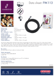
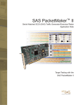
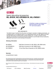
MIL-S800 User’s Guide
8 port 10/100BASE-TX Switch
Regulatory Approval
- FCC Class A
- UL 1950
- CSA C22.2 No. 950
- EN60950
- CE
- EN55022 Class B
- EN55024
Canadian EMI Notice
This Class A digital apparatus meets all the requirements of the Canadian Interference-Causing Equipment Regulations.
Cet appareil numerique de la classe A respecte toutes les exigences du Reglement sur le materiel brouilleur du Canada.
European Notice
Products with the CE Marking comply with both the EMC Directive (89/336/EEC) and the Low Voltage Directive (73/23/EEC) issued by the
Commission of the European Community Compliance with these directives imply conformity to the following European Norms:
-
EN55022 (CISPR 22) - Radio Frequency Interference
EN61000-X - Electromagnetic Immunity
EN60950 (IEC950) - Product Safety
Five-Year Limited Warranty
MiLAN Technology warrants to the original consumer or purchaser that each of it's products, and
all components thereof, will be free from defects in material and/or workmanship for a
period of five years from the original factory shipment date. Any warranty hereunder is
extended to the original consumer or purchaser and is not assignable.
MiLAN Technology makes no express or implied warranties including, but not limited to, any
implied warranty of merchantability or fitness for a particular purpose, except as expressly set
forth in this warranty. In no event shall MiLAN Technology be liable for incidental or
consequential damages, costs, or expenses arising out of or in connection with the
performance of the product delivered hereunder. MiLAN Technology will in no case cover damages
arising out of the product being used in a negligent fashion or manner.
Trademarks
The MiLAN logo and MiLAN Technology trademarks are registered trademarks ofof MiLAN Technology
in the United States and/or other countries.
To Contact MiLAN Technology
For prompt response when calling for service information, have the following information ready:
- Product serial number and revision
- Date of purchase
- Vendor or place of purchase
You can reach MiLAN Technology technical support at:
E-mail: [email protected]
Telephone: +1.408.744.2751
Fax: +1.408.744.2771
MiLAN Technology
1329 Moffett Park Drive
Sunnyvale, CA 94089
United States of America
Telephone: +1.408.744.2775
Fax: +1.408.744.2793
http://www.milan.com
info @ milan.com
© Copyright 2003 MiLAN Technology
P/N: 90000377_F
Table of Contents
Chapter 1. Introduction
1-1 General Description…………………………………….
1-2 Key Features………………………………………………
1-3 Package Contents………………………………………
1-4 Hardware Description…………………………………..
Pg 1
Pg. 1
Pg. 1
Pg. 2
Pg. 3
Chapter 2. Hardware Installation
2-1 Quick Installation………………………………………...
2-2 LED Descriptions………………………………………….
Pg 4
Pg. 4
Pg. 5
Chapter 3. Network Application
3-1 Stand Alone………………………………………………
3-2 Uplink Multiple Hubs…………………………………….
Pg 6
Pg. 6
Pg. 6
Chapter 4. Trouble Shooting
Pg 7
Chapter 5. Product Specifications
5-1 General Specification…………………………………..
5-2 Performance Specification
5-3 Physical & Environmental Specification……………..….
Pg 8
Pg. 8
Pg. 8
Pg. 8
Chapter 1 Introduction
1-1 General Description
The MIL-S800 switch provides eight auto-sensing 10/100Mbps RJ45 Ethernet ports. This high performance,
low cost, wire speed desktop switch is ideal for any network where 8 ports are needed, for a solution to an
enterprise need or for a home network. The MIL-S800 can be mounted on the wall with keyholes in the
chassis or magnetically attached to any metal surface.
1-2 Key Features
•
•
•
•
•
•
•
•
•
•
•
•
Compliant with IEEE 802.3, 802.3u & 802.3x standards
8 Auto-sensing RJ-45 ports for 10BASE-T or 100 BASE-TX connections
Embedded 2K entry MAC address table
512KB memory buffer sharing
Store-and-Forward operation support
Full duplex and half duplex flow control
Plug-and-Play configuration auto addresses learning
LED indicators for power, link speed 100Mbps, link and activity, full duplex and collision
Space-saving compact size
Wall or desktop mountable
Magnets provide installation on any metal surface
Auto MDI/MDIX
1
1-3 Package Contents
Your package contents should include the following parts:
•
•
•
•
•
•
One 8-port Auto-sensing switching Hub
One DC power adapter
This User’s Guide
Four rubber feet with adhesive pads
Two magnets
Warranty card
Figure 1. Package contents
2
1-4 Hardware Description
The Front Panel
The front panel contains power and LED Indicators.
Figure 2. Front panel view of the MIL-S800
Front panel LED Indicators
Per Device
Per Port
Power
100M (Link on 100Mbps)
LNK/ACT (Link/Activity)
FDX/COL (Full Duplex/Collision)
For LED details, please refer to Chapter 2, LED Descriptions.
The Rear Panel
The rear panel of the MIL-S800 consists of a DC power connector and 8 auto-sensing ports.
Figure 3. Rear panel view of the MIL-S800
· Eight Auto-sensing RJ-45 ports for 10BASE-T or 100 BASE-TX connections.
· Auto MDI/MDIX: Detects the straight cable connection, NIC or cascade to a hub or switch, without
changing the cable.
· DC Power Connector.
3
Chapter 2 Hardware Installation
2-1 Quick Installation
•
The MIL-S800 should be placed in a well-ventilated room with proper temperature and humidity.
•
Do not place the unit near water.
•
The maximum distance between the port to the standard network interface is 100 meters.
•
•
•
•
•
For desktop installation, ensure the surface is clean, smooth, level and sturdy. Apply self-adhesive rubber
feet to the bottom of the switch near the corners.
For wall installation, place two screws securely into the wall. Slide the cross recesses on the bottom of the
MIL-S800 onto the screws.
For mounting the MIL-S800 on a metal surface, install magnets as shown in instructions and apply to
surface.
Visually check that the power cord is not damaged. Plug the female end of the cord into the rear of the
MIL-S800 and the male end (power converter) into a power outlet.
Do not plug a phone jack connector into any RJ-45 port. This may cause damage. Use only twisted-pair
cables with RJ-45 connectors that conform to FCC standards.
Figure 4. Installation of switch
4
2-2 LED Descriptions
Figure 5. Front panel view of LED indicators
The following table lists the LEDs and their function.
5
Chapter 3 Network Application
3-1 Stand Alone
The application of a simple standalone switch is illustrated below. The maximum distance between the switch
and the workstation is 100 meters.
Figure 6. The switch as a backbone for a small 10/100BASE-TX network
3-2 Network
You can cascade the MIL-S800 to another hub or a switch without using a crossover cable.
Figure 7. Small Network Configuration
6
Chapter 4 Troubleshooting
•
Power
If the power indicator is not on after the power cord is plugged in, check the power outlet or power cord. If
you lose power after the switch has been operating for some time, check for loose power connections,
power losses or surges at the power outlet. Disconnect and reconnect the power. If the problem persists,
contact MiLAN Technical Support.
•
Cabling
Verify that the cabling type is correct. Be sure all cable connectors are securely seated in the required
ports. Use standard unshielded twisted-pair (UTP), Category 3, 4, or 5 cables. Use only Category 5
when there is a Fast Ethernet connection. Make sure the distance between the MIL-S800 and the
workstation, is less than 100 meters.
7
Chapter 5 Product Specification
5-1 General Specification
Standard Compliance
Number of Ports
Data Transfer Rate
Network Cables
LED Indicators
Per Device
Per Port
IEEE 802.3 10Base-T Ethernet
IEEE 802.3u 100Base-TX Fast Ethernet
8 10/100Mbps Auto-sensing RJ-45 ports
Ethernet :10Mbps(half duplex)
20Mbps(full duplex)
Fast Ethernet : 100Mbps(half duplex)
200Mbps(full duplex)
Unshielded twisted-pair cable
Power
LNK/ACT, 100M, FDX/COL
5-2 Performance Specification
Transmission Method
MAC address table
Maximum Forwarding
Rate(64byte packets)
Maximum Filtering
Rate(64byte packets)
Duplex mode
Store and forward
2 K entry MAC address table
14,880 pps /10 BASE-T
148,800 pps /100BASE-TX
14,880 pps /10BASE-T
148,800 pps/100BASE-TX
Supports both half and full duplex mode
5-3 Physical & Environmental Specification
Power Supply
Dimensions
Temperature
Humidity
EMI
External power adapter,
DC 9V, 700mA
4.2 Watt power consumption
6.5" (165mm) L x 4.0" (100mm) W x 1.0"
(25mm) H
Operating temperature:
0C to 45C (32F to113F)
Storage temperature:
-30C to 60C (-22F to 140F)
10% to 90% (non-condensing)
FCC Class B, CE mark
8
90000377_F
9