1
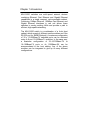
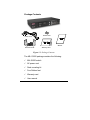
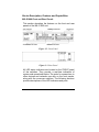
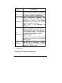
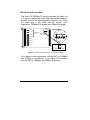
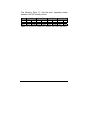
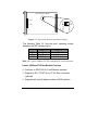
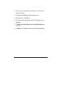
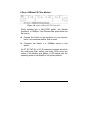
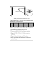
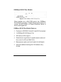
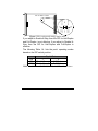
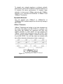
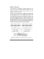
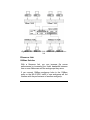
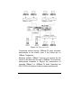
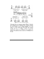
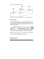
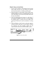
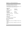
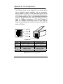
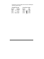
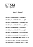
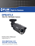
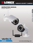
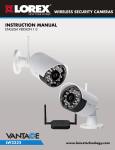
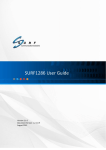
MIL-S1000 User’s Manual Copyright Statement COPYRIGHT 1999 ALL RIGHT RESERVED. First Edition. Printed in Taiwan. All trademarks are the properties of their respective owners. No portion of this document may be reproduced, altered, adapted or translated without the prior written approval. Warranty This information in this document is subject to change without notice. We make no warranty of any kind regarding this material, including, but not limited to, the implied warranties or merchantability and fitness for a particular purpose. Furthermore, we shall not be liable for errors contained herein or for incidental or consequential damage in connection with the furnishing, performance, or use of this material. FCC Statement This equipment has been tested and found to comply with the limits for a class A device, pursuant to part 15 of the FCC rules. These limits are designed to provide reasonable protection against harmful interference in a commercial installation. This equipment generates, uses and can radiate radio frequency energy and, if not installed and used in accordance with instructions, may cause harmful interference on radio communications. Operation of this equipment in a residential area is likely to cause harmful interference, in which case, the user will be requires to correct the interference at the user’s own expense. Table of Contents Chapter 1 Introduction Package Contents……….…………………………………….. 1-2 Device Description, Features and Capabilities …………… MIL-S1000 Front and Rear Panels……….……………… 1-3 1-3 8 ports 10/100Base-TX Module…….……………………… 1-5 8 ports 10/100Base-TX Module Features …..….… 1-5 2 ports 100Base-FX Fiber Module………………….…… 1-8 2 ports 100Base-FX Fiber Module Features ….….. 1-9 4 ports 100Base-FX Fiber Module ………..…………… 1-11 4 ports 100Base-FX Fiber Module Features ………. 1-12 1000Base-SX/LX Fiber Module …………………………..1-14 1000Base-SX/LX Fiber Module Features ……….…..1-14 Chapter 2 Planning your Network 10Base-T Ethernet Network Guidelines……………………. 2-1 100Base-T Ethernet Network Guidelines…………………… 2-2 1000Base-SX and LX Network Guidelines…………………. 2-3 Network Planning………………………………………………. 2-3 Expanded Networks………………………………….……….. 2-4 10Base-TX Networks…………………………………….. 2-4 100Base-TX Networks…………………………………… 2-5 Collapsed Backbone Line…………………………………….. 2-6 Fileserver Link………………………………………………….. 2-7 Multiport Bridge with High-Bandwidth Backbone……….. 2-9 Chapter 3 Installation Choosing A Location………………………………………….. 3-1 Rack Installation……………………………………………….. 3-2 Supplying Power………………………………………………. 3-3 Connecting the Switch..……………………………………... 3-4 Chapter 4 Module Install and Removed Handling the Modules…………………………………………. 4-1 Module Setup and installation……………………………… 4-2 Installing the Modules………………………………………… 4-3 Installing 10/100Base-TX Modules…… ………………. 4-3 Installing 100Base-FX Modules…… …………………… 4-3 Installing 1000Base-SX/LX Modules…… …………….. 4-4 Removing the Modules…………………………………………. 4-4 Appendix A Pin and Cable Specification…………..…. A-1 Appendix B Technical Specification……………….…… B-1 Chapter 1 Introduction MIL-S1000 switches are multi-speed network devices combining Ethernet, Fast Ethernet and Gigabit Ethernet capabilities in a single compact, rack-mountable cabinet. Combining 10Mbps Ethernet, 100Mbps Fast Ethernet and Gigabit Ethernet interfaces in one unit allows these switches to unclog existing LANs and provide a path to efficient, high-speed networking. The MIL-S1000 switch is a combination of a 4-slot host cabinet which accepts 4 different media modules and One RS-232 port for SNMP(Optional). A maximum configuration of 32 x 10/100Base-Tx switched ports can be achieved using 4×8 port 10/100Base-Tx modules. In the same way, a maximum configuration of 32×10/100Base-TX or 16×100Base-FX ports or 4x 1000Base-SX can be accommodated in the host cabling. Any of the above modules can be integrated to give up to many different configurations. Package Contents Rubber Feet Power Cord Manual Rack-Mount Kit Warranty Card Figure 1-1. Package Contents The MIL-S1000 package contains the following: ! MIL-S1000 switch ! AC power cord ! Rack mounting kit ! Four Rubber feet ! Warranty card ! User manual Device Description, Features and Capabilities MIL-S1000 Front and Rear Panels This section describes the features on the front and rear panels of the MIL-S1000 unit. Figure 1-2. Front Panel Figure 1-3. Rear Panel All LED status indicators are located on the FRONT panel of the switches. They provide a real-time indication of system and operational status. The ports for connections to other devices and networks are also on the front panels, along with the crossover switches. The following sections provide descriptions of the LED indicators and ports. LED Indicators Power Explanation The red power indicator is illuminated when power is provided to the switch and the switch is turned in the ON position. Green Link/Activity indicators are illuminated when the switch detects a connection to that port. The indicator Link/Activity blinks when data is transmitted over the network connected to that port. When a port is not connected, the indicator is off. Full Duplex/Col 100Mbps Red Full Duplex/Col indicators are illuminated when that port is in full duplex mode. The indicator is off when that port is in half duplex mode. When a collision occurs on the network connected to a port, that Full Duplex/Col indicator blinks. Green 100Mbps indicators are illuminated when the port is operating in 100Mbps mode. The indicator is off when the port is operating in 10Mbps mode. " Power Port The power port accepts the power plug. " Power Switch The power switch, located on the rear panel, controls the power supply. 8 ports 10/100Base-TX Module Figure 1-4. 8 port 10/100Base-TX Module When installed into a MIL-S1000 switch, the 10/100BaseTX Module provides 8 10/100Mbps Switch ports which can connect the MIL-S1000 to a 10Mbps or 100Mbps switch or end station. 8 Ports 10/100Base-Tx Module Features " 8 10/100Base-TX N-Way Switch ports. " Conforms to IEEE 802.3 10Base-T and IEEE 802.3u 100Base-TX and IEEE 802.3x standards " Store and forward switch architecture for abnormal packet filtering " Support for half and full duplex on all ports " Backplane up to 2.4Gbps " 2M memory Buffer support " Automatic address learning with 12K address entry storage " Filtering and forwarding packets per second rate of 14,880~148,800 DIP Switch with Link Mode The 8 port 10/100Base-TX module provides dip switch for 1 to 4 port to adjust link mode with other network devices. Another 4 ports use auto-negotiation protocol only. There are three type of link mode can be chosen, Autonegotiation, 100Mbps/Full duplex and 10Mbps/Full duplex. P ort 1 P ort 2 P ort 3 P ort 4 P ort 5 ON adjustable D IP S w itch for ports P ort 1 to P ort 4 P ort 1 P ort 3 1 2 3 4 5 6 7 8 P ort 2 P ort 6 P ort 4 O FF P ort 7 P ort 8 Full D uplex A utonegotiation 10M 1 2 100M Figure 1-5. Dip switch location and mode settings If you adjust to auto-negotiation, then the DIP for 100Mbps and 10Mbps is not effective. If you adjust to Full duplex, then the DIP for 100Mbps and 10Mbps is effective. The following Table 1-1. lists the ports’ operating modes based on the DIP switch position. SW ON OFF PORT 1 1 2 Full 10M Auto 100M PORT 2 3 4 Full 10M Auto 100M PORT3 5 6 Full 10M Auto 100M PORT4 7 8 Full 10M Auto 100M Table 1-1. 8 Ports 10/100Base-TX Module DIP switch functions 2 ports 100Base-FX Fiber Module Figure 1-6. 2 port 100Base-FX Module Front View When installed into a MIL-S1000 switch, this Module provides a 100Mbps Fast Ethernet fiber port which can be used to: # Connect the Switch to the backbone of your network; that is, to a basement switch, hub or router # Connect the Switch to a 100Mbps server or end-station An ST, SC, MT-RJ or VF-45 connector provides the link to the multi-mode fiber cabling and two indicators show the status of the Module at-a glance. A DIP-switch sets the operating mode to half duplex or full duplex (default). D IP S w itch Lo catio n ON H alf D up lex Full D uplex 2 P ort 2 1 O FF P ort 1 Figure 1-7. Dip switch location and mode settings The following Table 1-2. lists the ports’ operating modes based on the DIP switch position. SW ON OFF PORT 1 1 Half-Duplex Full-Duplex PORT 2 2 Half-Duplex Full-Duplex Table 1-2. 2 ports 100Base-FX Fiber ModuleDIP switch functions 2 ports 100Base-FX Fiber Module Features " Conforms to IEEE 802.3u Fast Ethernet standard " Support for SC, ST, MT-RJ or VF-45 fiber connectors (optional) " Supports half and full duplex modes via DIP switches " Store-and-forward switch architecture for abnormal packet filtering " 2 switching 100Mbps Fiber Ethernet ports " Backplane up to 2.4Gbps " Automatic address learning with 12K address entry storage " Filtering and forwarding rate of 148,800 packets per second " 100Base-FX uses 62.5/125 micron multi-mode fiber 4 Ports 100Base-FX Fiber Module Figure 1-8. 4 port 100Base-TX/FX Front View When installed into a MIL-S1000 switch, this Module provides 4 x 100Mbps Fast Ethernet fiber ports which can be used to: # Connect the Switch to the backbone of your network; that is, to a basement switch, hub or router. # Connector the Switch to a 100Mbps server or end station. An ST, SC, MT-RJ or VF-45 connector provides the link to the multi-mode fiber cabling and three LEDs show five status of the Module at-a glance. A DIP-switch sets the operating mode to half duplex or full duplex (default). P ort 1 P ort 2 ON H alf D uplex Full D uplex P ort 4 1 2 3 4 O FF D IP S w itch Locatio n P ort 3 Figure 1-9. Location and setting duplex mode The following Table1-3. lists the ports operating modes based on the DIP switch position. SW ON OFF PORT 1 1 Half-Duplex Full-Duplex PORT 2 2 Half-Duplex Full-Duplex PORT3 3 Half-Duplex Full-Duplex PORT4 4 Half-Duplex Full-Duplex Table 1-3. 4 ports 100Base-FX Fiber Module DIP switch functions 4 ports 100Base-FX Fiber Module Feature " Conforms to IEEE 802.3u Fast Ethernet standard " Support SC, ST, MT-RJ or VF-45 fiber connector (optional) " Support half and full duplex via DIP switches " Store-and-forward switch architecture for abnormal packets filtering " Backplane up to 2.4Gbps " Automatic address learning with 12K address entry storage " Filtering and forwarding rate 148,800 packets per second for 100Mbps " 100Base-FX uses 62.5/125 micron multi-mode fiber 1000Base-SX/LX Fiber Module Figure 1-10. 1000Base-SX/LX Front View When installed into a MIL-S1000 switch, the 1000BaseSX/LX Module provides 1 Gigabit Ethernet ports which can connect the MIL-S1000 to a Gigabit Backbone Switch or Server with Gigabit NIC. 1000Base-SX/LX Fiber Module Features " Conforms to IEEE 802.3z draft 4.2 and 802.3x standard " 1x1000Base-SX/LX Ethernet Port " 3M memory buffer support " Standard auto-negotiation for speed, duplex mode and flow-control for MII and GMII PHYs " Backpressure option and Limit4 option for half duplex " Automatic address learning with 12K address entry storage O FF Full D uplex D IP 2 D IP 1 Enable N -w ay D isable N -w ay 1 ON 2 H alf D uplex D IP S w itch Location Figure 1-11. Location and setting duplex mode If you adjust to Enable N-Way, then the DIP for Half-Duplex and Full-Duplex is not effective. If you adjust to Disable NWay, then the DIP for Half-Duplex and Full-Duplex is effective. The following Table 1-4. lists the ports’ operating modes based on the DIP switch position. Gigabit Port SW 1 2 ON Disable N-way Half Duplex OFF Enable N-way Full Duplex Table 1-4. 1000Base-SX/LX Fiber Module DIP switch functions Chapter 2 Planning your Network Before you install your MIL-S1000, you should review the guidelines for setting up Ethernet networks. Further, you should plan your network to take maximum advantage of its switching capabilities. 10Base-T Ethernet Network Guidelines # The maximum length of a 10Base-T cable segment is 100 meters (328 feet). # The maximum number of nodes on a 10Base-T segment is one (1) for regular 10Base-T. # The recommended cable type is EIA/TIA Category 3 or higher. # The maximum network diameter is 500 meters (1,640 feet) for Ethernet networks. # The maximum number of segments between any two nodes in the network is five. # The maximum number of hubs or repeaters between any two nodes in the network is four. 100Base-TX Ethernet Network Guidelines # The maximum length of a 100Base-TX cable segment is 100 meters (328 feet). # The maximum number of hubs on a 100Base-TX segment is one if using Class I hubs and two if using Class II hubs. # The recommended cable type is EIA/TIA Category 5 unshielded twisted-pair. # The maximum network diameter is 200 meters (656 feet) when using Class I hubs and 205 meters (672.5 feet) when using Class II hubs. 100BASE-FX Network Guidelines # In half duplex mode, the fiber optic segment cannot exceed 412m (1,135ft) in length. # In full duplex mode, the fiber optic segment cannot exceed 2km (6562 ft) in length. 1000BASE-SX and LX Network Guideline 1000BASE-SX # In multi-mode, the fiber optic segment cannot exceed 220m(62.5/125µm) or 500m(50/125µm) in length. 1000BASE-LX # In multi-mode, the fiber optic segment cannot exceed 550m(62.5/125µm), 550m(50/125µm) in length. # In single-mode the fiber optic segment cannot exceed 10km(9/125µm). Network Planning Using a switch, such as a MIL-S1000, can expand network topologies and enhance network performance. Each port on a switch connects to a separate network with its own collision domain. Separating networks with these switches allows you to expand 10Base-T networks past the four-hub limit and expand 100Base-TX networks past the one or two hub limit. These switches also filter incoming traffic. On standard hubs and repeaters, any data received on a port is forwarded to all of the other ports. On switches, data received on one port is forwarded only to the port of the destination device, and if the traffic is local, the data is not forwarded at all. Also, switches can forward multiple data transaction at once. To expand your network topology or enhance network performance, use the MIL-S1000 as collapsed backbone or to increase file server performance, to segment large networks, to interconnect 10Mbps networks with 100Mbps networks, or to overcome the limitations of 10Base-T and 100Base-TX networks. Expanded Networks You can expand your 10Base-T or 100Base-TX or 1000Base-SX/LX network beyond its hub limit by adding a MIL-S1000. 10Base-T Networks 10Base-T Networks are limited to four hubs between any two nodes. By adding your MIL-S1000 to a network, you can divide that network into segments with their own collision domains. In other words, you can connect one 10Base-T network with four hubs to your MIL-S1000. Then you can connect another 10Base-T network with four hubs to your MIL-S1000. You will then have one network with two collision domains, allowing four hubs on each port. Figure 2-1. Expanding your 10Base-T Network 100Base-TX Networks The hub limit of a 100Base-TX network depends on the class of the hub in the network. With a Class I hub, the network is limited to one hub. With a Class II hub, the network is limited to two hubs. However, you can expand your 100Base-TX network that includes either class of hub by adding a MIL-S1000. With the MIL-S1000 added to your 100Base-TX network, you can separate that network into individual segments with their own collision domains. In other words, you can connect one 100Base-T network with one or two hubs to the MIL-S1000, and you can connect another 100Base-TX network with one or two hubs to the MIL-S1000. You will then have one network with two collision domains. Figure 2-2. Expanding your 100Base-TX network (Class I) Collapsed Backbone Link Traditionally, bridges and routers have been used to link local area networks into one interconnected network. But these devices involve difficult management and long traffic delays. The MIL-S1000 providers multiport bridges with short delays, easy setup and maintenance, making it ideal for backbone links. Also, the Built-in filtering on this hub deceases network traffic, while the multiple ports that communicate simultaneously increases network performance. One or more of your hub's 100Mbps or 1000Mbps ports can be used as a high-speed backbone link to other hubs serving as collapsed backbones. Figure 2-3. MIL-S1000 100/1000 Hub in a collapsed backbone link Fileserver Link 100Base Solution With a fileserver link, you can increase file server performance by increasing the Hub's bandwidth between one or more fileservers and the workgroups they serve. If you connect 10Mbps workgroup hubs to the 10Mbps ports on the MIL-S1000, traffic in one workgroup will not interfere with the performance of another workgroup. Figure 2-4. Fileserver Link Connecting servers through 100Base-TX ports increases performance to the clients, even if the clients are on 10Base-T segments. Because multiple 10Base-T devices can access the file server at the same time through a 100Base-TX connection, performance increases to beyond the performance of standard 10Base-T or 100Base-TX hubs. Operating the MIL-S1000 at full duplex further increases performance 1000Base Solution You can upgrade your server with a Gigabit Ethernet NIC, and introduce a Gigabit backbone switch too. This contains several switch ports which provides much faster access to your server with minimum disruption. See Figure 16. Multiport Bridge with High-Bandwidth Backbone With a MIL-S1000, you can divide large network to ease congestion, and connect 10Base-T networks to 100BaseTX or 100Base to 1000Base networks for more flexibility. Adding your MIL-S1000 to a large network creates more segments in that network. The MIL-S1000 built-in filtering function separates a segment's local traffic from network traffic, reducing the amount of network traffic and easing congestion. Figure 2-5. Used as a Multiport Bridge Using your hub, you can also connect 10Base-T networks and 100Base-TX and 1000Base-SX/LX networks together for more flexibility in your network topology. As in the Figure 16 shown above, the MIL-S1000 can connect through one port to a 10Base-T network, and through another port, connect to a 100Base-TX port, creating one network. This switch can also connect to a 1000Base-LX or SX port. Chapter 3 Installation The MIL-S1000 can be installed quickly and easily. However, for an installation with minimum impact on the existing network, please read this chapter carefully. Installing a MIL-S1000 involves three steps: 1. Choosing a location 2. Supplying power 3. Connecting the switch Choosing A Location The location of the switch is based on the following criteria: " Avoid dusty locations. " Avoid electromagnetic noisy areas, such as locations close to power transformers or radio transmitters. " Avoid temperatures below 32 Degrees Fahrenheit and over 122 Degrees Fahrenheit. " Allow a clear view of the front panel LED indicators. " Allow easy access to the front panel ports and the rear panel switches. After choosing an appropriate location, you can install the switch on a desktop or in a rack. Figure 3-1. Attaching self-adhesive feet for desktop installation Rack Installation Your switch comes with two rack mounting brackets. you can use these brackets to mount the switch on an EIA standard 19" rack. Attach the brackets to the switch, using the screws provided. Figure 3-2. Attaching the mount brackets for rack installation Next, install the switch in the rack using the screws provided to attach the brackets to the rack. Supplying Power The MIL-S1000 switch is equipped with a universal switching power supply that accepts AC input voltages from 100 to 240VAC and 50 to 60 Hz. To supply power to your switch: 1. Plug the connector of the power cord into the power port on the rear panel of your switch. 2. Plug the other end of the power cord into an AC wall outlet. 3. Set the power switch to ON and verify that the Power LED is lit. If it is not, check the following: " The power switch is in the ON position. " The power cord is properly connected to the wall outlet and to the power connection on the switch. " The wall outlet is functional. Note: Network cable segments can be connected or disconnected from the switch while the power is on, without interrupting the operation of the switch. Connecting the Switch You can connect your switch to network devices such as desktops and workgroups or to other hubs. Before connecting your switch to a desktop or workgroup make sure that: # The 10Base-T twisted pair Ethernet cabling is Category 3 or above. # The 100Base-TX Fast Ethernet cabling is tested Category 5. # The 100Base-FX fiber cabling is 62.5/125 micron multimode fiber. # The 1000Base-SX/LX fiber cabling is 50/125, 62.5/125 micron multi-mode or 9/125 micron single-mode fiber. Chapter 4. Module Installation and Removal WARNING Before installing the Modules into a MIL-S1000, you must disconnect the Switch from the main power supply. Handling the Modules The Module can be easily damaged by electrostatic discharge. To prevent damage, please observe the following: # Do not remove Modules from their packaging until you are ready to install it into a Switch. # Do not touch any of the pins, connections or components on the Modules. # Handle the Modules only by its edges and front panel. # Always wear an anti-static wristband connected to a suitable grounding point. # Always store or transport Modules in appropriate antistatic packaging. Module Setup and Installation 1. Ensure that the Switch is disconnected from the main power supply and that you are wearing an anti-static wrist-band connected to a suitable grounding point. 2. Place the Switch on a flat surface. Using a small crossbladed screwdriver, remove the blanking plate from the rear of the Switch. Do not remove any other screws from the rear of the Switch. 3. Keep the blanking plate and screws in a safe place. If you remove the Module at any time, you must replace the blanking plate to prevent dust and debris from entering the Switch and to aid the circulation of cooling air. 4. Hold the Module so that the text on the front panel is oriented correctly, and insert it into the Switch, ensuring the connectors are fully engaged. Tighten the two captive thumbscrews that secure the Module in place. Figure 4-1. Insert the module Installing the Modules Installing 10/100Base-TX Modules a. Insert the RJ-45 connector on your cable into the socket of the Module. b. Connect the other end of the cable to an appropriate device with a 100Mbps Fast Ethernet or 10Mbps Ethernet twisted pair interface. c. Power up the Switch. Installing 100Base-FX Modules a. Remove the protective plastic covers from the fiber connectors on the Module. b. Ensure that the Switch is powered up. c. Plug the ST (or SC) connector on the fiber cable into the fiber socket on the Module. d. Connect the other end of the fiber optic segment to an appropriate device fitted with a 100Mbps adapter. Check the LED indicators on the front of the Switch to ensure that the Module is operating correctly. Installing 1000Base-SX/LX Modules a. Remove the protective plastic covers from the fiber connectors on the Module. b. Ensure that the Switch is powered up. c. Plug the SC connector on the fiber cable into the fiber socket on the Module. d. Connect the other end of the fiber optic segment to an appropriate device fitted with a 1000Mbps adapter. Check the LED indicators on the front of the Switch to ensure that the Module is operating correctly. Removing the Modules a. Ensure that the power supply and the backbone connection cables are disconnected from the Switch. b. Place the Switch on a flat surface. Undo the two captive thumbscrews securing the Module into the Switch. Do not remove any other screws from the rear of the Switch. c. If you are not installing another Module immediately, you must replace the blanking plate to ensure that dust and debris do not enter the Switch, as well as to aid circulation of cooling air. Appendix A. Technical Specifications Compatibility with Ethernet Standards: The MIL-S1000 has been designed in accordance with IEEE Standard 802.3 and 802.3u and 802.3z. Power Input: Voltage 100V AC to 240V AC Frequency 50Hz to 60Hz Environment: Operating Temperature 0 Storage -40 to 70 to 45 Humidity 10% to 90% RH 10% to 90% RH Dimensions: 440mm x 225mm x 66mm EMI & Safety: FCC Class A, CE CISPR 22, UL/CSA Physical Characteristics: Buffer Size 2 Mbytes memory share per 10/100Base-TX module, maxi 8 Mbytes 2 Mbytes memory share per 100Base-FX module, maxi 8 Mbytes 3 Mbytes memory share per 1000Base-SX/LX module, maxi 12 Mbytes Address Table 12K entry MAC Address table / per module Switching Architecture Store and Forward Forwarding Rate 14,880 pps/10Base-T port 148,800 pps/100Base-TX port 148,800 pps/100Base-FX port 1,488,000 pps/1000Base-SX/LX port Filtering Rate 14,880 pps/10Base-T port 148,800 pps/100Base-TX port 148,800 pps/100Base-FX port 1,488,000 pps/1000Base-SX/LX port LED Indicators Link/Transmit/Receive data indicator per port Collision/Full-Duplex indicator per port 100Mbps indicator for 10/100Mbps Module Power on/off indicator Appendix B. Pin Assignments RJ-45 station ports can be attached to any device which use a standard network interface (e.g., a workstation, server, bridge or router). RJ-45 daisy-chain ports can be cascaded to a station port on similar networking devices (e.g., another switch or hub). Use unshielded twisted-pair (UTP) for RJ-45 connections: 100 ohm Category 3,4 or 5 cable for 10Mbps connections or 100 ohm Category 5 cable for 100Mbps connections. Also be sure that the length of any twisted-pair connection does not exceed 100 meters (328 feet). 1 2 3 4 5 6 7 8 RD RD TD TD Figure B-1. RJ-45 Connector Pin Pin Station Ports 1 ~ 8 1 Receive Data + 2 Receive Data 3 Transmit Data + 6 Transmit Data 4,5,7,8 Not Used Cascade Ports Transmit Data + Transmit Data Receive Data + Receive Data Not Used Table B-1. RJ-45 Pin Assignments Schematics for both straight and crossover twisted-pair cable are shown below. Straight-Through Switch Adapter 1 RD + 1 TD + 2 RD 2 TD 3 TD + 3 RD + 6 TD 6 RD - Cross-Over / Swap Switch Hub 1 RD + 1 RD + 2 RD 2 RD 3 TD + 3 TD + 6 TD 6 TD -