1
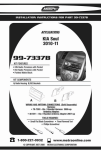
INSTALLATION INSTRUCTIONS FOR PART 99-7318
APPLICATIONS
2005-2006 Kia Spectra 5
99-7318
KIT FEATURES
• DIN Head Unit Provision
• ISO DIN Head Unit Provision
KIT COMPONENTS
A) Radio Housing l B) ISO Brackets l C) ISO Trim plate
A
B
C
TOOLS REQUIRED:
Phillips Screwdriver • Small Flat Blade Screwdriver
1-800-221-0932
www.metraonline.com
© COPYRIGHT 2004-07 METRA ELECTRONICS CORPORATION
99-7318
TABLE OF CONTENTS
Dash Disassembly . . . . . . . . . . . . . . . . . . . . . . . . . . . . . . . . . . . 1
Kit Assembly . . . . . . . . . . . . . . . . . . . . . . . . . . . . . . . . . . . . . . 2, 3
Final Assembly . . . . . . . . . . . . . . . . . . . . . . . . . . . . . . . . . . . . . . 4
99-7318
DASH DISASSEMBLY
2005-2006 KIA SPECTRA 5
A
1
Disconnect the negative battery
terminal to prevent an accidental
short circuit.
2
Unclip and remove entire panel surrounding radio and including A/C
controls. (Figure A)
3
Remove (4) Phillips screws to extract
radio from dash. (Figure B)
B
1
99-7318
KIT ASSEMBLY
2005-2006 KIA SPECTRA 5
DIN HEAD UNIT PROVISION
1
Slide the DIN cage into the Radio
Housing and secure by bending the
metal locking tabs down. (Figure A)
2
Slide the aftermarket head unit into
the cage and secure. (Figure B)
A
B
2
99-7318
KIT ASSEMBLY
2005-2006 KIA SPECTRA 5
ISO DIN HEAD UNIT PROVISION
1
Mount the ISO bracket to the head
unit with screws supplied with the
unit. (Figure A)
2
Slide the head unit into the radio
opening until the side clips engage.
(Figure B)
3
Snap the trim plate into the radio
housing. (Figure B)
A
B
3
99-7318
FINAL ASSEMBLY
FINAL ASSEMBLY
A
B
C
A)
Strip wire ends back 1/2"
B)
Twist ends together
C)
Solder
D)
Tape
D
1
Locate the factory wiring harness in the dash. Metra recommends using the
proper mating adapter and making connections as shown.
(Isolate and individually tape off the ends of any unused wires to prevent
electrical short circuit.)
2
3
Re-connect the negative battery terminal and test the unit for proper operation.
Reassemble radio and dash assemblies in reverse order of disassembly.
FINAL WIRING CONNECTIONS
Make wiring connections using the EIA color code chart shown below and the instructions included with the head
unit. Metra recommends making connections as shown below; Strip, Splice, Solder, Tape. Isolate and individually
tape off ends of any unused wires to prevent electrical short circuit.
METRA / EIA WIRING CODE
12V Ignition / Acc . . . Red
12V Batt / Memory . . Yellow
Ground . . . . . . . . . . . Black*
Power Antenna . . . . . Blue
Amp Turn-On . . . . . . Blue / White
Amp Ground . . . . . . . Black / White
Illumination. . . . . . . . Orange
Dimmer . . . . . . . . . . Orange / White
Right Front (+) . . . . . Gray
Right Front (-). . . . . . Gray / Black
Left Front (+) . . . . . . White
Left Front (-) . . . . . . . White / Black
Right Rear (+). . . . . . Violet
Right Rear (-) . . . . . . Violet / Black
Left Rear (+). . . . . . . Green
Left Rear (-) . . . . . . . Green / Black
*NOTE: When Black a wire is not present, ground radio to vehicle chassis.
All colors may not be present on all leads due to manufacturer’s specifications.
4
99-7318
NOTES
5
FINAL ASSEMBLY
99-7318 INSTRUCTIONS
1-800-221-0932
REV. 08/24/07
www.metraonline.com
© COPYRIGHT 2004-07 METRA ELECTRONICS CORPORATION
INST99-7318