1
M-class
Operator’s Manual
ML 320
ML 430
ML 55 AMG
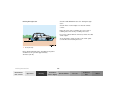
Our company and staff congratulate you on the purchase of your new Mercedes-Benz.
Your selection of our product is a demonstration of your trust in our company name. Further, it exemplifies your desire
to own an automobile that will be as easy as possible to operate and provide years of service.
Your Mercedes-Benz represents the efforts of many skilled engineers and craftsmen. To ensure your pleasure of
ownership, and for your safety and that of your passengers, we ask you to make a small investment of your time:
• Please read this manual carefully before putting it aside. Then return it to your vehicle where it will be handy for
your reference.
• Please abide by the recommendations contained in this manual. They are designed to acquaint you with the
operation of your Mercedes-Benz.
• Please abide by the warnings and cautions contained in this manual. They are designed to help improve the safety
of the vehicle operator and occupants.
We extend our best wishes for many miles of safe, pleasurable driving.
DaimlerChrysler AG
Introduction
Product information .......................... 7
Roadside assistance ......................... 10
Where to find it ................................ 14
Reporting Safety Defects ................ 16
Instruments and controls
Instruments and controls ............... 18
Center console ..............................20
Overhead control panel ............... 21
Operation
Vehicle keys ...................................... 24
Start lock-out ....................................25
General notes on the
central locking system ...............26
Central locking system ................... 26
Radio frequency
remote control ..............................26
Unlocking the liftgate ..................28
Panic button ..................................28
Mechanical keys ...........................29
Contents
Doors ................................................. 30
Central locking switch .................... 32
Automatic central locking .......... 32
Emergency unlocking in case
of accident ................................... 33
Liftgate .............................................. 34
Antitheft alarm system ................... 35
Tow-away alarm and
glass breakage sensor ............... 36
Seats, front ....................................... 37
Manual seats ................................ 39
Power seats ................................... 40
Head restraint ...............................41
Heated seats ..................................... 44
Seat belts and integrated
restraint system .......................... 46
Seat belts .......................................... 46
Seat belt nonusage
warning system ............................ 47
BabySmartTM airbag
deactivation system ................... 53
Self-test BabySmartTM
without special child
seat installed ................................ 53
1
Supplemental restraint
system (SRS) ................................54
Emergency tensioning
retractor (ETR) ............................. 55
Airbags ..............................................56
Safety guidelines for the
seat belt, emergency
tensioning retractor
and airbag .....................................63
Infant and child
restraint systems ..........................65
Adjustable steering wheel ..............70
Inside rear view mirror .................. 71
Antiglare night position .............. 71
Exterior rear view mirrors .............73
Exterior rear view mirror,
electrically folding .......................75
Instrument cluster ........................... 76
Indicator lamps in the
instrument cluster ...................... 78
Trip computer ...................................83
Flexible service system (FSS) ........87
Engine oil level indicator ................89
Exterior lamp switch .......................90
Contents
2
Fog lamp switch
(except Canada) ...........................92
Fog lamp switch
(Canada only) ..............................93
Hazard warning flasher
switch ............................................94
Headlamp cleaning system ............ 94
Windshield wiper/washer
switch ............................................95
Rear window wiper/washer ...........96
Climate control ................................. 98
Basic setting – Heater ............... 100
Basic setting –
Air conditioner ........................... 100
Special setting ............................ 101
Dust filter .................................... 102
Air recirculation ......................... 102
Rear window defroster .............. 103
Power windows ............................... 104
Rear quarter windows ................... 106
Sliding/pop-up roof ....................... 107
Skyview Top .................................... 109
Interior lighting ..............................110
Sun visors ........................................113
Illuminated vanity mirrors ........... 113
Interior ............................................. 114
Storage compartments,
armrest and cup holder ............ 114
Glove box ...................................... 115
Armrest in rear bench seat ........... 117
Ashtrays ........................................... 118
Lighter .............................................. 119
Split rear seat bench ..................... 120
Easy entry/exit feature ............. 123
Rear seat head restraints ......... 124
Third row seats .............................. 126
Removable cargo floor plates ...... 129
Enlarged cargo area .......................131
Cargo tie-down rings .....................132
Hooks ...............................................133
Partition net ....................................133
Loading instructions ......................136
Cargo area cover blind ..................137
Telephone, general .........................139
Cellular telephone ..........................139
Garage door opener ....................... 140
Driving
Control and operation of
radio transmitters ..................... 146
The first 1 000 miles
(1 500 km) ................................. 147
Maintenance ................................... 147
Tele Aid ........................................... 148
Catalytic converter ........................ 160
Emission control ............................ 161
Steering lock ................................... 162
Starting and turning off
the engine .................................. 164
Automatic transmission ............... 165
Parking brake ................................. 173
Driving instructions ...................... 174
Drive sensibly – save fuel ......... 174
Drinking and driving ................. 174
Pedals ........................................... 174
Power assistance ........................ 175
Brakes .......................................... 175
Driving off ................................... 176
Parking ........................................ 176
Tires ............................................. 177
Snow chains ................................ 179
Winter driving instructions ...... 180
Deep water .................................. 181
Passenger compartment ........... 182
Traveling abroad ........................ 182
Off-Road driving ............................. 183
Trailer towing ................................. 190
Cruise control ................................. 196
Brake assist system (BAS) ............ 199
Antilock brake system (ABS) .......201
Four-wheel electronic
traction system (4-ETS+) ..........203
Electronic brake
proportioning (EBP) ..................204
Electronic stability program
(ESP) ...........................................205
Transmission control –
LOW RANGE mode ...................209
What you should know
at the gas station ....................... 212
Check regularly and
before a long trip ....................... 215
Contents
Instrument cluster display
Malfunction and indicator
lamps in the
instrument cluster .....................218
On-board diagnostic system –
Check engine malfunction
indicator lamp .............................218
Brake warning lamp ...................219
Supplemental restraint system
(SRS) indicator lamp ..................219
Fuel reserve warning ................ 220
Electronic stability
program (ESP) / Electronic
traction system (ETS) –
warning lamp ............................. 221
BAS/ESP malfunction
indicator lamp ............................ 221
4-ETS malfunction
indicator lamp ............................ 221
LOW RANGE
indicator lamp ............................ 221
ABS malfunction
indicator lamp ............................ 222
3
Adjustable steering wheel –
indicator lamp .............................222
AIRBAG OFF
indicator lamp .............................222
Seat belt warning lamp .............223
Charge indicator lamp ...............223
Low engine oil level
warning lamp ..............................224
Low engine coolant
level warning ..............................224
Brake pad wear
indicator lamp .............................225
FSS indicator ...............................225
Contents
4
Practical hints
First aid kit .....................................228
Fuses ................................................228
Electrical outlet ..............................230
Stowing things in the vehicle ......230
Hood .................................................231
Checking engine oil level .............233
Automatic transmission
fluid level ...................................234
Engine oil consumption ................234
Coolant level ...................................234
Adding coolant ...........................235
Windshield washer/headlamp
cleaning system .........................236
Windshield and
headlamp washer fluid
mixing ratio ................................237
Vehicle jack, wheel bolt
wrench and screwdriver ......... 237
Air pump ......................................... 239
Wheels ............................................ 240
Tire replacement ....................... 240
Rotating wheels ......................... 241
Spare wheel .................................... 242
Changing wheels ........................... 245
Tire inflation pressure ................. 250
Battery ............................................. 251
Jump starting ................................. 253
Towing the vehicle ........................ 255
Transmission selector lever,
manually unlocking .................. 259
Stranded vehicle ............................ 259
Exterior lamps ................................260
Headlamp assembly ................... 261
Taillamp assemblies ..................265
Adjusting headlamp aim ...............268
Remote control
battery replacement .................270
Synchronizing
remote control ............................ 271
Emergency operation of
sliding/pop-up roof ...................272
Emergency operation of
Skyview Top ...............................273
Manual release for
fuel filler flap ............................. 274
Replacing wiper blades .................275
Roof rack ......................................... 276
Vehicle care
Cleaning and care
of the vehicle .............................278
Power washer ..............................279
Tar stains .....................................279
Paintwork, painted body
components .................................279
Engine cleaning ..........................280
Vehicle washing .........................280
Ornamental moldings ................280
Headlamps, taillamps,
turn signal lenses ......................280
Window cleaning ........................ 281
Wiper blades ............................... 281
Light alloy wheels ......................281
Instrument cluster ..................... 281
Steering wheel and
gear selector lever ......................281
Contents
Cup holder .................................. 282
Seat belts ..................................... 282
Headliner .................................... 282
Upholstery .................................. 282
Hard plastic trim items ............. 282
Plastic and rubber parts ........... 282
Brake fluid ......................................294
Premium unleaded gasoline ........295
Fuel requirements .........................295
Gasoline additives .........................296
Coolants ...........................................296
Consumer information ..................298
Technical data
Index
Spare parts service ....................... 284
Warranty coverage ........................ 284
Identification labels ...................... 285
Layout of poly-V-belt drive ........... 286
Technical data ................................ 287
Fuels, coolants, lubricants
etc. – capacities ........................ 292
Engine oils ...................................... 294
Engine oil additives ...................... 294
Air conditioner refrigerant .......... 294
Index ................................................300
5
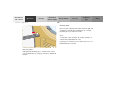
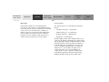
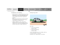
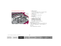
Product information
Kindly observe the following in your own best interest:
We recommend using Mercedes-Benz original parts as well as conversion parts and accessories
explicitly approved by us for your vehicle model.
We have tested these parts to determine their reliability, safety and their special
suitability for Mercedes-Benz vehicles.
We are unable to make an assessment for other products and therefore cannot be held responsible
for them, even if in individual cases an official approval or authorization by governmental or other
agencies should exist. Use of such parts and accessories could adversely affect the safety,
performance or reliability of your vehicle. Please do not use them.
Mercedes-Benz original parts as well as conversion parts and accessories approved by us are available
at your authorized Mercedes-Benz Light Truck Center where you will receive comprehensive information, also on
permissible technical modifications, and where proper installation will be performed.
Introduction
7
Introduction
8
Operator’s manual
This Operator’s Manual contains a great deal of useful information. We urge you to read it carefully and familiarize
yourself with the vehicle before driving.
For your own safety and longer service life of the vehicle, we urge you to follow the instructions and warnings
contained in this manual. Ignoring them could result in damage to the vehicle or personal injury to you or others.
Vehicle damage caused by failure to follow instructions is not covered by the Mercedes-Benz Limited Warranty.
Your vehicle may have some or all of the equipment described in this manual. Therefore, you may find explanations
for optional equipment not installed in your vehicle. If you have any questions about the operation of any equipment,
your authorized Mercedes-Benz Light Truck Center will be glad to demonstrate the proper procedures.
Service and warranty information
The Service and Warranty Information Booklet contains detailed information about the warranties covering your
Mercedes-Benz, including:
• New Light Truck Limited Warranty,
• Emission System Warranty,
• Emission Performance Warranty,
• California, Maine, Massachusetts, and Vermont Emission Control System Warranty
(California, Maine, Massachusetts, and Vermont only),
• State Warranty Enforcement Laws (Lemon Laws).
Important notice for California retail buyers of Mercedes-Benz automobiles
Under California law you may be entitled to a replacement of your vehicle or a refund of the purchase price, if
Mercedes-Benz USA, LLC or its authorized Mercedes-Benz Center fails to conform the vehicle to its express warranties
after a reasonable number of repair attempts during the period of one year or 12 000 miles from original delivery of
the vehicle. A reasonable number of repair attempts is presumed for a retail buyer (1) if the vehicle is out of service by
reason of repair of substantial nonconformities for a cumulative total of more than 30 calendar days or (2) the same
substantial non-conformity has been subject to repair four or more times and you have at least once directly
notified us in writing of the need to repair the non-conformity and have given us an opportunity to perform the
repair ourselves. Notifications should be sent to the nearest Mercedes-Benz Regional Office listed in the
Service and Warranty Information Booklet.
Maintenance
The Service Booklet describes all the necessary maintenance work which should be performed at regular intervals.
Always have the Service Booklet with you when you take the vehicle to your authorized Mercedes-Benz Light Truck
Center for service. The service advisor will record each service in the booklet for you.
Introduction
9
Introduction
10
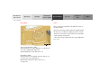
Roadside assistance
The Mercedes-Benz Roadside Assistance Program provides factory trained technical help in the event of a breakdown.
Calls to the toll-free Roadside Assistance number:
1-800-FOR-MERCedes (in the USA)
1-800-387-0100 (in Canada)
will be answered by Mercedes-Benz Client Assistance Representatives 24 hours a day, 365 days a year.
Roadside assistance will be provided in accordance with standard program guidelines which include providing service
to the vehicle up to a reasonable distance from a paved roadway. We will make every effort to assist in a breakdown
situation, however, the accessibility of your vehicle will be determined by our authorized Mercedes-Benz Light Truck
Center technician or the tow service provider on a case by case basis and may be a factor in our ability to respond.
Additional charges may be applicable for a breakdown location determined not to be a reasonably accessible roadside
location as determined by our authorized technician and tow service provider.
For additional information refer to the Mercedes-Benz Roadside Assistance Program brochure in your glove box.
Change of address or ownership
If you change your address, be sure to send in the “Change of Address Notice” found in the Service and Warranty
Information Booklet, or simply call the Mercedes-Benz Client Assistance Center (in the USA) at
1-800-FOR-MERCedes, or Customer Service (in Canada) at 1-800-387-0100. It is in your own interest that we can
contact you should the need arise.
If you sell your Mercedes, please leave all literature with the vehicle to make it available to the next operator.
If you bought this vehicle used, be sure to send in the “Notice of Purchase of Used Car” found in the Service and
Warranty Information Booklet, or call the Mercedes-Benz Client Assistance Center (in the USA) at
1-800-FOR-MERCedes, or Customer Service (in Canada) at 1-800-387-0100.
Operating your vehicle outside the USA or Canada
If you plan to operate your vehicle in foreign countries, please be aware that:
• Service facilities or replacement parts may not be readily available,
• unleaded gasoline for vehicles with catalytic converters may not be available; the use of leaded fuels will damage
the catalysts,
• gasoline may have a considerably lower octane rating, and improper fuel can cause engine damage.
Introduction
11
Introduction
12
We continuously strive to improve our product, and ask for your understanding that we reserve the right to make
changes in design and equipment. Therefore, information, illustrations and descriptions in this Operator’s Manual
might differ from your vehicle.
Optional equipment is also described in this manual, including operating instructions wherever necessary. Since they
are special-order items, the descriptions and illustrations herein may vary slightly from the actual equipment of your
vehicle.
If there are any equipment details that are not shown or described in this Operator’s Manual, your authorized
Mercedes-Benz Light Truck Center will be glad to inform you of correct care and operating procedures.
The Operator’s Manual and Service Booklet are important documents and should be kept with the vehicle.
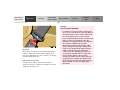
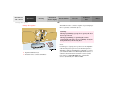
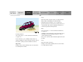
Warning!
This Sport Utility Vehicle is designed for both on-road and off-road use. It can go places and perform tasks for
which conventional 2-wheel drive passenger cars were not intended. This vehicle will handle and maneuver
differently from conventional passenger cars in driving conditions which may occur on streets, highways and
off-road use.
This vehicle has a higher ground clearance and a higher center of gravity than many passenger cars. As with
other vehicles of this type, if you make sharp turns at excessive speeds or abrupt maneuvers, the vehicle may
roll over or may go out of control and crash. Utility vehicles have a significantly higher rollover rate than
other types of vehicles. Failure to operate this vehicle safely may result in an accident, rollover of the vehicle,
and severe or fatal injury.
Before you start to drive this vehicle, read the Operator’s Manual. Take time to become familiar with the
driving characteristics of this vehicle. Be sure you are familiar with all vehicle controls. Learn how your
vehicle handles on different road surfaces. Do not attempt sharp turns at excessive speeds or abrupt
maneuvers or other unsafe driving actions that can cause loss of vehicle control. When driving off-road or
working the vehicle, do not overload it. And, always wear your seat belts at all times. In a rollover crash, an
unbelted person is significantly more likely to die than a person wearing a seat belt.
Introduction
13
Introduction
14
Where to find it
The Operator’s Manual is divided into eight sections:
• Instruments and controls: An overview of all the controls that can be operated from the driver’s seat.
• Operation: Information on the vehicle’s equipment and its operation.
• Driving: Important information on driving.
• Instrument cluster display: Indicator lamps on the instrument cluster with brief instructions.
• Practical hints: Assistance and instructions in the event of an emergency.
• Car care: Instructions on caring for your vehicle.
• Technical data: All the important technical data for your vehicle as well as consumer information such as fuels,
coolants, lubricants etc. is contained here.
• Index: Key terms to help you find a topic quickly.
Other documents may also be supplied, depending on your vehicle’s equipment.
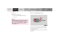
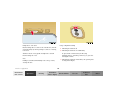
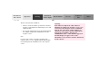
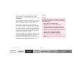
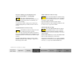
Explanation of color used:
Warning notices for the protection of yourself and
others appear on red background.
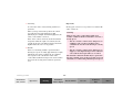
Problems with your vehicle
If you should experience a problem with your vehicle, particularly one that you believe may affect
its safe operation, we urge you to immediately contact your authorized Mercedes-Benz Light Truck
Center to have the problem diagnosed and corrected if required. If the matter is not handled to
your satisfaction, please discuss the problem with the Mercedes-Benz Light Truck Center
management, or if necessary contact us at the following addresses:
In the USA:
In Canada:
Introduction
Client Assistance Center
Mercedes-Benz USA, LLC
One Mercedes Drive
Montvale, NJ 07645-0350
Customer Relations Department
Mercedes-Benz Canada, Inc.
849 Eglinton Avenue East
Toronto, Ontario, M4G 2L5
15
Introduction
16
For the USA only:
The following text is published as required of manufacturers under Title 49, Code of U.S. Federal Regulations,
Part 575 pursuant to the “National Traffic and Motor Vehicle Safety Act of 1966”.
Reporting Safety Defects
If you believe that your vehicle has a defect which could cause a crash or could cause injury or
death, you should immediately inform the National Highway Traffic Safety Administration
(NHTSA) in addition to notifying Mercedes-Benz USA, LLC.
If NHTSA receives similar complaints, it may open an investigation, and if it finds that a safety
defect exists in a group of vehicles, it may order a recall and remedy campaign. However, NHTSA
cannot become involved in individual problems between you, your retailer, or
Mercedes-Benz USA, LLC.
To contact NHTSA, you may either call the Auto Safety Hotline toll-free at 1-800-424-9393
(or 366-0123 in Washington, D.C. area) or write to: NHTSA, U.S. Department of Transportation,
Washington, D.C. 20590. You can also obtain other information about motor vehicle safety from
the Hotline.
Instruments and controls
Instruments and controls ............... 18
Center console ..............................20
Overhead control panel ............... 21
Contents - Instruments and controls
Instruments
and controls
Operation
Driving
17
Instrument
cluster display
Practical hints
Car care
Technical
data
Index
Instruments
and controls
Operation
Driving
Instruments and controls
Instruments and controls
Instrument
cluster display
Practical hints
18
Car care
Technical
data
Index
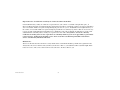
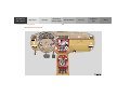
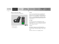
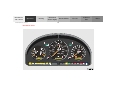
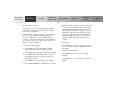
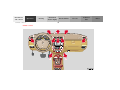
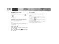
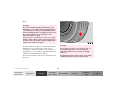
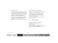
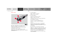
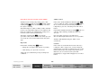
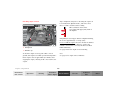
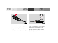
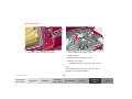
14 Transmission control – LOW RANGE mode, see
page 209
For more detailed descriptions see index on page 300.
For adjustment of air outlets, refer to climate control,
see page 98.
15 Indicator lamp for antitheft alarm system
16 Auxiliary front fog lamp/rear fog lamp switch, see
page 92
1 Cup holder, see page 114
2 Parking brake release, see page 173
3 Parking brake pedal, see page 173
17 MCS (Optional Modular Control System), see
separate operator’s manual
4 Steering wheel adjustment lever, see page 70
18 Front passenger airbag, see page 56
5 Headlamp washer switch, see page 94
6 Exterior lamp switch, see page 90
19 Glove box (illuminated with key in steering lock
position 1 or 2)
7 Cruise control switch, see page 196
20 Cup holder, see page 114
8 Instrument cluster, see page 76
21 Storage compartment
9 Hazard warning flasher switch, see page 94
22 Air recirculation switch, see page 98
10 Horn (with key in steering lock position 1 or 2),
Driver airbag, see page 56
23 Air conditioner on /off switch, see page 98
11 Steering lock with ignition /starter switch, see
page 162
25 Temperature selector switch
12 Switch for exterior rear view mirrors, electrically
folding, see page 75
27 Electrical outlet, see page 230
24 Air volume control switch
26 Air distribution switch
13 Windshield wiper /washer switch, see page 95
Instruments and controls
Instruments
and controls
Operation
19
Driving
Instrument
cluster display
Practical hints
Car care
Technical
data
Index
Instruments
and controls
Operation
Instruments and controls
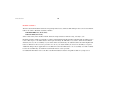
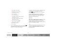
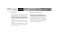
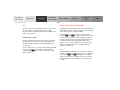
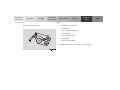
Center console
Driving
Instrument
cluster display
Practical hints
Car care
Technical
data
20
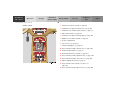
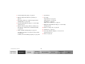
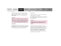
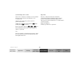
1 Left front seat heater switch, see page 44
2 Switch for rear quarter window, left, see page 106
3 Switch for rear window washer/wiper, see page 96
4 ESP control switch, see page 207
5 Switch for rear quarter window, right, see page 106
6 Right front seat heater switch, see page 44
7 Storage compartment
8 Selector lever, see page 165
9 Ashtray with lighter, see page 118
10 Power window switch, left front door, see page 104
11 Central locking switch, see page 32
12 Rear window defroster switch, see page 103
13 Power window switch, right front door, see page 104
14 Power window switch, left rear door, see page 104
15 Mirror adjustment switch, see page 73
16 Power window safety switch, rear doors, see
page 104
17 Power window switch, right rear door, see page 104
Index
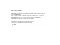
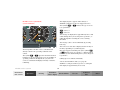
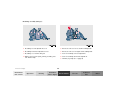
Overhead control panel
1 Interior lighting, see page 110
2 Garage door opener, see page 140
3 Hands-free microphone for Tele Aid, telephone and
voice recognition system
4 Tele Aid (emergency call system), see page 148
2
1
5 Sliding/pop-up roof, see page 107
Skyview Top, see page 109
1
6 Rear view mirror, see page 71
Reading lamps inside rear view mirror, see page 110
3
4
5
6
Instruments and controls
Instruments
and controls
Operation
21
Driving
Instrument
cluster display
Practical hints
Car care
Technical
data
Index
Instruments
and controls
Operation
Driving
Contents - Operation
Operation
Vehicle keys ...................................... 24
Start lock-out ....................................25
General notes on the
central locking system ...............26
Central locking system ................... 26
Radio frequency
remote control ..............................26
Unlocking the liftgate ..................28
Panic button ..................................28
Mechanical keys ...........................29
Doors .................................................. 30
Central locking switch ....................32
Automatic central locking ..........32
Emergency unlocking in case
of accident ....................................33
Liftgate ............................................... 34
Antitheft alarm system ................... 35
Tow-away alarm and
glass breakage sensor ................ 36
Seats, front ........................................ 37
Manual seats ................................. 39
Power seats ................................... 40
Instrument
cluster display
Practical hints
Car care
Technical
data
22
Head restraint ...............................41
Heated seats ..................................... 44
Seat belts and integrated
restraint system .......................... 46
Seat belts .......................................... 46
Seat belt nonusage
warning system ............................ 47
BabySmartTM airbag
deactivation system ................... 53
Self-test BabySmartTM
without special child
seat installed ................................ 53
Supplemental restraint
system (SRS) ............................... 54
Emergency tensioning
retractor (ETR) ............................ 55
Airbags .............................................. 56
Safety guidelines for the
seat belt, emergency
tensioning retractor
and airbag ..................................... 63
Infant and child
restraint systems ......................... 65
Adjustable steering wheel .............. 70
Inside rear view mirror ...................71
Antiglare night position .............. 71
Exterior rear view mirrors .............73
Exterior rear view mirror,
electrically folding .......................75
Instrument cluster ........................... 76
Indicator lamps in the
instrument cluster ...................... 78
Trip computer ...................................83
Flexible service system (FSS) ........87
Engine oil level indicator ................89
Exterior lamp switch .......................90
Fog lamp switch
(except Canada) ..........................92
Fog lamp switch
(Canada only) ..............................93
Hazard warning flasher
switch ............................................94
Headlamp cleaning system ............ 94
Windshield wiper/washer
switch ............................................95
Rear window wiper/washer ...........96
Climate control .................................98
Basic setting – Heater ............... 100
Index
Basic setting –
Air conditioner ........................... 100
Special setting ............................ 101
Dust filter .................................... 102
Air recirculation ......................... 102
Rear window defroster .............. 103
Power windows ............................... 104
Rear quarter windows ................... 106
Sliding/pop-up roof ....................... 107
Skyview Top .................................... 109
Interior lighting ..............................110
Sun visors ........................................113
Illuminated vanity mirrors ........... 113
Interior ............................................. 114
Storage compartments,
armrest and cup holder ............ 114
Glove box ...................................... 115
Armrest in rear bench seat ........... 117
Ashtrays ........................................... 118
Lighter .............................................. 119
Split rear seat bench ..................... 120
Easy entry/exit feature ............. 123
Rear seat head restraints ......... 124
Third row seats .............................. 126
Contents - Operation
Instruments
and controls
Operation
Removable cargo floor plates .......129
Enlarged cargo area ....................... 131
Cargo tie-down rings ..................... 132
Hooks ............................................... 133
Partition net .................................... 133
Loading instructions ..................... 136
Cargo area cover blind .................. 137
Telephone, general ........................ 139
Cellular telephone ......................... 139
Garage door opener ....................... 140
23
Driving
Instrument
cluster display
Practical hints
Car care
Technical
data
Index
Instruments
and controls
Operation
Driving
Instrument
cluster display
Central locking system
Vehicle keys
Practical hints
Car care
Technical
data
24
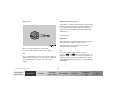
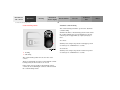
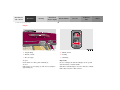
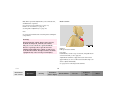
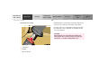
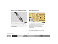
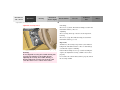
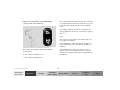
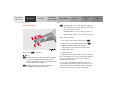
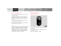
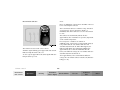
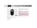
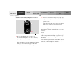
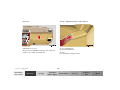
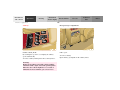
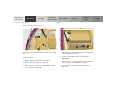
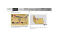
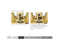
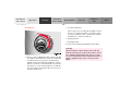
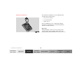
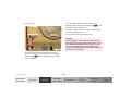
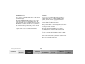
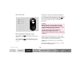
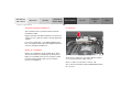
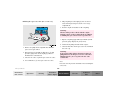
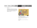
Remote control with folding master key
Included with your vehicle are:
• 2 remote controls with folding master keys,
• 1 reserve key,
Warning!
1
When leaving the vehicle always remove the key
from the steering lock, and lock your vehicle. Do
not leave children unattended in the vehicle, or
with access to an unlocked vehicle. Unsupervised
use of vehicle equipment may cause serious
personal injury.
The remote control operates all locks on the vehicle.
To release the key, press button (1). The key unfolds
from the holder by itself.
The transmitter for the remote control is located in the
key holder.
Index
Reserve key
Obtaining replacement keys
Your vehicle is equipped with a theft deterrent locking
system requiring a special key manufacturing process.
For security reasons, replacement keys can only be
obtained from your authorized Mercedes-Benz Light
Truck Center.
Start lock-out
Important!
Removing the key from the steering lock activates the
start lock-out. The engine cannot be started.
Turning the key in the steering lock to position 2
deactivates the start lock-out.
The reserve key fits all locks on the vehicle.
Note:
For notes on the mechanical keys refer to page 29.
In case the engine cannot be started and the
messages Á and î are shown in the odometer
display field, the system is not operational. Contact an
authorized Mercedes-Benz Light Truck Center or call
1-800-FOR-MERCedes (in the USA), or 1-800-387-0100
(in Canada).
Note:
We recommend that you carry the reserve key with you
and keep it in a safe place (e.g. your wallet) so that it is
always handy. Never leave the reserve key in the
vehicle.
Central locking system
Instruments
and controls
Operation
25
Driving
Instrument
cluster display
Practical hints
Car care
Technical
data
Index
Instruments
and controls
Operation
Driving
Instrument
cluster display
Central locking system
Practical hints
Car care
26
General notes on the central locking system
Central locking system
If the key in the steering lock is in position 1 or 2, the
vehicle cannot be locked or unlocked with the remote
control.
(Radio frequency remote control)
If the vehicle cannot be locked or unlocked:
• Check the batteries of the remote control, see
page 270.
• Synchronize the remote control, see page 271.
Technical
data
The master key has an integrated radio frequency
remote control.
Due to the extended operational range of the remote
control, it could be possible to unintentionally lock or
unlock the vehicle by pressing the transmit button.
The vehicle doors, liftgate and fuel filler flap can be
centrally locked and unlocked via remote control.
With vehicle centrally locked, the liftgate can also be
unlocked by using the remote control.
If the key in the steering lock is in position 1 or 2, the
vehicle cannot be locked or unlocked with the remote
control.
Index
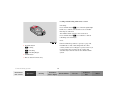
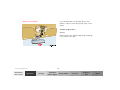
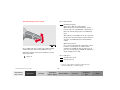
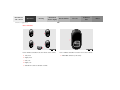
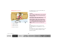
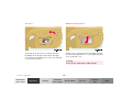
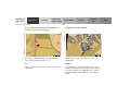
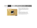
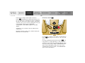
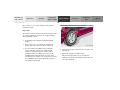
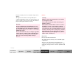
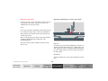
Locking and unlocking with remote control
Unlocking:
Press transmit button Πonce. All turn signal lamps
blink once to indicate that the driver’s door and fuel
filler flap are unlocked.
The antitheft alarm system is also deactivated.
Press transmit button Πa second time to unlock
remaining doors and liftgate.
Notes:
If the fuel filler flap cannot be opened, see page 274.
1 Transmit button
If within 40 seconds of unlocking with the remote
control, neither door nor liftgate is opened or the key is
not inserted in the steering lock, the vehicle will
automatically lock and reactivate the antitheft alarm
system.
‹ Locking
ΠUnlocking
Š Unlocking liftgate
2 PANIC button
3 Release button for master key
Central locking system
Instruments
and controls
Operation
27
Driving
Instrument
cluster display
Practical hints
Car care
Technical
data
Index
Instruments
and controls
Operation
Driving
Instrument
cluster display
Central locking system
Locking:
Practical hints
Car care
Technical
data
28
Panic button
Press transmit button ‹ once. All turn signal lamps
blink three times to indicate that the vehicle is locked
and the antitheft alarm is activated.
Notes:
If the turn signal lamps do not blink three times when
locking the vehicle, a door, the liftgate, or the hood is
not properly closed. Close the respective element and
lock the vehicle again with the remote control.
If the vehicle cannot be locked or unlocked by pressing
the transmit button, then it may be necessary to change
the batteries in the remote control or to synchronize the
remote control, see page 270 and page 271.
Unlocking the liftgate
Press transmit button Š to unlock the liftgate. This
also deactivates the antitheft alarm.
Important!
A minimum height clearance of 7 ft. (2.15 m) is
required to open the liftgate.
To activate press and hold button (1) for at least one
second. An audible alarm and blinking turn signal
lamps will operate for approximately 3 minutes.
Additionally the interior lights switch on automatically
for approximately 3 minutes.
To deactivate press button (1) again, or press transmit
button ‹, Œ or Š on the remote control, or
turn key in steering lock to position 1.
Index
Note:
Mechanical keys
For operation in the USA only: This device complies
with Part 15, Subpart C, Section 209 of the FCC Rules.
Operation is subject to the following two conditions:
The mechanical keys fit all locks on the vehicle.
(1) This device may not cause harmful interference, and
Use of the key does not operate the central locking
system or arm or disarm the antitheft alarm system.
Notes:
(2) this device must accept any interference received,
including interference that may cause undesired
operation.
The alarm sounds when unlocking the door. Cancel
alarm by turning key in steering lock to position 1, or
with the remote control by pressing button Œ.
WARNING: Changes or modification not expressly
approved by party responsible for compliance could void
the users’s authority to operate the equipment.
Central locking system
Instruments
and controls
Operation
29
Driving
Instrument
cluster display
Practical hints
Car care
Technical
data
Index
Instruments
and controls
Operation
Driving
Instrument
cluster display
Central locking system
Practical hints
Car care
Technical
data
30
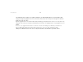
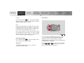
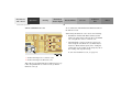
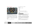
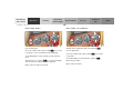
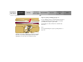
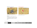
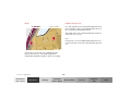
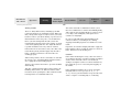
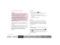
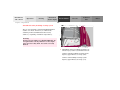
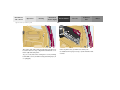
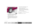
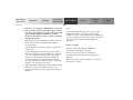
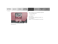
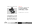
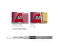
Doors
P72.10-2103-26
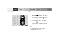
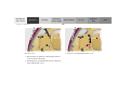
1 Opening – pull handle
2 Unlocking driver’s door lock
5 Front door from inside:
Pull handle to unlock.
3 Locking driver’s door lock
Important!
4 Individual door from inside:
Push lock button down to lock.
Pull lock button up to unlock.
The mechanical key does not operate the central locking
system or arm or disarm the antitheft alarm system.
When you lock the driver’s door with the mechanical
key, the door lock button should move down.
Index
Each individual door and the liftgate must be locked
with the respective door lock button – the driver’s door
can only be locked when it is closed.
To lock, push down lock buttons and turn mechanical
key in driver’s door lock to position 3. In addition lock
the liftgate.
Notes:
To unlock, pull inside door handles and turn mechanical
key in driver’s door lock to position 2.
The alarm sounds when unlocking the driver’s door.
Cancel alarm by turning key in steering lock to
position 1, or with the remote control by pressing
button Œ.
Rear doors, previously centrally locked, can be opened
from inside by first unlocking the vehicle with the
central locking switch, see page 32, or by first pulling
up the door lock button.
If the vehicle has previously been locked from the
outside, only the door being opened from the inside will
unlock, and the alarm will come on. The remaining
doors, the liftgate and fuel filler flap remain locked.
If the fuel filler flap cannot be opened, see page 274.
In case of a malfunction in the central locking system
the doors can be locked and unlocked individually.
Central locking system
Instruments
and controls
Operation
31
Driving
Instrument
cluster display
Practical hints
Car care
Technical
data
Index
Instruments
and controls
Operation
Driving
Instrument
cluster display
Central locking system
Central locking switch
Practical hints
Car care
Technical
data
32
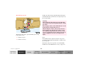
Automatic central locking
The central locking switch also operates the automatic
central locking.
With the automatic central locking system activated and
the engine running, the doors and trunk are locked at
vehicle speeds of approximately 9 mph (15 km/ h) or
more.
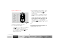
To activate:
With key in steering lock position 2 hold upper portion
of switch (1) for a minimum of 5 seconds.
To deactivate:
1 Locking
2 Unlocking
The central locking switch is located on the center
console.
The doors and trunk can only be locked with the central
locking switch, if the front doors are closed.
If the vehicle was previously locked with the remote
control, the doors and liftgate cannot be unlocked with
the central locking switch.
With key in steering lock position 2 hold lower portion
of switch (2) for a minimum of 5 seconds.
Index
Notes:
Emergency unlocking in case of accident
If doors are unlocked with the central locking switch
after activating the automatic central locking, and
neither door is opened, then the doors remain unlocked
even at vehicle speeds of approximately 9 mph
(15 km/ h) or more.
The doors unlock automatically a short time after an
accident in which an airbag or emergency tensioning
retractor deploys (this is intended to aid rescue and
exit). However, the key must still be in the steering lock
position 1 or 2.
If a door is opened from the inside at speeds of
approximately 9 mph (15 km/ h) or less with the
automatic central locking activated, the door will again
be automatically locked at speeds of approximately
9 mph (15 km /h) or more.
Additionally the hazard warning flashers turn on
automatically and the interior lights switch on for
approximately 30 minutes.
Important!
When towing the vehicle, or with the vehicle on a
dynamometer test stand, please, note the following:
With the engine running, the vehicle doors will lock if
the left front wheel spins at vehicle speeds of
approximately 9 mph (15 km/ h) or more.
To prevent vehicle door locks from locking, deactivate
the automatic central locking.
Central locking system
Instruments
and controls
Operation
33
Driving
Instrument
cluster display
Practical hints
Car care
Technical
data
Index
Instruments
and controls
Operation
Driving
Instrument
cluster display
Central locking system
Practical hints
Car care
Technical
data
34
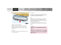
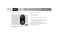
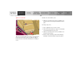
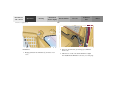
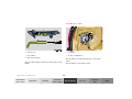
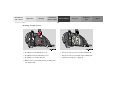
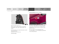
Liftgate
1 Grip molding
1 Handle, inside
2 Handle, outside
2 Locking
3 Recessed grip
3 Unlocking
To open:
From outside of vehicle, pull on handle (2).
To close:
Pull down on recessed grip (3), and close by using the
grip molding (1).
Important!
In case of danger, the unlocked liftgate can be opened
with the inside or outside handle.
Only drive with the liftgate closed as otherwise exhaust
fumes may enter the vehicle interior.
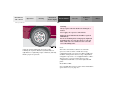
Index
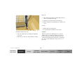
Antitheft alarm system
Operation:
The indicator lamp is located in the center console.
Once the alarm system has been armed, the turn signal
lamps will flash rapidly (approximately 3 minutes) and
the horn will sound intermittently (approximately
30 seconds) when someone:
The antitheft alarm is automatically armed or disarmed
with the remote control by locking or unlocking the
vehicle.
• opens a door,
The antitheft alarm is armed within approximately
15 seconds after locking the vehicle with the remote
control.
• opens the liftgate,
• opens the hood,
A blinking lamp in the center console indicates that the
alarm is armed.
• breaks a window,
• attempts to raise the vehicle.
Notes:
The alarm will stay on even if the activating element (a
door, for example) is immediately closed.
Use of the key in the front door locks does not arm or
disarm the antitheft alarm system.
If the alarm stays on for more than 20 seconds, an
emergency call is initiated automatically. See Tele Aid
on page 148.
The alarm sounds when unlocking the driver’s door
with the mechanical key. Cancel alarm by turning key in
steering lock to position 1, or with the remote control by
pressing button Œ.
Note:
If the vehicle battery voltage falls below 10 volts, the
alarm is automatically canceled and the antitheft alarm
system is disarmed. When the voltage is above this
value again, the antitheft alarm system is armed again.
Antitheft alarm system
Instruments
and controls
Operation
The alarm system will cycle three times when triggered.
The interior lights are automatically switched on when
the alarm comes on and go out when canceling the
alarm.
35
Driving
Instrument
cluster display
Practical hints
Car care
Technical
data
Index
Instruments
and controls
Operation
Driving
Instrument
cluster display
Tow-away protection
Tow-away alarm and glass breakage sensor
Practical hints
Car care
Technical
data
36
The alarm will last approximately 3 minutes in the form
of rapidly flashing turn signal lamps. At the same time
the horn will sound for approximately 30 seconds. The
alarm will stay on even if the vehicle is immediately
lowered.
If the alarm stays on for more than 20 seconds, an
emergency call is initiated automatically. See Tele Aid
on page 148.
To prevent triggering the tow-away alarm feature, switch
off the tow-away alarm and glass breakage sensor before
towing the vehicle, or when parking on a surface subject
to movement, such as a ferry or auto train.
The switch is located in the overhead console.
The tow-away alarm and glass breakage sensor are part
of the antitheft alarm system.
Once the alarm system has been armed, the turn signal
lamps will flash rapidly and the horn will sound when
someone attempts to raise the vehicle, or breaks a
window and reaches into the passenger compartment.
To do so, turn key in steering lock to position 1, then
return it to position 0 and remove key from steering
lock.
Within 30 seconds, push left or right button. (On
vehicles equipped with optional trip computer, push
RESET or MODE button, display shows OFF.)
Exit vehicle, and lock vehicle with remote control.
The tow-away alarm and glass breakage sensor remain
switched off until the key is inserted in steering lock
and turned to position 1.
Index
Seats, front
Warning!
Warning!
Do not adjust the driver’s seat while driving.
Adjusting the seat while driving could cause the
driver to lose control of the vehicle.
When leaving the vehicle always remove the key
from the steering lock, and lock your vehicle.
Do not leave children unattended in the vehicle or
with access to an unlocked vehicle. Unsupervised
use of vehicle equipment may cause serious
personal injury.
Never ride in a moving vehicle with the backrest
reclined. Sitting in an excessively reclined position
can be dangerous. You could slide under the seat
belt in a collision. If you slide under it, the belt
would apply force at the abdomen or neck. That
could cause serious or even fatal injuries. The
backrest and seat belt provide the best restraint
when the wearer is in an upright position and the
belt is properly positioned on the body.
Caution!
Do not remove head restraints except when mounting
seat covers. For removal see page 43. Whenever head
restraints have been removed be sure to reinstall them
before driving.
Never place hands under seat or near any moving
parts while a seat is being adjusted.
Seats
Instruments
and controls
37
Operation
Driving
Instrument
cluster display
Practical hints
Car care
Technical
data
Index
Instruments
and controls
Operation
Driving
Instrument
cluster display
Seats
Practical hints
Car care
Technical
data
38
Important!
Warning!
Prior to operating the vehicle, the driver should adjust
the seat height for proper vision as well as fore/ aft
placement and backrest angle to insure adequate
control, reach, operation, and comfort. The head
restraint should also be adjusted for proper height. See
also airbag section on page 56 for proper seat
positioning.
Children 12 years old and under must never ride in
the front seat, except in a Mercedes-Benz
authorized BabySmartTM compatible child seat,
which operates with the BabySmartTM system
installed in the vehicle to deactivate the passenger
side front airbag when it is properly installed.
Otherwise they will be struck by the airbag when it
inflates in a crash. If this happens, serious or fatal
injury can result.
In addition, also adjust the steering wheel to ensure
adequate control, reach, operation, and comfort.
Both the inside and outside rear view mirrors should be
adjusted for adequate rearward vision.
Fasten seat belts. Infants and small children should be
seated in a properly secured restraint system that
complies with U.S. Federal Motor Vehicle Safety
Standard 213 and Canadian Motor Vehicle Safety
Standard 213.
All seat, head restraint, steering wheel, and rear view
mirror adjustments as well as fastening of seat belts
should be done before the vehicle is put into motion.
According to accident statistics, children are safer
when properly restrained in the rear seating
positions than in the front seating positions.
Infants and small children must ride in the back
seats and be seated in an appropriate infant or
child restraint system, which is properly secured
with the vehicle’s seat belt, fully in accordance
with the child seat manufacturer’s instructions.
A child’s risk of serious or fatal injuries is
significantly increased if the child restraints are
not properly secured in the vehicle and the child is
not properly secured in the child restraint.
Index
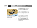
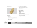
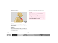
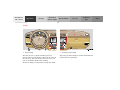
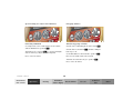
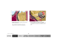
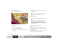
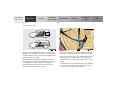
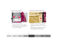
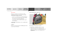
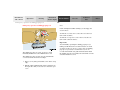
Manual seats (ML 320)
2 Seat cushion inclination adjustment
Raise lever (2), move seat cushion to desired
position. Release lever.
3 Backrest adjustment
Turn handwheel (3).
4 Head restraint height
Raising:
Pull up on head restraint.
Lowering:
Push button (4), located at top of seat back, and
push down on head restraint.
Adjust head restraint to support the back of the head
approximately at ear level. The head restraint angle
can also be adjusted manually.
We recommend to adjust the manual seat in the
following order:
See page 43 for removing head restraints.
1 Seat, fore/aft
Lift handle (1), slide seat to desired position and
allow handle to reengage. Check for proper
engagement before driving. The position should be
as far rearward as possible, consistent with ability to
properly operate controls.
Seats
Instruments
and controls
39
Operation
Driving
Instrument
cluster display
Practical hints
Car care
Technical
data
Index
Instruments
and controls
Operation
Driving
Instrument
cluster display
Seats
Practical hints
Car care
Technical
data
40
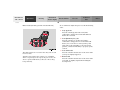
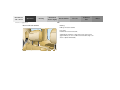
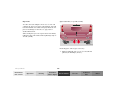
Power seats (standard; optional on model ML 320)
We recommend to adjust the power seat in the following
order:
1 Seat, up /down
Press the switch (up/down direction) until
comfortable seating position with still sufficient
headroom is reached.
2 Seat adjustment, fore /aft
Press the switch (fore/aft direction) until a
comfortable seating position is reached that still
allows you to reach the accelerator/brake pedal
safely. The position should be as far rearward as
possible, consistent with ability to properly operate
controls.
The slide switches are located on the entry side of each
front seat base.
3 Seat cushion tilt
Press the switch in the direction of the arrow until
your legs are lightly supported.
Turn key in steering lock to position 1 or 2 (with the
driver’s or passenger’s door open, the power seats can
also be operated with the key removed or in steering
lock position 0).
4 Backrest tilt
Press the switch in the direction of the arrow until
your arms are slightly angled when holding the
steering wheel.
Index
Head restraint
Only minor personal adjustments, as described below,
should then be required.
For exterior rear view mirrors, see page 73;
inside rear view mirror, see page 71;
steering wheel adjustment, see page 70.
Note:
See page 42 for instructions on storing and recalling the
seat position.
Warning!
When leaving the vehicle always remove the key
from the steering lock, and lock your vehicle.
The power seats can also be operated with the
driver’s or passenger door open. Do not leave
children unattended in the vehicle or with access
to an unlocked vehicle. Unsupervised use of vehicle
equipment may cause serious personal injury.
Raising:
Pull up on head restraint.
Lowering:
Push button, located at top of seat back, and push down
on head restraint, see also page 43.
Adjust head restraint to support the back of the head
approximately at ear level. The head restraint angle can
also be adjusted manually.
See page 43 for removing head restraints.
Seats
Instruments
and controls
41
Operation
Driving
Instrument
cluster display
Practical hints
Car care
Technical
data
Index
Instruments
and controls
Operation
Driving
Seats
Instrument
cluster display
Practical hints
Car care
Technical
data
42
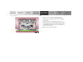
Memory storing and recalling
(optional on model ML 320 and ML 430)
Storing
Three sets of seat positions may be programmed into
memory. After the seat is positioned, push memory
button (5), release, and within 3 seconds push position
button “1”. A second and third set of positions for the
same seat can be programmed into memory by pushing
first memory button (5) and then position button “2”,
respectively “3”.
Recalling
To recall a seat position, push and hold one of the
position buttons “1”, “2” or “3” until seat movement has
stopped. The seat movement stops when the respective
position button is released.
5 Memory button
6 Position buttons
Caution!
Do not operate the power seats using the memory
button if the seat backrest is in an excessively reclined
position. Doing so could cause damage to front or rear
seats.
First move the backrest to an upright position.
Index
Head restraint removal
Ensure proper head restraint positioning, see above.
Warning!
For your protection, drive only with properly
positioned head restraints.
Adjust head restraint to support the back of the
head approximately at ear level.
Do not drive the vehicle without the seat head
restraints. Head restraints are intended to help
reduce injuries during an accident.
Removal:
Pull head restraint to its highest position. Push lock
button (arrow) and pull out head restraint completely
with both hands.
Installation:
Insert the head restraint and push it down to the stop.
Push lock button (arrow) and adjust head restraint down
to the desired position.
Seats
Instruments
and controls
43
Operation
Driving
Instrument
cluster display
Practical hints
Car care
Technical
data
Index
Instruments
and controls
Operation
Driving
Instrument
cluster display
Seats
Practical hints
Car care
Technical
data
44
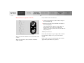
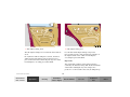
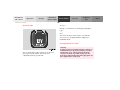
Heated seats (front, optional on ML 320)
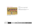
Press switch to turn on seat heater:
1 Normal seat heating mode. One indicator lamp in
the switch lights up.
1
2 Rapid seat heating mode. Both indicator lamps in
the switch light up.
After approximately 5 minutes in the rapid seat
heating mode, the seat heater automatically
switches to normal operation and only one indicator
lamp will stay on.
2
Turning off seat heater:
P54.25-2036-26
The front seat heater switches are located on the center
console.
The front seat heaters can be switched on with the
engine running.
If one indicator lamp is on, press upper half of switch.
If both indicator lamps are on, press lower half of
switch.
If left on, the seat heater automatically turns off after
approximately 20 minutes of operation.
Index
Notes:
When in operation, the seat heater consumes a large
amount of electrical power. It is not advisable to use the
seat heater longer than necessary.
The seat heaters may automatically switch off if too
many power consumers are switched on at the same
time, or if the battery charge is low. When this occurs,
the indicator lamps in the switch will blink for
approximately 30 seconds.
Within this time the seat heaters will switch on again
automatically as soon as sufficient voltage is available.
After approximately 30 seconds without sufficient
voltage the seat heaters switch off (indicator lamps go
out).
Seats
Instruments
and controls
45
Operation
Driving
Instrument
cluster display
Practical hints
Car care
Technical
data
Index
Instruments
and controls
Operation
Driving
Instrument
cluster display
Restraint systems
Practical hints
Car care
Technical
data
46
Seat belts and integrated restraint system
Warning!
Your vehicle is equipped with seat belts for all seats,
emergency tensioning retractors for front and second
row outboard seat belts, dual front airbags and door
mounted side impact airbags. Their protective functions
are designed to complement one another.
Children 12 years old and under must never ride in
the front seat, except in a Mercedes-Benz
authorized BabySmartTM compatible child seat,
which operates with the BabySmartTM system
installed in the vehicle to deactivate the passenger
side front airbag when it is properly installed.
Otherwise they will be struck by the airbag when it
inflates in a crash. If this happens, serious or fatal
injury will result.
Seat belts
Important!
Laws in most states and all Canadian provinces require
seat belt use.
All states and provinces require use of child restraints
that comply with U.S. Federal Motor Vehicle Safety
Standard 213 and Canadian Motor Vehicle Safety
Standard 213.
All child restraint systems are designed to be secured in
vehicle seats by lap belts or the lap belt portion of a lapshoulder belt.
For your safety and that of your passengers we strongly
recommend their use.
According to accident statistics, children are safer
when properly restrained in the rear seating
positions than in the front seating positions.
Infants and small children must ride in back seats
and be seated in an appropriate infant or child
restraint system, which is properly secured with
the vehicle’s seat belt, fully in accordance with the
child seat manufacturer’s instructions.
A child’s risk of serious or fatal injuries is
significantly increased if the child restraints are
not properly secured in the vehicle and the child is
not properly secured in the child restraint.
Index
Warning!
Warning!
Never ride in a moving vehicle with the backrest
reclined. Sitting in an excessively reclined position
can be dangerous. You could slide under the seat
belt in a collision. If you slide under it, the belt
would apply force at the abdomen or neck. That
could cause serious or even fatal injuries. The
backrest and seat belt provide the best restraint
when the wearer is in an upright position and the
belt is properly positioned on the body.
Failure to wear and properly fasten and position
your seat belt greatly increases your risk of
injuries and their likely severity in an accident.
You and your passengers should always wear seat
belts.
If you are ever in an accident, your injuries can be
considerably more severe without your seat belt
properly buckled. Without your seat belt buckled,
you are much more likely to hit the interior of the
vehicle or be ejected from it. You can be seriously
injured or killed.
Note:
For cleaning and care of the seat belts, see page 282.
In the same crash, the possibility for injury or
death is lessened if you are wearing your seat belt.
Seat belt nonusage warning system
Warning!
After starting the engine, a warning sounds and the seat
belt warning lamp < remains illuminated for a short
time if the driver’s seat belt is not fastened.
Restraint systems
Instruments
and controls
Operation
Never let more people ride in the vehicle than there
are seat belts available. Be sure everyone riding in
the vehicle is correctly restrained with a separate
seat belt.
47
Driving
Instrument
cluster display
Practical hints
Car care
Technical
data
Index
Instruments
and controls
Operation
Restraint systems
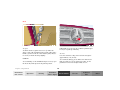
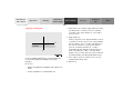
Fastening of seat belts
Driving
Instrument
cluster display
Practical hints
Car care
Technical
data
48
Push latch plate (1) into buckle (2) until it clicks. Do not
twist the belt. A twisted seat belt may cause injury.
To help avoid severe or fatal injuries, the lap belt must
be positioned as low as possible on your hips and not
across the abdomen.
Warning!
Always fasten your seat belt before driving off.
Always make sure your passengers are properly
restrained – even those sitting in the rear.
1 Latch plate
2 Buckle
3 Release button
Index
4 Button for belt outlet height adjustment
Tighten the lap portion to a snug fit by pulling shoulder
portion up.
To raise, slide belt height adjustment upward.
The shoulder portion of the seat belt must be pulled
snug and checked for snugness immediately after
engaging it.
To lower, press button (4) and slide belt outlet
downward.
Adjust seat belt so that shoulder portion is located as
close as possible to the middle of your shoulder (it
should not touch the neck). For this purpose, you can
adjust the height of the belt outlet. Three positions are
available.
Restraint systems
Instruments
and controls
Operation
Caution!
For safety reasons, avoid adjusting the seat or backrest
into positions which could affect the correct seat belt
positioning.
49
Driving
Instrument
cluster display
Practical hints
Car care
Technical
data
Index
Instruments
and controls
Operation
Driving
Instrument
cluster display
Restraint systems
Practical hints
Car care
Technical
data
50
Warning!
USE SEAT BELTS PROPERLY.
• Seat belts can only work when used properly.
Never wear seat belts in any other way than as
described in this section, as that could result
in serious injuries in case of an accident.
Operation
The inertia reel stops the belt from unwinding during
sudden vehicle stops or when quickly pulling on the
belt. The locking function of the reel may be checked by
quickly pulling out the belt.
Unfastening of seat belts
Push the release button (3) in the belt buckle (2).
Allow the retractor to completely rewind the seat belt by
guiding the latch plate (1).
• Each occupant should wear their seat belt at all
times, because seat belts help reduce the
likelihood of and potential severity of injuries
in accidents, including rollovers. The
integrated restraint system includes “SRS”
(driver airbag, front passenger airbag, front
and rear door mounted side impact airbags),
“ETR” (seat belt emergency tensioning
retractors for the outboard passenger seats
[except in the optional 3rd row seats]), and
front seat knee bolsters. The system is
designed to enhance the protection offered to
properly belted occupants in certain frontal
(front airbags) and side (side impact airbags)
impacts which exceed preset deployment
thresholds.
Index
• Never wear the shoulder belt under your arm,
against your neck or off your shoulder. In a
crash, your body would move too far forward.
That would increase the chance of head and
neck injuries. The belt would also apply too
much force to the ribs or abdomen, which
could severely injure internal organs such as
your liver or spleen.
• Each seat belt should never be used for more
than one person at a time. Do not fasten a seat
belt around a person and another person or
other objects.
• Belts should not be worn twisted. In a crash,
you wouldn’t have the full width of the belt to
manage impact forces. The twisted belt against
your body could cause injuries.
• Never wear belts over rigid or breakable
objects in or on your clothing, such as
eyeglasses, pens, keys etc., as these might
cause injuries.
• Pregnant women should also use a lapshoulder belt. The lap belt portion should be
positioned as low as possible on the hips to
avoid any possible pressure on the abdomen.
• Position the lap belt as low as possible on your
hips and not across the abdomen. If the belt is
positioned across your abdomen, it could cause
serious injuries in a crash.
Restraint systems
Instruments
and controls
Operation
• Never place your feet on the instrument panel
or on the seat. Always keep both feet on the
floor in front of the seat.
51
Driving
Instrument
cluster display
Practical hints
Car care
Technical
data
Index
Instruments
and controls
Operation
Driving
Instrument
cluster display
Restraint systems
Warning!
USE CHILD RESTRAINTS PROPERLY.
Children 12 years old and under must never ride in
the front seat, except in a Mercedes-Benz
authorized BabySmartTM compatible child seat,
which operates with the BabySmartTM system
installed in the vehicle to deactivate the passenger
front airbag when it is properly installed.
Otherwise they will be struck by the airbag when it
inflates in a crash. If this happens, serious or fatal
injury will result.
According to accident statistics, children are safer
when properly restrained in the rear seating
positions than in the front seating positions.
Infants and small children must ride in back seats
and be seated in an appropriate infant or child
restraint system, which is properly secured with
the vehicle’s seat belt, fully in accordance with the
child seat manufacturer’s instructions.
Practical hints
Car care
Technical
data
52
A child’s risk of serious or fatal injuries is
significantly increased if the child restraints are
not properly secured in the vehicle and the child is
not properly secured in the child restraint.
Children too big for child restraint systems must
ride in back seats using regular seat belts. Position
shoulder belt across chest and shoulder, not face or
neck. A booster seat may be necessary to achieve
proper belt positioning.
Index
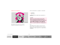
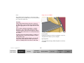
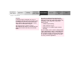
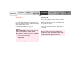
BabySmartTM airbag deactivation system
The passenger side front airbag will not deploy
only if the 7 indicator lamp remains
illuminated.
Special BabySmartTM compatible child seats, designed
for use with the Mercedes-Benz system and available at
any authorized Mercedes-Benz Center are required for
use with the BabySmartTM airbag deactivation system.
Please be sure to check the indicator every time
you use the special system child seat.
Should the light go out while the restraint is
installed, please check installation. If the light
remains out, do not use the BabySmartTM restraint
to transport children on the front passenger seat
until the system has been repaired.
With the special child seat properly installed, the
passenger front airbag will not deploy. The 7
indicator lamp located in the instrument cluster will be
illuminated, except with key removed or in steering lock
position 0. The system does not deactivate the door
mounted side impact airbag.
Warning!
Self-test BabySmartTM
without special child seat installed
The BabySmartTM Airbag Deactivation System will
ONLY work with a special child seat designed to
operate with it. It will not work with child seats
which are not BabySmartTM compatible.
After turning key in steering lock to position 1 or 2, the
7 indicator lamp located in the instrument cluster
comes on for approximately 6 seconds, extinguishes,
then blinks once.
Never place anything between seat cushion and
child seat (e.g. pillow), since it reduces the
effectiveness of the deactivation system.
If the indicator lamp should not come on or is
continuously lit, the system is not functioning. You must
see an authorized Mercedes-Benz Center before seating
any child on the front passenger seat.
Follow the manufacturer’s instructions for
installation of special child seats.
BabySmartTM is a trademark of Siemens Automotive Corp.
Restraint systems
Instruments
and controls
Operation
53
Driving
Instrument
cluster display
Practical hints
Car care
Technical
data
Index
Instruments
and controls
Operation
Driving
Instrument
cluster display
Restraint systems
Supplemental restraint system (SRS)
Airbags are intended as a supplement to seat belts.
Airbags alone cannot protect as well as airbags plus
seat belts in impacts for which the airbags were
designed to operate, and do not afford any protection
whatsoever in crashes for which the airbags are not
designed to deploy.
The SRS uses two crash severity levels (thresholds) to
activate either the Emergency Tensioning Retractor
(ETR) or front airbag or both. Activation depends on the
direction and severity of the impact exceeding the
preset thresholds and whether the seat belt is fastened.
Practical hints
Car care
Technical
data
54
Seat belt fastened
• first threshold exceeded: ETR activates
• second threshold exceeded: airbag also activates
Seat belt not fastened
Front seats:
• first threshold exceeded:
airbag activates, but not ETR
Rear outer seats:
• first threshold exceeded:
ETR activates
Driver, front passenger and rear outer seat systems
operate independently of each other.
Index
Emergency tensioning retractor (ETR)
In cases of other frontal impacts, angled impacts, rollovers, certain side impacts, or other accidents without
sufficient frontal or rear impact forces, the emergency
tensioning retractors will not be activated. The driver
and passengers will then be protected by the fastened
seat belts and inertia reel in the usual manner.
The seat belts for the outboard passenger seats (except
in the optional 3rd row seats) are equipped with
emergency tensioning retractors. These tensioning
retractors are located in each belt’s inertia reel and
become operationally ready with the key in steering
lock position 1 or 2.
For seat belt and emergency tensioning retractor see
page 63.
The emergency tensioning retractors are designed to
activate only when the seat belts are fastened during
frontal impacts exceeding the first threshold of the SRS
and in rear impacts exceeding a preset severity level.
They remove slack from the belts in such a way that the
seat belts fit more snugly against the body restricting its
forward movement as much as possible.
Restraint systems
Instruments
and controls
Operation
55
Driving
Instrument
cluster display
Practical hints
Car care
Technical
data
Index
Instruments
and controls
Operation
Driving
Instrument
cluster display
Restraint systems
Practical hints
Car care
Technical
data
56
Airbags
1 Driver airbag
The most effective occupant restraint system yet
developed for use in production vehicles is the seat belt.
In some cases, however, the protective effect of a seat
belt can be further enhanced by an airbag.
The driver airbag is located in the steering wheel hub.
2 Front passenger airbag
The passenger front airbag is located in the dashboard
ahead of the front passenger.
Index
3
3 Side impact airbag, front
4 Side impact airbag, rear
The side impact airbags are located in the front and rear
doors.
Door mounted side impact airbags can provide
increased protection to belted outboard occupants on
the impacted side of the vehicle in side impacts
exceeding its preset threshold.
In conjunction with wearing the seat belts, the driver
and front passenger airbags can provide increased
protection for the driver and front passenger in certain
frontal impacts exceeding preset thresholds.
Important!
The operational readiness of the airbag system is
verified by the indicator lamp “SRS” in the instrument
cluster when turning the key in steering lock to
position 1 or 2. If no fault is detected, the lamp will go
Restraint systems
Instruments
and controls
Operation
57
Driving
Instrument
cluster display
Practical hints
Car care
Technical
data
Index
Instruments
and controls
Operation
Driving
Instrument
cluster display
Restraint systems
Practical hints
Car care
Technical
data
58
out after approximately 5 seconds; after the lamp goes
out, the system continues to monitor the components
and circuitry of the airbag system and will indicate a
malfunction by coming on again. If the lamp does not
come on at all or if it fails to extinguish after
approximately 5 seconds or if it comes on thereafter,
a malfunction in the system has been detected.
In the operational mode, after the indicator lamp has
gone out following the initial check, interruptions or
short circuits in the airbag ignition circuit and in the
driver and front passenger seat belt buckle harnesses,
and low voltage in the entire system are detected and
indicated.
The following system components are monitored or
undergo a self-check: crash-sensor(s), airbag ignition
circuits, front seat belt buckles, emergency tensioning
retractors, seat sensor.
Warning!
Initially, when the key is turned from steering lock
position 0 to positions 1 or 2, malfunctions in the
crash-sensor are detected and indicated (the “SRS”
indicator lamp stays on longer than 5 seconds or does
not come on).
Have the system checked at your authorized
Mercedes-Benz Light Truck Center immediately.
In the event a malfunction of the “SRS” is indicated
as outlined above, the “SRS” may not be
operational. For your safety, we strongly
recommend that you visit an authorized
Mercedes-Benz Light Truck Center immediately to
have the system checked; otherwise the “SRS” may
not be activated when needed in an accident, which
could result in serious or fatal injury, or it might
deploy unexpectedly and unnecessarily which
could also result in injury.
Index
Front airbags
Note:
The driver and front passenger front airbags are
designed to activate only in certain frontal impacts
exceeding a preset threshold.
Heavy objects on front passenger seat can cause the
side impact airbag to deploy in a crash.
Important!
The front passenger airbag deploys only if the front
passenger seat is occupied and the ü indicator lamp
in the instrument cluster is not illuminated.
Airbags are designed to activate only in certain
frontal (front airbags) impacts, or side (side impact
airbags) impacts which exceed preset thresholds.
Note:
Only during these types of impacts, if of sufficient
severity to meet the deployment thresholds, will
they provide their supplemental protection.
Heavy objects on the front passenger seat can appear to
the “SRS” to indicate the presence of an occupant in
that seat which causes the passenger front airbag to
deploy in a crash exceeding the appropriate threshold.
The driver and passenger should always wear their
seat belts, otherwise it is not possible for the airbags
to provide their intended supplemental protection.
Side impact airbags
In cases of other frontal impacts, angled impacts,
roll-overs, other side impacts, rear collisions, or
other accidents in which the airbags are not
designed to deploy, the airbags will not be activated.
The driver and passenger will then be protected by
the fastened seat belts.
The side impact airbags are designed to activate only in
certain side impacts exceeding a preset threshold. Only
the side impact airbags on the impacted side of the
vehicle deploy.
The side impact airbag for the front passenger deploys
only if the front passenger seat is occupied.
We caution you not to rely on the presence of the
airbags in order to avoid wearing your seat belt.
Side impact airbags operate best in conjunction with a
properly positioned and fastened seat belt.
Restraint systems
Instruments
and controls
Operation
59
Driving
Instrument
cluster display
Practical hints
Car care
Technical
data
Index
Instruments
and controls
Operation
Driving
Instrument
cluster display
Restraint systems
Warning!
Airbags are designed to reduce the potential of
injury in certain frontal (front airbags) impacts,
and side (side impact airbags) impacts which may
cause significant injuries, however, no system
available today can totally eliminate injuries and
fatalities.
The activation of the “SRS” temporarily releases a
small amount of dust from the airbags. This dust,
however, is neither injurious to your health, nor
does it indicate a fire in the vehicle. The dust might
cause some temporary breathing difficulty for
people with asthma or other breathing trouble. To
avoid this, you may wish to get out of the vehicle as
soon as it is safe to do so. If you have any breathing
difficulty but cannot get out of the vehicle after the
airbag inflates, then get fresh air by opening a
window or door.
Practical hints
Car care
Technical
data
60
Your vehicle was originally equipped with airbags
which are designed to activate in certain impacts
exceeding a preset threshold to reduce the potential
and severity of injury. It is important to your safety
and that of your passenger that you replace deployed
airbags and repair any malfunctioning airbags to
ensure the vehicle will continue to provide crash
protection for occupants.
Warning!
To reduce the risk of injury when the front airbags
inflate, it is very important for the driver and front
passenger to always be in a properly seated
position and to wear their seat belts.
For maximum protection in the event of a collision
always be in normal seated position with your back
against the backrest. Fasten your seat belt and
ensure that it is properly positioned on your body.
Since the airbag inflates with considerable speed
and force, a proper seating and hands on steering
wheel position will help to keep you at a safe
distance from the airbag. Occupants who are
unbelted, out of position or too close to the airbag
can be seriously injured by an airbag as it inflates
with great force in the blink of an eye:
Index
• Sit properly belted in an upright position with
your back against the backrest.
• Occupants, especially children, should never
lean their heads in the area of the door where
the side airbag inflates. This could result in
serious injuries or death should the airbag be
triggered. Always sit upright, properly use the
seatbelts and appropriate size infant or child
restraint system.
• Adjust the driver’s seat as far as possible
rearward, still permitting proper operation of
vehicle controls. The distance from the center
of the driver’s breastbone to the center of the
airbag cover on the steering wheel must be at
least ten inches (25 cm) or more. You should be
able to accomplish this by a combination of
adjustments to the seat and steering wheel. If
you have any problems, please see your
authorized Mercedes-Benz Light Truck Center.
• Children 12 years old and under must never
ride in the front seat, except in a
Mercedes-Benz authorized BabySmart TM
compatible child seat, which operates with the
BabySmartTM system installed in the vehicle to
deactivate the passenger side front airbag
when it is properly installed. Otherwise they
will be struck by the airbag when it inflates in
a crash. If this happens, serious or fatal injury
can result.
• Do not lean with your head or chest close to the
steering wheel or dashboard.
• Keep hands on the outside of steering wheel
rim. Placing hands and arms inside the rim
can increase the risk and potential severity of
hand/arm injury when the driver front airbag
inflates.
Failure to follow these instructions can result in
severe or fatal injuries to you or other occupants.
• Adjust the front passenger seat as far as
possible rearward from the dashboard when
the seat is occupied.
Restraint systems
Instruments
and controls
Operation
61
Driving
Instrument
cluster display
Practical hints
Car care
Technical
data
Index
Instruments
and controls
Operation
Driving
Instrument
cluster display
Restraint systems
Warning!
Accident research shows that the safest place for
children in an automobile is in the rear seat.
Should you choose to place a child 12 years old or
under in the front passenger seat of your vehicle,
you must properly use a BabySmartTM child
restraint which will turn off the passenger side
front airbag. BabySmartTM will not, however, turn
off the vehicle’s side impact airbag.
It should be noted that with respect to both front
and rear side impact airbags there is a possibility
for a side airbag related injury if occupants,
especially children, are not properly seated or
restrained when next to a side airbag which needs
to deploy rapidly in a side impact in order to do its
job.
Practical hints
Car care
Technical
data
62
To help avoid the possibility of injury, please follow
these guidelines: (1) occupants, especially
children, should never place their bodies or lean
their heads in the area of the door where the side
airbag inflates. This could result in serious
injuries or death should the side airbag be
activated; (2) always sit upright, properly use the
seat belts and use an appropriately sized infant or
child restraint system for all children 12 years old
or under; and (3) always wear seat belts properly.
If you believe that, even with the use of these
guidelines, it would be safer for your rear seat
occupants to have both rear door mounted side
airbags deactivated, then deactivation can be
accomplished upon your written election to do so at
your authorized Mercedes-Benz Center at an
additional cost. Please contact your local
authorized Mercedes-Benz Center or call our Client
Assistance Center at 1-800-FOR-MERCedes
(1-800-367-6372) for details.
Index
Safety guidelines for the seat belt,
emergency tensioning retractor and airbag
• An airbag system component within the
steering wheel gets hot after the airbag has
inflated. Do not touch.
Warning!
• Improper work on the system, including
incorrect installation and removal, can lead to
possible injury through an unintended
activation of the “SRS”.
• Damaged seat belts or belts that were highly
stressed in an accident must be replaced and
their anchoring points must also be checked.
Use only belts installed or supplied by an
authorized Mercedes-Benz Light Truck Center.
• No modifications of any kind may be made to
any components or wiring of the “SRS”. This
includes changing or removing any component
or part of the “SRS”, the installation of
additional trim material, badges etc. over the
steering wheel hub, front passenger airbag
cover, or front door trim panels, and
installation of additional electrical/electronic
equipment on or near “SRS” components and
wiring. Keep area between airbags and
occupants free of objects (e.g. packages,
purses, umbrellas, etc.).
• Do not pass belts over sharp edges.
• Do not make any modification that could
change the effectiveness of the belts.
• Airbags and ETR’s are designed to function on
a one-time-only basis. An airbag or emergency
tensioning retractor (ETR) that was activated
must be replaced.
Restraint systems
Instruments
and controls
Operation
63
Driving
Instrument
cluster display
Practical hints
Car care
Technical
data
Index
Instruments
and controls
Operation
Driving
Instrument
cluster display
Restraint systems
• In addition, through improper work there is
the risk of rendering the “SRS” inoperative or
causing unintended airbag deployment. Work
on the “SRS” must therefore only be performed
by an authorized Mercedes-Benz Light Truck
Center.
• For your protection and the protection of
others, when scrapping the airbag unit or
emergency tensioning retractor, our safety
instructions must be followed. These
instructions are available at your authorized
Mercedes-Benz Light Truck Center.
Practical hints
Car care
Technical
data
64
• Given the considerable deployment speed and
the textile structure of the airbags, there is the
possibility of abrasions or other injuries
resulting from airbag deployment.
When you sell the vehicle we strongly urge you to give
notice to the subsequent owner that it is equipped with
an “SRS” by alerting him to the applicable section in the
Operator’s Manual.
Index
Infant and child restraint systems
Warning!
We recommend that all infants and children be properly
restrained at all times while the vehicle is in motion. All
lap-shoulder belts except the driver’s seat belt have
special seat belt retractors for secure fastening of child
restraints.
Never release the seat belt buckle while vehicle is
in motion, since the special seat belt retractor will
be deactivated.
Important!
To fasten a child restraint follow child restraint
instructions for routing. Then pull shoulder belt out
completely and let it retract. During the seat belt
retraction a ratcheting sound can be heard to indicate
that the special seat belt retractor is activated. The belt
is now locked. Push down on child restraint to take up
any slack.
The use of infant or child restraints is required by law in
all 50 states and all Canadian provinces.
Infants and small children should be seated in an
appropriate infant or child restraint system properly
secured by a lap-shoulder belt, and that complies with
U.S. Federal Motor Vehicle Safety Standard 213 and
Canadian Motor Vehicle Safety Standard 213.
A statement by the child restraint manufacturer of
compliance with this standard can be found on the
instruction label on the restraint and in the instruction
manual provided with the restraint.
To deactivate, release seat belt buckle and let seat belt
retract completely. The seat belt can again be used in
the usual manner.
Note:
When using any infant or child restraint system, be sure
to carefully read and follow all manufacturer’s
instructions for installation and use.
For child seats with mounting fittings for tether
anchorages refer to page 67 (installation of infant and
child restraint systems).
Restraint systems
Instruments
and controls
Operation
Please read and observe warning labels affixed to inside
of vehicle and to infant or child restraints.
65
Driving
Instrument
cluster display
Practical hints
Car care
Technical
data
Index
Instruments
and controls
Operation
Driving
Instrument
cluster display
Restraint systems
Warning!
Children 12 years old and under must never ride in
the front seat, except in a Mercedes-Benz
authorized BabySmartTM compatible child seat,
which operates with the BabySmartTM System
installed in the vehicle to deactivate the passenger
front airbag when it is properly installed.
Otherwise they will be struck by the airbag when it
inflates in a crash. If this happens, serious or fatal
injury can result.
According to accident statistics, children are safer
when properly restrained in the rear seating
positions than in the front seating positions.
Infants and small children must ride in back seats
and be seated in an infant or child restraint system,
which is properly secured with the vehicle’s seat
belt, fully in accordance with the child seat
manufacturer’s instructions.
Practical hints
Car care
Technical
data
66
Infants and small children should never share a
seat belt with another occupant. During an
accident, they could be crushed between the
occupant and seat belt.
Children too big for child restraint systems must
ride in back seats using regular seat belts. Position
shoulder belt across chest and shoulder, not face or
neck. A booster seat may be necessary to achieve
proper belt positioning for children from 41 lbs. to
the point where a lap/shoulder belt fits properly
without one.
When the child restraint is not in use, remove it
from the vehicle or secure it with the seat belt to
prevent the child restraint from becoming a
projectile in the event of an accident.
Index
Installation of infant and child restraint systems
Vehicle without third row seats
3 Tether anchorages for second row seats
To secure a tether strap to the anchorage, securely
fasten the hook (1), which is part of the tether strap, to
the anchorage ring (2). For safety, please make sure that
the hook has attached to the ring beyond the safety
catch, as illustrated.
4 Tether anchorages for third row seats (optional)
This vehicle is provided with three tether
anchorages (3) for a top tether strap behind the
second row seats.
Note:
Do not use the tether anchorages (4) for a top tether
strap on a second row seat.
Restraint systems
Instruments
and controls
Operation
67
Driving
Instrument
cluster display
Practical hints
Car care
Technical
data
Index
Instruments
and controls
Operation
Driving
Instrument
cluster display
Restraint systems
Vehicle with third row seats
Practical hints
Car care
Technical
data
68
We recommend to install infant and child restraints on
the third row seats.
When using the third row seats observe the following:
• Installation of infant and child restraint systems
with a top tether strap is allowed only on both third
row seats plus the center second row seat.
• When using the center second row seat for a top
tether strap, the left third row seat should only be
used for a child restraint system, since exiting the
vehicle may not be possible in an emergency due to
the routing of the top tether strap.
To store the left third row seat, see page 126.
3 Tether anchorages for second row seats
4 Tether anchorages for third row seats
This vehicle is provided with tether anchorages for a top
tether strap behind the second row seats (3) and the
third row seats (4).
Index
Important!
Note:
An infant and child restraint system must not be
installed on the right second row seat while a passenger
rides in a third row seat. Use of the easy-entry/exit
feature is not possible. See page 123 for easy-entry/exit
feature.
When installing an infant or child restraint system with
a top tether strap on the left second row seat, the left
third row seat should not be occupied. For storage of the
left third row seat, see page 126.
Restraint systems
Instruments
and controls
Operation
69
Driving
Instrument
cluster display
Practical hints
Car care
Technical
data
Index
Instruments
and controls
Operation
Driving
Instrument
cluster display
Adjustable steering wheel
Adjustable steering wheel
Practical hints
Car care
Technical
data
70
Unlocking:
Move lever (1) down. The indicator lamp, located in the
instrument cluster, comes on.
Adjusting:
Move steering wheel up or down to desired position.
Locking:
Move lever (1) up. The indicator lamp, located in the
instrument cluster, goes out.
Important!
With the key in steering lock position 2, the indicator
lamp in the instrument cluster comes on. It should go
out when the engine is running.
Warning!
Do not adjust the steering wheel while driving. The
steering wheel must be locked while driving.
Adjusting the steering wheel while driving, or
driving without the steering wheel locked could
cause the driver to lose control of the vehicle.
If the indicator lamp does not go out after starting the
engine, the adjustable steering column is not locked
properly.
Do not drive the vehicle until you have properly locked
the steering column.
Index
Inside rear view mirror
Use your inside mirror to determine the size and
distance of objects seen in the passenger side convex
mirror.
Antiglare night position
Manual:
Tilt the mirror to the antiglare night position using the
lever (1) at its lower edge.
Rear view mirrors
Instruments
and controls
Operation
71
Driving
Instrument
cluster display
Practical hints
Car care
Technical
data
Index
Instruments
and controls
Operation
Driving
Instrument
cluster display
Rear view mirrors
Practical hints
Car care
Technical
data
72
To deactivate:
Press button (1) again. The indicator lamp in the rear
view mirror goes out. The mirror brightness does not
respond to changes in light sensitivity.
Notes:
With gear selector lever in position “R”, or with the
interior lamps (except cargo compartment lamp)
switched on, the mirror brightness does not respond to
changes in light sensitivity.
Automatic (optional on ML 320):
The automatic antiglare function does not react, if
incoming light is not aimed directly at sensors in the
mirror.
With the key in steering lock position 2 and the
automatic antiglare function activated, the mirror
reflection brightness responds to changes in light
sensitivity.
Warning!
To activate:
Electrolyte has an irritating effect. Do not allow the
liquid come into contact with eyes, skin, clothing,
or respiratory system. In cases it does, immediately
flush affected area with water, and seek medical
help if necessary.
Press button (1). The green indicator lamp in the rear
view mirror lights up.
In the case of an accident liquid electrolyte may
escape the mirror housing when the mirror glass
breaks.
Index
Exterior rear view mirrors
First select the mirror to be adjusted – turn switch:
1 Left mirror
2 Right mirror
To adjust, toggle the switch forward, backward or to
either side.
Warning!
Exercise care when using the passenger-side
mirror. The passenger-side exterior mirror is
convex (outwardly curved surface for a wider field
of view). Objects in mirror are closer than they
appear. Check your inside rear view mirror or
glance over your shoulder before changing lanes.
P82.00-2044-26
The switch is located on the center console.
Note:
Turn key in steering lock to position 1 or 2.
Rear view mirrors
Instruments
and controls
Operation
After turning off the engine the exterior rear view
mirrors can be operated with a front door opened or
with key in steering lock position 1 for approximately
30 minutes.
73
Driving
Instrument
cluster display
Practical hints
Car care
Technical
data
Index
Instruments
and controls
Operation
Driving
Instrument
cluster display
Rear view mirrors
Practical hints
Car care
Technical
data
74
Vehicles with automatic antiglare function:
Important!
With the key in steering lock position 2, the driver’s
side mirror reflection brightness responds to changes in
light sensitivity.
Electrolyte drops coming into contact with the vehicle
paint finish can only be completely removed while in
their liquid state, by applying plenty of water.
With gear selector lever in position “R”, or with the
interior lamps (except cargo compartment lamp)
switched on, the driver’s side mirror brightness does
not respond to changes in light sensitivity.
Warning!
In the case of an accident liquid electrolyte may
escape the mirror housing when the mirror glass
breaks.
Electrolyte has an irritating effect. Do not allow the
liquid come into contact with eyes, skin, clothing,
or respiratory system. In cases it does, immediately
flush affected area with water, and seek medical
help if necessary.
Notes:
The exterior mirrors have electrically heated glass. The
heater switches on automatically, depending on outside
temperature.
If an exterior mirror housing is forcibly pivoted from its
normal position, it must be repositioned by applying
firm pressure until it snaps into place.
Index
Exterior rear view mirror, electrically folding
(optional on ML 320 and ML 430)
If an exterior mirror housing is forcibly forced forward
or rearward (hit from the front or from the rear), press
lower half of the switch (2) until you hear a hitting
noise.
Press upper half of the switch (1) to fold mirror out.
You can adjust the exterior rear view mirrors again, see
page 73.
1
Notes:
The exterior rear view mirrors can vibrate if they are
not completely folded out.
2
Before running the vehicle through an automatic car
wash, fold the mirrors in, otherwise they might get
damaged.
P82.00-2016-26
After turning off the engine the exterior rear view
mirrors can be operated with a front door opened or
with key in steering lock position 1 for approximately
30 minutes.
The switch is located in the dashboard behind the
steering wheel.
1 Press switch to fold mirror out
2 Press switch to fold mirror in
Rear view mirrors
Instruments
and controls
Operation
75
Driving
Instrument
cluster display
Practical hints
Car care
Technical
data
Index
Instruments
and controls
Operation
Instrument cluster
Instrument cluster
Driving
Instrument
cluster display
Practical hints
76
Car care
Technical
data
Index
1 Coolant temperature gauge, see page 81
7 Speedometer
2 Outside temperature indicator (optional), see
page 82
8 Selectable:
Trip odometer, see page 80
Main odometer, see page 80
FSS display, see page 87
Engine oil level indicator, see page 89
3 Fuel gauge with reserve and fuel cap placement
warning lamp, see page 220
4 Left turn signal indicator lamp, see exterior lamp
switch, page 90
9 Right turn signal indicator lamp, see exterior lamp
switch, page 90
5 Knob for odometer /trip odometer readout/ reset,
FSS indicator, and intensity of instrument lamps,
see page 80
10 Knob for setting clock, see page 80
11 Tachometer, see page 82
6 4-ETS+ and ESP warning lamp, see page 221
12 Gear range indicator display, see selector lever
positions, page 168
For 4-ETS+ (four wheel electronic traction system),
see page 203;
for ESP (electronic stability program), see page 205.
Instrument cluster
Instruments
and controls
Operation
13 Clock, see page 80
77
Driving
Instrument
cluster display
Practical hints
Car care
Technical
data
Index
Instruments
and controls
Operation
Driving
Instrument
cluster display
Instrument cluster
Practical hints
Technical
data
78
Indicator lamps in the instrument cluster
ESP and 4-ETS+. Adjust driving to road
condition, see page 221
High beam
BAS
ESP
Car care
BAS malfunction, see page 221
ESP malfunction, see page 221
BRAKE
Brake fluid low, see page 219
EBP malfunction, see page 204
Parking brake engaged, see page 173
4-ETS+ malfunction, see page 221
Front passenger airbag automatically
switched off, see page 53
ABS malfunction, see page 222
Front fog lamp, see page 92
Brake pads worn down, see page 225
Steering wheel adjustment not locked,
see page 70
Engine oil level low, see page 224
Fasten seat belts,
see page 223
Coolant level low, see page 224
Battery not being charged properly,
see page 223
ABS
LOW
RANGE
Transmission in LOW RANGE mode,
see page 221
SRS
SRS malfunction, see page 219
Index
CHECK
ENGINE
Instrument cluster
Instruments
and controls
Additional function indicator lamps
(in the odometer display)
If the “CHECK ENGINE” malfunction
indicator lamp comes on when the engine is
running, it indicates a malfunction of the
fuel management system, emission control
system, systems which impact emissions, or
the fuel cap is not closed tight. In all cases,
we recommend that you have the
malfunction checked as soon as possible, see
page 218.
Operation
FSS indicator (Service A), see page 87
FSS indicator (Service B), see page 87
The symbols appear in the main odometer display field
prior to the next suggested service. Depending on
operating conditions throughout the year, the next
service is calculated and displayed in days or distance
remaining. See page 87 for notes on the flexible service
system (FSS).
79
Driving
Instrument
cluster display
Practical hints
Car care
Technical
data
Index
Instruments
and controls
Operation
Driving
Instrument
cluster display
Instrument cluster
Activating instrument cluster display
Practical hints
Car care
Technical
data
80
Display illumination
Rotate knob (1) to vary intensity of instrument lamps:
• Clockwise - instrument lamp intensity increases.
• Counterclockwise - instrument lamp intensity
decreases.
Odometer/trip odometer
Activate the instrument cluster.
• Press knob (1) once to switch to or from odometer to
trip odometer readout.
The display for temperature, odometer, oil level
indicator and clock is activated by:
• Opening the driver’s door.
• Press and hold knob (1) for more than 1 second to
reset trip odometer (with trip odometer displayed).
• Press knob (1) twice to display next scheduled
service.
• Pressing button (1) in the instrument cluster (with
key removed or in steering lock position 0).
Clock
• Turning the key in steering lock to position 1 or 2.
Adjusting clock (instrument cluster activated):
Minute: Pull out knob (2) and turn it to the right.
Hour: Pull out knob (2) and turn it to the left.
Index
Coolant temperature gauge
Warning!
During severe operating conditions and stop-and-go city
traffic, the coolant temperature may rise close to the red
marking.
• Driving when your engine is badly overheated
can cause some fluids which may have leaked
into the engine compartment to catch fire. You
could be seriously burned.
The engine should not be operated with the coolant
temperature in the red zone. Doing so may cause
serious engine damage which is not covered by the
Mercedes-Benz Limited Warranty.
• Steam from an overheated engine can cause
serious burns and can occur just by opening
the engine hood. Stay away from the engine if
you see or hear steam coming from it.
Turn off the engine, get out of the vehicle and do
not stand near the vehicle until it cools down.
Instrument cluster
Instruments
and controls
Operation
81
Driving
Instrument
cluster display
Practical hints
Car care
Technical
data
Index
Instruments
and controls
Operation
Driving
Instrument
cluster display
Instrument cluster
Practical hints
Car care
Technical
data
82
Outside temperature indicator
Tachometer
The temperature sensor is located in the front bumper
area. Due to its location, the sensor can be affected by
road or engine heat during idling or slow driving. This
means that the accuracy of the displayed temperature
can only be verified by comparison to a thermometer
placed next to the sensor, not by comparison to external
displays (e.g. bank signs etc.).
The tachometer displays the present engine speed in
revolutions per minute (RPM).
Adaptation to ambient temperature takes place in steps
and depends on the prevailing driving conditions (stopand-go or moderate, constant driving) and amount of
temperature change.
Warning!
The outside temperature indicator is not designed
to serve as an Ice-Warning Device and is therefore
unsuitable for that purpose. Indicated
temperatures just above the freezing point do not
guarantee that the road surface is free of ice.
To help protect the engine, the fuel supply is interrupted
if the engine is operated above its specified limit.
Index
Trip computer (standard; optional on model ML 320)
To select a mode:
With key in steering lock position 1 or 2, press MODE
key repeatedly to illuminate the display and scroll
through menu for one of the following options:
MODE
1. Date, see page 84.
2. Compass, see page 84.
3. Stop watch, see page 86.
4. Present fuel consumption – displays miles per
gallon or liters per 100 km.
5. Average fuel consumption – displays miles per
gallon or liters per 100 km, see page 86.
6. Distance remaining with fuel presently in tank.
The trip computer is located in the overhead console.
Note:
Function keys are:
The display flashes when fuel supply drops to the
reserve level. The distance remaining is no longer
shown.
• RESET
• MODE
7. Language – Press RESET key until the desired
language is displayed. Depending on language
selected, information is displayed in that country’s
customary system. See page 86.
Note:
With engine not running, the display switches off
automatically 30 seconds after the last entry.
8. Trip computer switched off.
Trip computer
Instruments
and controls
83
Operation
Driving
Instrument
cluster display
Practical hints
Car care
Technical
data
Index
Instruments
and controls
Operation
Driving
Instrument
cluster display
Trip computer
Practical hints
Car care
Technical
data
84
To change an entry, select mode to be changed:
• Date –
Press RESET key, the month shown blinks. Now
press MODE key to advance to selected month.
Press RESET key again, the day shown blinks. Now
press MODE key to advance to selected day.
Press RESET key again, the year shown blinks. Now
press MODE key to advance to selected year.
Press RESET key again, the display stops blinking
and the date is set.
• Compass –
The compass displays the direction the vehicle is
traveling, such as N, NE, E, SE, S, SW, W or NW.
Note:
The presence of buildings, bridges, power lines and
large antenna masts can influence the displayed
values. Metallic or magnetic objects in or on the
vehicle can influence the accuracy of the compass.
To change the compass zones:
Determine the geographical point of the vehicle with the
aid of the zone maps below:
1. Turn key in steering lock to position 2.
2. Press MODE key repeatedly until the compass
display appears in the trip computer display.
3. Press RESET key to select the compass zone mode.
The zone selected last is shown in the display.
4. Press RESET key repeatedly until the correct
compass zone, as determined from the zone map, is
shown in the display.
5. Press MODE key twice to activate the new compass
zone and change back to compass display.
Index
Zone map North America
Zone map South America
Trip computer
Instruments
and controls
85
Operation
Driving
Instrument
cluster display
Practical hints
Car care
Technical
data
Index
Instruments
and controls
Operation
Driving
Instrument
cluster display
Trip computer
To calibrate the compass:
If the vehicle was exposed to a significant magnetic
zone, such as high voltage power lines, the compass
may have to be calibrated.
Calibration of the compass should be done in an area
free of steel superstructures and power lines. All
electrical consumers (e.g. exterior lamps, climate
control, etc.) should be switched off, doors and liftgate
closed. Do not open or close the roof. An open door or
liftgate triggers the display “–––”.
1. Start and run the engine.
2. Press MODE key repeatedly until the compass
display appears in the trip computer display.
3. Press RESET key to select the compass zone display.
4. Press RESET repeatedly until the correct zone, as
determined from the zone map (see page 85), is
shown in the display.
5. Press MODE key, “CAL–” appears in the display.
6. Press and hold RESET for a minimum of 2 seconds.
Practical hints
Car care
Technical
data
86
7. Without interruption drive two or more full circles
at a speed between 3 mph (5 km /h) and 7 mph
(10 km /h) during which the message “CAL” is
replaced with a compass bearing (e.g. N, SW etc.),
immediately followed by three full circles at the
same speed, with only the rear window defroster
switched on. The defroster can be switched off
again. The calibration of the compass is now
complete.
• Stop watch –
Press RESET key to start the count. Press again to
stop the count. Press and hold RESET key to reset
stop watch.
• Average fuel consumption –
Press RESET key to delete present reading.
• Language –
Press RESET key to set the language used in the
display.
Index
Flexible service system (FSS)
(service indicator)
The display begins to appear either 30 days or
2000 miles /km prior to the next suggested service.
The symbols 9 or ´ indicate the type of service
to be performed:
9 Service A
´ Service B
The message is displayed for approximately 10 seconds
when turning the key in steering lock to position 2, or
while driving when reaching the service warning
threshold.
The message can be canceled manually by pressing
button (1).
The next service due date is displayed either in days or
in miles, depending on your driving style.
The FSS permits a flexible service schedule that is
directly related to the operating conditions of the
vehicle.
Once the suggested term has passed, the symbol 9
or ´ plus message, preceded by a – (minus symbol)
blinks every time when turning the key in steering lock
to position 2.
The symbol 9 or ´ appears in the main odometer
field prior to the next suggested service. Depending on
operating conditions throughout the year, the next
service is calculated and displayed in days or distance
remaining.
Calling up service indicator manually:
Activate the instrument cluster, see page 80.
Within 4 seconds press button (1) twice to call up the
FSS display for approximately 10 seconds.
Flexible service system
Instruments
and controls
Operation
87
Driving
Instrument
cluster display
Practical hints
Car care
Technical
data
Index
Instruments
and controls
Operation
Driving
Instrument
cluster display
Flexible service system
Important!
The FSS indicator is not an engine oil level indicator.
See page 89 for engine oil level indicator.
Notes:
When disconnecting vehicle battery for one or more
days at a time, such days will not be counted. Any such
days not counted by the FSS can be added by your
Mercedes-Benz Light Truck Center.
The interval between services is determined by the type
of driving for which the vehicle is used. For example,
driving at extreme speeds, and cold starts combined
with short distance driving in which the engine does not
reach normal operating temperature, reduce the interval
between services.
Following a completed A or B service the MercedesBenz Light Truck Center sets the counter mileage to
10 000 miles (Canada: 15 000 km) and 365 days.
The counter can also be set by any individual. To do so:
1. Turn the key in steering lock to position 2.
2. Immediately press button (1) twice within one
second.
Practical hints
Car care
Technical
data
88
3. The present status for days or distance is displayed.
Within 10 seconds turn key in steering lock to
position 0.
4. Press and hold button (1), while turning key in
steering lock to position 2 again. The present status
for days or distance is displayed once more.
Continue to hold button (1).
After approximately 10 seconds a signal sounds, and
the display shows 10 000 miles (Canada: 15 000 km)
for approximately 10 seconds.
5. Release button (1).
If the FSS counter was inadvertently reset, have it
corrected at a Mercedes-Benz Light Truck Center.
Notes:
The FSS allows for distances between 10 000 miles
(Canada: 15 000 km) and 20 000 miles (Canada:
30 000 km), or from 365 to 730 days between services.
However you choose to set your reference numbers, the
scheduled services as posted in the Service Booklet
must be followed to properly care for your vehicle.
Index
Engine oil level indicator
The following messages are available:
“OIL i.O”
No oil needs to be added.
“–1.0 L”
“–1.5 L”
“–2.0 L”
Add oil to upper (max) mark of the dipstick.
See page 233 for instructions on adding engine oil.
“OIL HI”
Do not overfill the engine.
Excessive oil must be siphoned or drained off. It could
cause damage to the engine and catalytic converter not
covered by the Mercedes-Benz Limited Warranty.
To check the engine oil level, park vehicle on level
ground, with engine at normal operational temperature.
Check oil level approximately 5 minutes after stopping
the engine, allowing for the oil to return to the oil pan.
The display “––––––” flashes in the odometer display
field if a proper oil level check cannot be performed. The
engine oil level check can be repeated after a short time.
Turn the key in steering lock to position 2 and wait until
the display “––––––” appears in the odometer display
field.
Perform the engine oil level check with the dipstick, if it
cannot be completed via the odometer display field.
See page 233.
Within 1 second press button (1) twice.
In this case we recommend that you have the system
checked at a Mercedes-Benz Light Truck Center.
Engine oil level indicator
Instruments
and controls
Operation
89
Driving
Instrument
cluster display
Practical hints
Car care
Technical
data
Index
Instruments
and controls
Operation
Driving
Instrument
cluster display
Exterior lamp switch
Exterior lamp switch
Practical hints
Car care
Technical
data
90
ƒ Standing lamps, left or right side (depending on
turn signal switch position). Turn key in steering
lock to position 0 or remove.
Standing lamps, left – move stalk to position (5).
Standing lamps, right – move stalk to position (4).
Move stalk to positions:
1 Low beam (exterior lamp switch position õ)
2 High beam (exterior lamp switch position õ)
3 High beam flasher (high beam available
independent of exterior lamp switch position)
4 Turn signals, right
Rotate switch $ to positions:
D Off
C Parking lamps (also side marker lamps, taillamps,
license plate lamps, instrument panel lamps)
Canada only: When the engine is running, the low
beam is additionally switched on.
õ Parking lamps plus low beam or high beam
headlamps (switch pushed forward)
5 Turn signals, left
To signal minor directional changes, such as changing
lanes on a highway, move exterior lamp switch briefly to
the point of resistance only and release. The turn
signals blink three times.
To operate the turn signals continuously, move the
exterior lamp switch past the point of resistance (up or
down). The switch is automatically canceled when the
steering wheel is turned to a large enough degree.
Index
Turn signal failure
Daytime running lamps (Canada only)
If one of the turn signals fails, the turn signal indicator
system flashes and sounds at a faster than normal rate.
When the engine is running and the selector lever is in
a driving position, the low beam headlamps (includes
parking lamps, side marker lamps, taillamps and
license plate lamps) are automatically switched on.
Standing lamps
When shifting from a driving position to position “N”
or “P”, the low beam switches off (2 seconds delay).
When the vehicle is parked on the street the standing
lamps (right or left side parking lamps) can be turned
on, making the vehicle more visible to passing vehicles.
For nighttime driving the exterior lamp switch should
be turned to position õ to permit activation of the
high beam headlamps.
The standing lamps cannot be operated with the key in
steering lock position 1 or 2.
Note:
With the key removed and a front door open, a warning
sounds if the vehicle’s exterior lamps (except standing
lamps) are not switched off.
Exterior lamp switch
Instruments
and controls
Operation
91
Driving
Instrument
cluster display
Practical hints
Car care
Technical
data
Index
Instruments
and controls
Operation
Driving
Instrument
cluster display
Fog lamp switch
Fog lamp switch (except Canada)
Practical hints
Car care
Technical
data
92
Press down rocker switch symbols:
1 Auxiliary front fog lamps on (if so equipped). Green
indicator lamp ‡ in instrument cluster comes on.
Press upper half of the switch again to switch fog
lamps off. The green indicator lamp ‡ in
instrument cluster goes out.
2 Rear fog lamp (driver’s side) on. Yellow indicator
lamp in switch comes on in addition to green
indicator lamp ‡ in instrument cluster.
Press lower half of the switch again to switch rear
fog lamp off. The yellow indicator lamp in switch
goes out.
The switch is located in the center console.
Note:
Front fog lamps operate with the low beam headlamps
on. Consult your state Motor Vehicle Regulations
regarding allowable lamp operation.
Index
Fog lamp switch (Canada only)
2 Rear fog lamp (driver’s side) in addition to front fog
lamps on. Yellow indicator lamp in switch comes on
in addition to green indicator lamp ‡ in
instrument cluster.
Press lower half of the switch again to switch rear
fog lamp off. The yellow indicator lamp in switch
goes out.
When pressing upper half of the switch once with
front fog lamps and rear fog lamp on, first the rear
fog lamp is switched off. The yellow indicator lamp
in the switch goes out. Press upper half of the
switch again to switch off front fog lamps. The green
indicator lamp ‡ in instrument cluster also goes
out.
The switch is located in the center console.
Note:
Press down rocker switch symbols:
Front fog lamps operate with the low beam headlamps
on. Consult your state Motor Vehicle Regulations
regarding allowable lamp operation.
1 Front fog lamps on (if so equipped). Green indicator
lamp ‡ in instrument cluster comes on.
Press upper half of the switch again to switch fog
lamps off. The green indicator lamp ‡ in
instrument cluster goes out.
Fog lamp switch
Instruments
and controls
93
Operation
Driving
Instrument
cluster display
Practical hints
Car care
Technical
data
Index
Instruments
and controls
Operation
Driving
Instrument
cluster display
Hazard warning flasher
Hazard warning flasher switch
The hazard warning flasher switch is located on top of
the steering column.
Practical hints
Car care
Technical
data
94
Headlamp cleaning system
(with Xenon headlamps)
The hazard warning flasher can be activated either
manually via the switch located in the dashboard, or it
is activated automatically at the time an airbag is
deployed.
To activate hazard warning flasher, press switch once.
To deactivate, press switch again.
If hazard warning flasher was activated automatically,
press switch twice to deactivate.
Note:
To signal turns while being towed with hazard warning
flasher in use, turn key in steering lock to position 2
and activate combination switch for left or right turn
signal in usual manner. Now deactivate the hazard
warning flasher, only the selected turn signal will
operate. Upon canceling the turn signal, the hazard
warning flasher must be activated again.
The switch is located in the instrument panel behind the
steering wheel.
The headlamp washer can be activated with the key in
steering lock position 2.
Briefly press symbol side of switch.
Index
Windshield wiper/washer switch
Move stalk down for:
Intermittent wiping
(Interval is vehicle speed dependent1.
Optional rain sensor: One initial wipe, pauses
between wipes are automatically controlled by a
rain sensor monitoring wetness of windshield.)
Notes:
With vehicle at a standstill, a front door open and
the key in steering lock position 2 there will be no
operation of windshield wipers in intermittent
setting.
Optional rain sensor:
Do not leave in intermittent setting when vehicle
is taken to an automatic car wash or when
cleaning the windshield. Wipers will operate in
presence of water spray at windshield, and wipers
may be damaged as a result.
Move stalk briefly up for single wipe without adding
washer fluid (use only when windshield is wet).
Pull stalk toward steering wheel and hold to activate
wiper and washer.
Move stalk up for:
Wiper off
Normal wiper speed
Fast wiper speed
1 At speeds of approximately 105 mph (170 km/h) the wiper
switches automatically to continuous wiping.
Windshield wiper/washer
Instruments
and controls
Operation
95
Driving
Instrument
cluster display
Practical hints
Car care
Technical
data
Index
Instruments
and controls
Operation
Driving
Instrument
cluster display
Rear window wiper/washer
Practical hints
Car care
Technical
data
96
Rear window wiper/washer
With key in steering lock position 2:
1 Press for interval wiping,
1
2 Press to switch off,
or
press briefly for approx. 5 seconds wiper operation,
or
press and hold for simultaneous operation of wiper
and washer. After releasing the switch the wiper
operates for additional 5 seconds.
2
The rear window wiper /washer switch is located in the
instrument panel.
The rear window wiper will also automatically engage if
the windshield wiper is engaged and the gear selector
lever is placed in “R” Reverse.
Index
Windshield wipers smear
Blocked windshield wipers
If the windshield wipers smear the windshield, even
during rain, activate the washer system as often as
necessary. The fluid in the washer reservoir should be
mixed in the correct ratio.
If the windshield wipers become blocked (for example,
due to snow), switch off the wipers.
Note:
Activate windshield wiper /washer switch again (key in
steering lock position 1).
For safety reasons before removing ice or snow, remove
key from steering lock. Remove blockage.
For windshield and headlamp washer fluid mixing ratio
see page 237.
Rear window wiper/washer
Instruments
and controls
Operation
97
Driving
Instrument
cluster display
Practical hints
Car care
Technical
data
Index
Instruments
and controls
Operation
Climate control
Climate control
Driving
Instrument
cluster display
Practical hints
98
Car care
Technical
data
Index
1 Air volume control switch
To quickly cool down the passenger compartment, turn
temperature selector switch fully to the left to
position O. Turn temperature selector to maintain
desired temperature.
2 Temperature selector switch
3 Air distribution switch
The air conditioning mode removes considerable
moisture from the air during operation in the cooling
mode. It is normal for water to drip on the ground
through ducts in the underbody.
4 Air recirculation
5 Air conditioning mode
6 Air volume control for center air outlets,
turn wheel up to open.
Important!
7 Air volume control for side air outlet,
turn wheel up to open.
This vehicle is equipped with an air conditioner system
that uses R–134a (HFC: hydrofluorocarbon) as a
refrigerant. Repairs should always be performed by a
qualified technician, and refrigerant should be collected
in a recovery system for recycling.
8 Center air outlets, adjustable
9 Side air outlets, adjustable
10 Windshield air outlets
11 Floor outlets
Note:
The air conditioning mode only operates with the œ
button pushed, the air volume control switch set to
position 1 to 4, and the engine running.
For the air flow-through system to function properly, the
air vents, located in the left and right side rear
passenger compartment trim panel covers, should be
kept unobstructed.
Climate control
Instruments
and controls
99
Operation
Driving
Instrument
cluster display
Practical hints
Car care
Technical
data
Index
Instruments
and controls
Operation
Driving
Instrument
cluster display
Climate control
Practical hints
Car care
Technical
data
100
Basic setting - Heater
Basic setting - Air Conditioner
Select temperature.
Switch on air conditioner with control button œ.
Select air volume with control switch Q, set at least
to position 2 to prevent windows from fogging up.
Select temperature.
Set air distribution control switch to position shown
above.
Turn wheels (7) to position l to open left and right
side air outlets (9). Adjust air outlets upward.
Open center air outlets as desired.
Select air volume with control switch Q, set at least
to position 1.
Set air distribution control switch to position a.
Open side air outlets.
Open center air outlets.
Index
Special setting (use only for short duration)
Defogging windows
Defrosting windshield
Windows fogged up on inside.
Set temperature selector and switches for air volume
and air distribution to position P.
Switch on air conditioning mode with control œ.
Switch off air recirculation O. Indicator lamp in
button goes out.
Turn wheels (7) to position l to open left and right
side air outlets (9). Adjust air outlets upward.
Set air distribution control switch to position c.
Close center air outlets.
Increase air volume with control switch.
Turn side air outlet wheels (7) to position l.
Close center air outlets.
Climate control
Instruments
and controls
101
Operation
Driving
Instrument
cluster display
Practical hints
Car care
Technical
data
Index
Instruments
and controls
Operation
Driving
Instrument
cluster display
Climate control
Practical hints
Car care
Technical
data
102
Windshield fogged up on outside.
Air recirculation
Switch on wiper motor.
This mode can be selected to temporarily reduce the
entry of annoying odors or dust into the vehicle’s
interior.
Set air distribution control switch to position d
or a.
Outside air is not supplied to the vehicles’s interior.
Dust filter
Nearly all dust particles and pollen are filtered out
before outside air enters the passenger compartment
through the air distribution system.
Note:
Keep the air intake grille in front of windshield free of
snow and debris.
Climate control – OFF
To switch the climate control off, set air volume control
switch to position 0.
Switch off air conditioning mode œ. Control lamp in
button goes out.
To select, press O button. Indicator lamp in button
lights up.
To cancel, press O button again. Indicator lamp in
button goes out.
If the windows should fog up from the inside, switch
from recirculated air back to fresh air.
Index
Rear window defroster
Notes:
Heavy accumulation of snow and ice should be removed
before activating the defroster.
The rear window defroster consumes a large amount of
electrical power. To keep the battery drain to a
minimum, turn off the defroster as soon as the window
is clear.
The defroster is automatically turned off after
approximately 10 to 18 minutes of operation, dependent
on the outside temperature.
If several power consumers are turned on
simultaneously, or the battery is only partially charged,
it is possible that the rear window defroster will
automatically turn itself off. When this happens, the
indicator lamp inside the switch starts blinking for
approximately 30 seconds. If within this time the
battery has sufficient voltage, the rear window defroster
automatically turns itself back on.
The switch is located on the center console.
With the engine running, press upper half of the switch.
Indicator lamp in switch comes on.
To cancel, press upper half of the switch again. Indicator
lamp in switch goes out.
Climate control
Instruments
and controls
After approximately 30 seconds without sufficient
voltage the rear window defroster switches off (indicator
lamp goes out).
103
Operation
Driving
Instrument
cluster display
Practical hints
Car care
Technical
data
Index
Instruments
and controls
Operation
Driving
Instrument
cluster display
Interior equipment
Practical hints
Car care
Technical
data
104
Power windows
Power window switches located on front center console
1 left, front
2 right, front
3 left, rear
4 right, rear
5 Switch for rear door window override
Power window switches located on rear center console
6 individual switches (rear doors)
Index
Express opening of front door windows
The windows can be operated with key in steering lock
position 1 or 2.
Press switch past resistance point and release – window
lowers to fully open position. To interrupt procedure,
briefly pull switch.
Operation:
Press switch in to resistance point to open.
Lift switch to close.
Blocking of rear door window operation
Release switch when window is in desired position.
If no operation of the rear door windows by switch (6),
located on rear center console (for instance by children)
is desired, slide override switch (5) to right,
symbol N becomes visible.
Warning!
When closing the windows, be sure that there is no
danger of anyone being harmed by the closing
procedure.
Warning!
When leaving the vehicle, always remove the key
from the steering lock, and lock the vehicle. Do not
leave children unattended in the vehicle, or with
access to an unlocked vehicle. Unsupervised use of
vehicle equipment can cause serious personal
injury.
The closing procedure can be immediately reversed
by pressing the power window switch.
When leaving the vehicle, always remove the key
from the steering lock, and lock the vehicle. Do not
leave children unattended in the vehicle, or with
access to an unlocked vehicle. Unsupervised use of
vehicle equipment can cause serious personal
injury.
Note:
After turning off the engine the power windows can be
operated for approximately 30 minutes or until a front
door is opened.
Interior equipment
Instruments
and controls
Operation
105
Driving
Instrument
cluster display
Practical hints
Car care
Technical
data
Index
Instruments
and controls
Operation
Instrument
cluster display
Driving
Interior equipment
Practical hints
Car care
Technical
data
106
Rear quarter windows (optional on ML 320 and 430)
Note:
After turning off the engine the rear quarter windows
can be operated for approximately 30 minutes or until a
front door is opened.
1
Warning!
When closing the windows, be sure that there is no
danger of anyone being harmed by the closing
procedure.
2
Switches located on front center console
The rear quarter windows can be operated with key in
steering lock position 1 or 2.
1 Push to open.
2 Push to close.
When leaving the vehicle, always remove the key
from the steering lock, and lock the vehicle. Do not
leave children unattended in the vehicle, or with
access to an unlocked vehicle. Unsupervised use of
vehicle equipment can cause serious personal
injury.
Index
Sliding /pop-up roof (optional)
The sliding/pop-up roof can be operated with key in
steering lock position 1 or 2.
Warning!
When closing the sliding /pop-up roof, be sure that
there is no danger of anyone being harmed by the
closing procedure.
RESET
The closing procedure can be immediately reversed
by moving the switch in direction (1) or (3).
MODE
When leaving the vehicle, always remove the key
from steering lock, and lock your vehicle. Do not
leave children unattended in the vehicle, or with
access to an unlocked vehicle. Unsupervised use of
vehicle equipment can cause serious personal
injury.
P68.00-2429-26
1 to slide roof open
2 to slide roof closed
Notes:
3 to raise roof at rear
The sliding/pop-up roof can be opened or closed
manually should an electrical malfunction occur, see
page 272.
4 to lower roof at rear
After turning off the engine the sliding/pop up roof can
be operated for approximately 30 minutes or until a
front door is opened.
Interior equipment
Instruments
and controls
Operation
107
Driving
Instrument
cluster display
Practical hints
Car care
Technical
data
Index
Instruments
and controls
Operation
Driving
Instrument
cluster display
Interior equipment
Practical hints
Car care
Technical
data
108
Express opening of sliding/pop-up roof
To open sliding/pop-up roof automatically, briefly move
switch in direction (1) and release. The roof will not
open fully. Press again to open it fully.
To interrupt procedure, briefly move switch in any
direction.
Note:
For resynchronizing the express opening feature see
page 272.
RESET
MODE
With the roof closed or tilted open, a screen can be slid
into the roof opening to guard against sun rays. When
sliding the roof open, the screen will also retract.
Index
Skyview Top (optional)
To fully open Skyview Top automatically, briefly press
switch in direction (1) and release. To stop the process,
press switch again.
Warning!
When closing the Skyview Top, be sure that there
is no danger of anyone being harmed by the closing
procedure.
RESET
The closing procedure can be immediately reversed
by moving the switch in direction (1).
MODE
When leaving the vehicle, always remove the key
from steering lock, and lock your vehicle. Do not
leave children unattended in the vehicle, or with
access to an unlocked vehicle. Unsupervised use of
vehicle equipment can cause serious personal
injury.
The Skyview Top can be operated with key in steering
lock position 1 or 2.
Notes:
1 to slide roof open
After turning off the engine the Skyview Top can be
operated for approximately 30 minutes or until a front
door is opened.
2 to slide roof closed
The Skyview Top can be opened or closed manually
should an electrical malfunction occur, see page 273.
Interior equipment
Instruments
and controls
Operation
109
Driving
Instrument
cluster display
Practical hints
Car care
Technical
data
Index
Instruments
and controls
Operation
Driving
Instrument
cluster display
Interior equipment
Practical hints
Car care
Technical
data
110
Interior lighting
RESET
MODE
Lamps above instrument panel
Interior lamps above instrument panel are switched on,
and off (soft fade) delayed, when unlocking the vehicle,
or when opening a front door or closing front doors.
With doors closed, push on lamp lens to switch interior
lamps on or off.
Reading lamps in inside rear view mirror
1 Reading lamp, left
2 Push button to switch left reading lamp on and off
3 Push button to switch right reading lamp on and off
4 Reading lamp, right
The reading lamps cannot be switched on and off by the
door contact switches.
Index
1
Lamps above rear doors
1 The lamp is switched off.
2 The lamp is switched on continuously.
With rear doors closed, push on lamp lens to switch
interior lamps on or off.
To prevent the vehicle battery from being
discharged, move switch to position (1) or (3) before
leaving the vehicle.
Note:
3 The lamp is switched on and off by the opening and
closing of the liftgate.
If lamp is switched on manually, it does not go out by
closing the door.
Interior equipment
Operation
3
Cargo compartment lamp
Interior lamps above rear doors are switched on, and off
(soft fade) delayed, when opening a rear door or closing
rear doors.
Instruments
and controls
2
111
Driving
Instrument
cluster display
Practical hints
Car care
Technical
data
Index
Instruments
and controls
Operation
Driving
Instrument
cluster display
Interior equipment
Switch for interior lamps/lamps above rear doors
Practical hints
Car care
Technical
data
112
2 Press in to switch interior lamps off (except cargo
compartment lamp).
The interior lamps remain switched off, even when
opening a door.
With rocker switch in center position, the interior
lamps operate as described on previous pages.
Entrance lamps, exit lamps in doors
The lamps are switched on and off by the door contact
switches.
Notes:
1 Press to switch lamps above rear doors off.
To switch both lamps above rear doors on, briefly
press upper half of switch again.
Note:
With one lamp above rear door illuminated, first the
lamp goes out when pressing upper half of the
switch. Press again to switch both lamps on.
To prevent the vehicle battery from being discharged,
with doors open all interior lamps (except rear cargo
compartment lamp) go out after approximately
30 minutes.
If an interior lamp is switched on manually, it does not
go out automatically. Before leaving the vehicle, make
sure that all interior lamps are switched off.
Index
Sun visors
Illuminated vanity mirrors
Swing sun visors down to protect against sun glare.
With the visor engaged in its inner mounting and with
key in steering lock position 1 or 2, the lamp is switched
on by opening the cover.
If sunlight enters through a side window, disengage
visor from inner mounting, pivot it to the side, and slide
it to the desired position.
Warning!
Do not use the vanity mirror while driving.
Interior equipment
Instruments
and controls
Operation
113
Driving
Instrument
cluster display
Practical hints
Car care
Technical
data
Index
Instruments
and controls
Operation
Driving
Instrument
cluster display
Interior equipment
Practical hints
Car care
Technical
data
114
Interior
Storage compartments, armrest and cup holder
Warning!
Warning!
To help avoid personal injury during a collision or
sudden maneuver, exercise care when stowing
things. Put luggage or cargo in the trunk if
possible. Do not pile luggage or cargo higher than
the seat backs.
Keep compartment lids closed. This will help to
prevent stored objects from being thrown about
and injuring vehicle occupants during an accident
and sudden maneuvers.
Luggage nets cannot secure hard or heavy objects.
Index
Glove box
Storage compartment below center armrest
Pull handle (1) to open.
To open compartment:
Press button and lift lid.
The glove box is illuminated with key in steering lock
position 1 or 2 when opening the lid.
Interior equipment
Instruments
and controls
Operation
To close:
Lower lid until it engages in lock.
115
Driving
Instrument
cluster display
Practical hints
Car care
Technical
data
Index
Instruments
and controls
Operation
Driving
Instrument
cluster display
Interior equipment
Practical hints
Car care
Technical
data
116
Storage compartment under front passenger seat
(standard; optional on model ML 320)
Cup holder in instrument panel
The storage compartment under the front passenger
seat is lockable with its separate key (1).
Touch top of cover. The cup holder (1) opens
automatically.
Note:
Caution!
Slide seat rearward to gain easier access to the storage
compartment.
Keep cup holder closed while traveling. Place only
containers that fit into the cup holder to prevent spills.
Do not fill containers to a height where the contents
could spill during vehicle maneuvers, especially hot
liquids.
Index
Cup holder in rear center console
Armrest in rear bench seat
To open cup holder (2), pull down at top of cover.
Pull down armrest (1) by its top.
Caution!
Keep cup holder closed while traveling. Place only
containers that fit into the cup holder to prevent spills.
Do not fill containers to a height where the contents
could spill during vehicle maneuvers, especially hot
liquids.
Interior equipment
Instruments
and controls
Operation
117
Driving
Instrument
cluster display
Practical hints
Car care
Technical
data
Index
Instruments
and controls
Operation
Driving
Instrument
cluster display
Interior equipment
Practical hints
Car care
118
Ashtrays
Rear passenger compartment
Center console, front
Pull to open.
By touching the top of the cover lightly, the ashtray
opens automatically.
To remove ashtray:
To remove ashtray: Pull up and remove ashtray insert.
Warning!
Remove front ashtray only with vehicle standing
still. Turn off the engine and set the parking brake.
Otherwise the vehicle might move as a result of
unintended contact with the gear selector lever.
Technical
data
Open ashtray (1) and pull out the ashtray insert.
Index
Lighter
Warning!
Never touch the heating element or sides of the
lighter, they are extremely hot, hold at knob only.
When leaving the vehicle always remove the key
from the steering lock. Do not leave children
unattended in the vehicle, or with access to an
unlocked vehicle. Unsupervised use of vehicle
equipment may cause serious personal injury.
The lighter socket can be used to accommodate
electrical accessories up to maximum 50 W.
Turn key in steering lock to position 1 or 2. Push in
lighter (1); it will pop out automatically when hot.
Interior equipment
Instruments
and controls
Operation
119
Driving
Instrument
cluster display
Practical hints
Car care
Technical
data
Index
Instruments
and controls
Operation
Driving
Instrument
cluster display
Interior equipment
Split rear seat bench
Practical hints
Car care
Technical
data
120
To slide rear seat bench fore /aft:
1. Pull lever (1) in direction of arrow, and slide seat
bench section to desired position until it locks in
place.
To enlarge cargo area:
1. Close cup holder in rear center console.
2. Move front seats forward, see page 39 for manual
seats and page 40 for power seats.
3. Pull lever (1) in direction of arrow, and slide seat
bench section forward.
The rear seat bench can be moved fore/ aft, folded and
lowered to increase the cargo area. The left, right or
both seat back sections may folded down according to
need.
4. Remove head restraint(s). The head restraint(s)
should be stored beneath the cargo floor plates.
Index
5. Pull lock button (2) up, and fold seat back forward
until it locks in place.
6. Press lock button (3) to unlock lever (4). Pull
lever (4) in direction of arrow (5), then pull lever (1)
and push down seat bench section until it locks in
place.
The red backrest lock indicators at the lock
buttons (2) are not visible in locked position.
Interior equipment
Instruments
and controls
Operation
121
Driving
Instrument
cluster display
Practical hints
Car care
Technical
data
Index
Instruments
and controls
Operation
Driving
Instrument
cluster display
Interior equipment
To return seat bench section to sitting position:
1. Pull lever (1) and raise seat bench section until it
locks in place.
2. Pull lock button (2) up, and unfold seat back to
upright position. Check for secure locking by
pushing and pulling on the backrest. The red
backrest lock indicators at the lock buttons (2) are
not visible in locked position.
3. Pull lever (1) in direction of arrow, and slide seat
bench section rearward to desired position.
Practical hints
Car care
Technical
data
122
4. Install and adjust head restraint.
For installation of head restraints see page 124.
Warning!
Failure to assure that seats are locked into place
could result in an increased chance of injury in an
accident.
Never place hands under seat or near any moving
parts while a seat is being adjusted.
Index
Easy entry/exit feature
(only in vehicles with third row seats)
4. Pull lock button (2) of seat back up, and fold seat
back forward.
5. Remove respective cargo floor plate, see page 129.
6. Pull lever (6) up, and fold seat bench section
forward.
Resetting seat bench:
1. Pull down on seat bench section until it locks into
place.
2. Pull lock button (2) up, and unfold seat back to
upright position. Check for secure locking by
pushing and pulling on the backrest. The backrest
lock indicators at the lock buttons (2) are not visible
in locked position.
Folding right seat bench section for access to rear
compartment area:
3. Pull up and adjust head restraint.
Caution!
1. Move right front seat forward.
Never drive with the second row right seat folded
forward (easy entry/exit feature). It could open and fold
back unintentionally.
2. Slide seat bench section forward.
3. Push head restraint fully down and tilt it forward,
see page 43.
Interior equipment
Instruments
and controls
Operation
When unfolding the seat, be sure that there is no danger
of anyone being harmed by the procedure.
123
Driving
Instrument
cluster display
Practical hints
Car care
Technical
data
Index
Instruments
and controls
Operation
Interior equipment
Rear seat head restraints
Driving
Instrument
cluster display
Practical hints
Car care
Technical
data
124
Raising:
Pull up on head restraint.
Lowering:
Push down on head restraint.
Adjust head restraint to support the back of the head
approximately at ear level. The head restraint angle can
also be adjusted manually.
Index
Removal:
Warning!
Pull head restraint to its highest position. Push lock
button (1) and pull out head restraint completely with
both hands. The head restraint(s) should be stored
below the cargo floor plates.
For your protection, drive only with properly
positioned head restraints.
Installation:
Do not drive the vehicle without the seat head
restraints. Head restraints are intended to help
reduce injuries during an accident.
Adjust head restraint to support the back of the
head approximately at ear level.
Insert the head restraint and push it down to the stop.
Ensure proper head restraint positioning, see above.
Caution!
Do not remove head restraints except when mounting
seat covers. Whenever head restraints have been
removed be sure to reinstall them before driving.
Interior equipment
Instruments
and controls
Operation
125
Driving
Instrument
cluster display
Practical hints
Car care
Technical
data
Index
Instruments
and controls
Operation
Driving
Instrument
cluster display
Interior equipment
Practical hints
Car care
Technical
data
126
Third row seats (MB Accessory)
4
Two single seats can be unfolded to enlarge the seating
area.
To fold seat down:
4. Disengage hook (2) and attach belt at hook and loop
strip on underside of seat.
5. Fold seat down until it locks securely in place.
Important!
1. Remove head restraint from seat cushion.
2. Remove cargo floor plate, see page 129.
3. Lift tensioner (1) upward to a horizontal position to
release tension of the strap.
When seat is correctly unfolded, the red marking on
the seat release (4) should not be visible.
6. Store cargo floor plates inside the backrest, see
page 130.
Index
7. Pull release lever (3) and unfold seat back until it
locks securely in place.
Warning!
Failure to assure that seats are locked into place
could result in an increased chance of injury in an
accident.
8. Install head restraint in seat back.
Note:
Never place hands under seat or near any moving
parts while a seat is being adjusted.
For removal and installation of head restraint refer to
rear seat head restraints on page 124.
For your protection, drive only with properly
positioned head restraints.
To store seat:
Adjust head restraint to support the back of the
head approximately at ear level.
1. Remove head restraint from seat back.
2. Pull release lever (3) and fold seat back forward
until it audibly locks securely in place. Place seat
belt between lever (3) and backrest.
3. Remove cargo floor plates from the backrest.
4. Pull seat release (4) and fold seat up. Engage
hook (2) in ceiling mount. Pull on free end of strap
until tight.
5. Install head restraint in openings provided in seat
cushion.
6. Install cargo floor plates, see page 129.
Interior equipment
Instruments
and controls
Operation
127
Driving
Instrument
cluster display
Practical hints
Car care
Technical
data
Index
Instruments
and controls
Operation
Driving
Instrument
cluster display
Interior equipment
To remove seat:
1. Lift tensioner (1) upward to a horizontal position to
release tension of the strap.
2. Disengage hook (2) and attach belt at hook and loop
strip on underside of seat.
Practical hints
Car care
Technical
data
128
3. Move lever (5) upward and remove seat.
Index
Removable cargo floor plates
To remove:
Lift cargo floor plate at rear edge until it unhinges.
Remove cargo floor plate by pulling it rearward.
To install:
Grip into opening (2) and guide pins (3) into attachment
openings (4) until release (5) audibly locks.
The cargo floor plates (1) behind the split rear seat
bench are removable.
Interior equipment
Instruments
and controls
Operation
129
Driving
Instrument
cluster display
Practical hints
Car care
Technical
data
Index
Instruments
and controls
Operation
Driving
Instrument
cluster display
Interior equipment
Practical hints
Car care
Technical
data
130
Storage of cargo floor plates
To store cargo floor plates, open hook and loop strip (6)
at bottom of backrest of the split rear seat bench and
insert floor plates (7, arrow).
Note:
Before storing the left cargo floor plate, fold it together
in direction of arrow.
Index
Enlarged cargo area
Warning!
The cargo area can be enlarged by moving the rear seat
bench forward. Also, the left, the right or both sections
may be folded according to need.
Always lock backrest in its upright position when
rear seat bench is occupied by passengers, or cargo
is being carried behind the seat bench.
For folding and resetting seating to standard positions,
see page 120.
To help avoid personal injury from smaller objects
flying in the occupant area during a collision or
sudden maneuver, always use partition net when
transporting cargo, see page 133.
Interior equipment
Instruments
and controls
Operation
131
Driving
Instrument
cluster display
Practical hints
Car care
Technical
data
Index
Instruments
and controls
Operation
Interior equipment
Cargo tie-down rings
Driving
Instrument
cluster display
Practical hints
Car care
Technical
data
132
Carefully secure cargo by applying even load on all
rings with rope of sufficient strength to hold down the
cargo. The cargo area is provided with four tie-down
anchors. Additional two rings are located at the rear of
front seats.
Caution!
While the partition net will help protect you from
smaller objects, it cannot prevent the movement of
large, heavier objects into the passenger area in an
accident. Such items must be properly secured using
the cargo tie-down rings in the cargo area floor.
Index
Hooks
Partition net (Optional)
Use of the partition net is a particularly important safety
factor when the vehicle is loaded higher than the top of
the seat backrests with smaller objects.
The partition net can be installed behind the backrests
of the front or rear seats.
Note:
Passenger use of seats behind installed partition net is
restricted because of the footwell being taken up by the
net.
Four hooks, located on the rear compartment trim
panels can be used to secure light weight items
(maximum permissible weight per hook: 9 lbs. [4 kg]).
Interior equipment
Instruments
and controls
Operation
133
Driving
Instrument
cluster display
Practical hints
Car care
Technical
data
Index
Instruments
and controls
Operation
Driving
Instrument
cluster display
Interior equipment
Installation:
1. Engage partition net in holders (1) and close rear
cover.
Practical hints
Car care
Technical
data
134
2. Insert tie down hooks (2) in rings (3) behind the
front seats.
3. Pull on loose ends of tie downs until net is tight.
For installation behind the rear seats, see next page.
Index
Removal:
1. Lift tensioner (4) upward to a horizontal position to
release tensioning of the strap.
2. Disengage tie down hooks (2) from rings (3).
3. Remove partition net from holders (1) and close the
covers.
Storage:
1. Roll up and close partition net.
2. Store partition net behind rear seat bench.
Installation behind rear seats
Caution!
While the partition net will help protect you from
smaller objects, it cannot prevent the movement of
large, heavier objects into the passenger area in an
accident. Such items must be properly secured using
the cargo tie-down rings in the cargo area floor, see
page 132.
1. Insert tie down hooks (2) in rings (3) behind the
rear seats.
2. Pull on loose ends of tie downs until net is tight.
Interior equipment
Instruments
and controls
Operation
135
Driving
Instrument
cluster display
Practical hints
Car care
Technical
data
Index
Instruments
and controls
Operation
Driving
Instrument
cluster display
Interior equipment
Practical hints
Car care
Technical
data
136
Loading instructions
The total load weight including vehicle occupants and
luggage/cargo should not exceed the vehicle capacity
weight indicated on the certification label which can be
found on the left door pillar.
The handling characteristics of a fully loaded vehicle
depend greatly on the load distribution. It is therefore
recommended to load the vehicle according to the
illustrations shown, with the heaviest items being
placed towards the front of the vehicle.
Always place items being carried against front or rear
seat backrests, and fasten them as securely as possible.
The heaviest portion of the cargo should always be kept
as low as possible against front or rear seat backrest
since it influences the handling characteristics of the
vehicle.
For additional safety when transporting cargo while the
rear seats are unoccupied, fasten the outer seat belts
crosswise into the opposite side buckles.
Index
Cargo area cover blind
Notes:
The trunk is the preferred place to carry objects. The
enlarged cargo area should only be used for items which
do not fit in the trunk alone.
Warning!
Always fasten items being carried as securely as
possible using cargo tie-down rings and fastening
materials appropriate for the weight and size of the
load.
In an accident, during hard braking or sudden
maneuvers, loose items will be thrown around
inside the vehicle, and can cause injury to vehicle
occupants unless the items are securely fastened in
the vehicle.
Closing blind:
To help avoid personal injury during a collision or
sudden maneuver, always use partition net when
transporting cargo.
Pull blind (visual protection) across luggage/ cargo area,
and guide into holders (1) next to liftgate.
Never drive vehicle with the liftgate open. Deadly
carbon monoxide (CO) gases may enter vehicle
interior resulting in unconsciousness and death.
Interior equipment
Instruments
and controls
Operation
Opening blind:
To roll up blind, disengage blind and guide retraction by
its handle.
137
Driving
Instrument
cluster display
Practical hints
Car care
Technical
data
Index
Instruments
and controls
Operation
Driving
Instrument
cluster display
Interior equipment
Practical hints
Car care
Technical
data
138
Installing blind:
2
Place left side of blind in left mount. Position right side
of blind over right mount. Push button (1), releasing
mounting sleeve to slide into mount.
Notes:
A removable cap is fitted into the mount openings on
vehicles fitted with third row seats.
Passenger use of third row seats with cargo area cover
blind installed is restricted.
Removing blind:
Pull right side mounting sleeve toward vehicle center
(arrow) until button (1) engages, and remove blind from
holders.
Index
Telephone, general
Never operate radio transmitters equipped with a
built-in or attached antenna (i.e. without being
connected to an external antenna) from inside the
vehicle while the engine is running. Doing so could
lead to a malfunction of the vehicle’s electronic
system, possibly resulting in an accident and
personal injury.
Warning!
A driver’s attention to the road must always be his/
her primary focus when driving. For your safety
and the safety of others, we recommend that you
pull over to a safe location and stop before placing
or taking a telephone call. If you choose to use the
telephone while driving, please use the hands-free
device and only use the telephone when road and
traffic conditions permit.
See separate instruction manual for instructions on how
to operate the telephone.
Some jurisdictions prohibit the driver from using a
cellular telephone while driving a vehicle.
Cellular telephone
Bear in mind that at a speed of just 30 mph
(approximately 50 km /h), your vehicle is covering
a distance of approximately 50 feet (approximately
14 m) every second.
Warning!
Some jurisdictions prohibit the driver from using a
cellular telephone while driving a vehicle. Whether
or not prohibited by law, for safety reasons, the
driver should not use the cellular telephone while
the vehicle is in motion.
Stop the vehicle in an safe location before
answering or placing a call.
Interior equipment
Instruments
and controls
Operation
139
Driving
Instrument
cluster display
Practical hints
Car care
Technical
data
Index
Instruments
and controls
Operation
Driving
Garage door opener
Instrument
cluster display
Practical hints
Car care
Technical
data
140
Garage door opener
The built-in remote control is capable of operating up to
three separately controlled objects.
Warning!
When programming a garage door opener, the door
moves up or down.
RESET
MODE
When programming or operating the remote
control make sure there is no possibility of anyone
being harmed by the moving door.
Notes:
1 Signal transmitter keys
2 Portable remote control transmitter
Certain types of garage door openers are incompatible
with the integrated opener. If you should experience
difficulties with programming the transmitter, contact
your authorized Mercedes-Benz Light Truck Center, or
call Mercedes-Benz Client Assistance Center (in the
USA only) at 1-800-FOR-MERCedes, or Customer
Service (in Canada) at 1-800-387-0100.
Index
For operation in the USA only: This device complies
with Part 15, Subpart C, Section 209 of the FCC Rules.
Operation is subject to the following two conditions:
3. Using both hands, simultaneously push the handheld transmitter button and the desired integrated
remote control button. Do not release the buttons
until completing step 4.
(1) This device may not cause harmful interference, and
4. The indicator lamp on the integrated remote control
will flash, first slowly and then rapidly. When the
indicator lamp flashes rapidly, both buttons may be
released (the rapid flashing lamp indicates
successful programming of the new frequency
signal). To program the remaining two buttons,
follow steps 1 through 4.
(2) this device must accept any interference received,
including interference that may cause undesired
operation.
WARNING: Changes or modification not expressly
approved by party responsible for compliance could void
the user’s authority to operate the equipment.
Programming or reprogramming the integrated
remote control:
Note:
If after repeated attempts, you do not successfully
program the integrated remote control device to learn
the signal of the hand-held transmitter, the garage door
opener could be equipped with the “rolling code
feature”.
1. Turn key in steering lock to position 1 or 2.
2. Hold the end of the hand-held transmitter of the
device you wish to train approximately 2 to 5 inches
(5 cm to 12 cm) away from the surface of the
integrated remote control located on the overhead
console, keeping the indicator lamp in view.
Garage door opener
Instruments
and controls
Operation
141
Driving
Instrument
cluster display
Practical hints
Car care
Technical
data
Index
Instruments
and controls
Operation
Driving
Instrument
cluster display
Garage door opener
Rolling code programming:
To train a garage door opener (or other rolling code
devices) with the rolling code feature, follow these
instructions after completing the “Programming”
portion of this text. (A second person may make the
following training procedures quicker and easier.)
1. Locate training button on the garage door opener
motor head unit. Exact location and color of the
button may vary by garage door opener brand. If
there is difficulty locating the transmitting button,
reference to garage door opener operator’s manual.
2. Press “training” button on the garage door opener
motor head unit (which activated the “training
light”).
Note:
Following step 2, there are 30 seconds to initiate
step 3.
Practical hints
Car care
Technical
data
142
3. Firmly press and release the programmed
integrated remote control transmit button. Press
and release same button a second time to complete
the training process. (Some garage door openers
may require you to do this procedure a third time to
complete the training.)
4. Confirm the garage door operation by pressing the
programmed button on the integrated remote
control transmitter.
Canadian programming:
During programming, your hand-held transmitter may
automatically stop transmitting. Continue to press and
hold the integrated remote control transmitter button
(note steps 1 through 4 in the “Programming” portion)
while you press and re-press (“cycle”) your hand-held
transmitter every two seconds until the frequency
signal has been learned. The indicator lamp will flash
slowly and then rapidly after several seconds upon
successful training.
Index
Operation of remote control:
1. Turn key in steering lock to position 1 or 2.
1. Turn key in steering lock to position 1 or 2.
2. Select and press the appropriate button to activate
the remote controlled device. The integrated remote
control transmitter continues to send the signal as
long as the button is pressed – up to 20 seconds.
2. Simultaneously holding down the left and right side
buttons for approximately 20 seconds, or until the
control lamp blinks rapidly, will erase the codes of
all three channels.
Garage door opener
Instruments
and controls
Erasing the remote control memory:
Operation
143
Driving
Instrument
cluster display
Practical hints
Car care
Technical
data
Index
Driving
Control and operation of
radio transmitters ..................... 146
The first 1 000 miles
(1 500 km) ................................. 147
Maintenance ................................... 147
Tele Aid ........................................... 148
Catalytic converter ........................ 160
Emission control ............................ 161
Steering lock ................................... 162
Starting and turning off
the engine .................................. 164
Automatic transmission ............... 165
Parking brake ................................. 173
Contents - Driving
Instruments
and controls
Operation
Driving instructions .......................174
Drive sensibly – save fuel .........174
Drinking and driving .................174
Pedals ...........................................174
Power assistance ........................ 175
Brakes .......................................... 175
Driving off ....................................176
Parking ......................................... 176
Tires ............................................. 177
Snow chains ............................... 179
Winter driving instructions ......180
Deep water ...................................181
Passenger compartment ............182
Traveling abroad .........................182
Off-Road driving ............................. 183
Trailer towing ................................. 190
Cruise control ................................. 196
Brake assist system (BAS) ............ 199
Antilock brake system (ABS) .......201
Four-wheel electronic
traction system (4-ETS+) ..........203
Electronic brake
proportioning (EBP) ..................204
Electronic stability program
(ESP) ...........................................205
Transmission control –
LOW RANGE mode ...................209
What you should know
at the gas station ....................... 212
Check regularly and
before a long trip ...................... 215
145
Driving
Instrument
cluster display
Practical hints
Car care
Technical
data
Index
Instruments
and controls
Operation
Driving
Instrument
cluster display
Control and operation of radio transmitters
Practical hints
Car care
Technical
data
146
Control and operation of radio transmitters
MCS, radio and telephone
Telephones and two-way radio
Warning!
Warning!
Please do not forget that your primary
responsibility is to drive the vehicle. Only operate
the MCS, radio or telephone1 if road and traffic
conditions permit.
Never operate radio transmitters equipped with a
built-in or attached antenna (i.e. without being
connected to an external antenna) from inside the
vehicle while the engine is running. Doing so could
lead to a malfunction of the vehicle’s electronic
system, possibly resulting in an accident and
personal injury.
Bear in mind that at a speed of just 30 mph
(approximately 50 km /h), your vehicle is covering
a distance of approximately 50 feet (approximately
14 m) every second.
1 Observe all legal requirements.
Radio transmitters, such as a portable telephone or a
citizens band unit should only be used inside the
vehicle if they are connected to an antenna that is
installed on the outside of the vehicle.
Refer to the radio transmitter operation instructions
regarding use of an external antenna.
Index
The first 1 000 miles (1 500 km)
Maintenance
The more cautiously you treat your vehicle during the
break-in period, the more satisfied you will be with its
performance later on. Therefore, drive your vehicle
during the first 1 000 miles (1 500 km) at moderate
vehicle and engine speeds.
Approximately 30 days or 2 000 miles
(Canada: 2000 km) prior to the next recommended
service, the remaining distance or days are displayed in
the multifunction indicator. See Flexible Service System
(FSS) on page 87.
During this period, avoid heavy loads (full throttle
driving) and excessive engine speeds.
We strongly recommend that you have your vehicle
serviced by your authorized Mercedes-Benz Light Truck
Center, in accordance with the Service Booklet at the
times called for by the FSS.
Avoid accelerating by kickdown. It is not recommended
to brake the vehicle by manually shifting to a lower gear.
We recommend that you select positions “3”, “2” or “1”
only at moderate speeds (for hill driving).
Failure to have the vehicle maintained in accordance
with the Service Booklet at the designated times/
mileage may result in vehicle damage not covered by
the Mercedes-Benz Limited Warranty.
After 1 000 miles (1 500 km) speeds may be gradually
increased to the permissible maximum.
Check regularly and before a long trip, see page 215.
The first 1 000 miles
Instruments
and controls
Operation
147
Driving
Instrument
cluster display
Practical hints
Car care
Technical
data
Index
Instruments
and controls
Operation
Driving
Instrument
cluster display
Tele Aid
Practical hints
Car care
Technical
data
148
Tele Aid
Important!
The initial activation of the Tele Aid system may only be
performed by completing the subscriber agreement and
placing an acquaintance call using the “SOS” button.
Failure to complete either of these steps will result in a
system that is not activated. If the system is not
activated the indicator lamp in the “SOS” button stays
on after turning electronic key in starter switch to
position 2 and the message “TELE AID – NOT
ACTIVATED” will be shown in the MCS display for
approx. 10 seconds.
If you have any questions regarding activation, please
call the Response Center at 1-800-756-9018 (in the USA)
or 1-888-923-8367 (in Canada).
The Tele Aid system is operational providing that the
vehicle’s battery is charged, properly connected, not
damaged and cellular and GPS coverage is available.
The speaker volume of a Tele Aid call can be adjusted
using the volume control on the MCS unit. To activate,
press the “SOS” button, the Roadside Assistance
button • or the Information button ¡, depending
on the type of response required.
Shortly after the completion of your Acquaintance Call,
you will receive a user ID and password via first call
mail. By visiting www.mbusa.com and selecting
“Tele Aid” (USA only), you will have access to account
information, remote door unlock, Info Services* profile
and more.
* Optional
(Telematic Alarm Identification on Demand)
System self-check
The Tele Aid system consists of three types of response;
automatic and manual emergency, roadside assistance
and information.
Initially, after turning the key in steering lock to
position 2, malfunctions are detected and indicated (the
indicator lamps in the “SOS” button, the Roadside
Assistance button • and Information button ¡
stay on longer than 10 seconds or do not come on). The
message “TELE AID – PLEASE VISIT WORKSHOP”
appears in the MCS display.
Index
Important!
Once the emergency call is in progress, the indicator
lamp in the “SOS” button will begin to flash. The
message “EMERGENCY CALL – CONNECTING CALL”
appears in the MCS display. When the connection is
established, the message “EMERGENCY CALL – CALL
CONNECTED” appears in the MCS display. All
information relevant to the emergency, such as the
location of the vehicle (determined by the GPS satellite
location system), vehicle model, identification number
and color are generated.
Always make sure that the indicator lamps in the
“SOS” button, the Roadside Assistance button • and
the Information button ¡ do not remain illuminated
constantly in red and the message “TELE AID – VISIT
WORKSHOP” is not displayed in the MCS display after
the system self check.
If a malfunction is indicated as outlined above, have the
system checked at the nearest Mercedes-Benz Light
Truck Center as soon as possible.
A voice connection between the Response Center and
the occupants of the vehicle will be established
automatically soon after the emergency call has been
initiated. When a voice connection is established the
audio system mutes and the message “TELE AID –
EMERGENCY CALL ACTIVE” appears in the MCS
display. The Response Center will attempt to determine
more precisely the nature of the accident provided they
can speak to an occupant of the vehicle.
Emergency calls
An emergency call is initiated automatically:
• following an accident in which the Emergency
Tensioning Retractors (ETR’s) or airbags deploy,
• if the antitheft alarm or the tow away alarm stays on
for more than 20 seconds, see pages 35 and 36.
An emergency call can also be initiated manually by
opening the cover next to the inside rear view mirror
labeled “SOS”, then pressing the button (for longer than
2 seconds) located under the cover. See below for
instructions on initiating an emergency call manually.
Tele Aid
Instruments
and controls
149
Operation
Driving
Instrument
cluster display
Practical hints
Car care
Technical
data
Index
Instruments
and controls
Operation
Driving
Instrument
cluster display
Tele Aid
Practical hints
Car care
Technical
data
150
The Tele Aid system is available if:
• it has been activated and is operational. Activation
requires a subscription for monitoring services and
cellular air time
• the relevant cellular phone network and GPS signals
are available and pass the information on to the
response center.
Note:
Location of the vehicle on a map is possible if the
vehicle is able to receive signals from the GPS satellite
network and pass the information on to the response
center.
Warning!
If the indicator lamp in the “SOS” button is
illuminated continuously and there was no voice
connection to the Response Center established,
then the Tele Aid system could not initiate an
emergency call (e.g. the relevant cellular phone
network is not available). The message
“EMERGENCY CALL – CALL FAILED” appears in
the MCS display for approx. 10 seconds.
Should this occur, assistance must be summoned
by other means.
Index
Initiating an emergency call manually
1
2
RESET
MODE
RESET
Briefly press on cover (1) – the cover will open.
MODE
Press the SOS button (2) briefly (for longer than
2 seconds). The indicator lamp in the SOS button (2)
will flash until the emergency call is concluded. Wait for
a voice connection to the Response Center.
Close the cover (1) after the emergency call is
concluded.
Tele Aid
Instruments
and controls
151
Operation
Driving
Instrument
cluster display
Practical hints
Car care
Technical
data
Index
Instruments
and controls
Operation
Driving
Instrument
cluster display
Tele Aid
Practical hints
Car care
Technical
data
152
Warning!
Roadside Assistance button •
If you feel at any way in jeopardy when in the
vehicle (e.g. smoke or fire in the vehicle, vehicle in
a dangerous road location), please do not wait for
voice contact after you have pressed the emergency
button. Carefully leave the vehicle and move to a
safe location. The Response Center will
automatically contact local emergency officials
with the vehicle’s approximate location if they
receive an automatic “SOS” signal and cannot make
voice contact with the vehicle occupants.
3
RESET
MODE
Located in the overhead control panel is the Roadside
Assistance button •. Briefly press on cover (3) – the
cover will open.
Pressing and holding the Roadside Assistance
button • (for longer than 2 seconds) will initiate a
call to a Mercedes-Benz Roadside Assistance dispatcher.
The button will flash while the call is in progress. The
message “ROADSIDE ASSISTANCE – CONNECTING
CALL” appears in the MCS display.
Index
When the connection is established, the message
“ROADSIDE ASSISTANCE – CALL CONNECTED”
appears in the MCS display. The Tele Aid system will
transmit data generating the vehicle identification
number, model, color and location (subject to
availability of cellular and GPS signals).
These programs are only available in the USA:
• Sign and Drive services: Services such as jump start,
a few gallons of fuel or the replacement of a flat tire
with the vehicle spare tire are obtainable,
• Remote Vehicle Diagnostics: This function permits
the Mercedes-Benz Roadside Assistance dispatcher
to download malfunction codes and actual vehicle
data.
While the call is connected, you can change to
navigation menu by pressing NAVI button on the MCS.
A voice connection between the Roadside Assistance
dispatcher and the occupants of the vehicle will be
established. When a voice connection is established the
audio system mutes and the message “TELE AID –
ROADSIDE ASSISTANCE CALL ACTIVE” appears in the
MCS display. The nature of the need for assistance can
then be described. The Mercedes-Benz Roadside
assistance dispatcher will either dispatch a qualified
Mercedes-Benz technician or arrange to tow your
vehicle to the nearest Mercedes-Benz Center. For
services such as labor and/or towing charges may apply.
Refer to the Roadside Assistance manual for more
information.
Tele Aid
Instruments
and controls
Notes:
The indicator lamp in the Roadside Assistance
button • remains illuminated in red for
approximately 10 seconds during the system self-check
after turning key in steering lock to position 2 (together
with the “SOS” button and the Information
button ¡).
See system self-check on page 148 when the indicator
lamp does not light up in red or stay on longer than
approximately 10 seconds.
153
Operation
Driving
Instrument
cluster display
Practical hints
Car care
Technical
data
Index
Instruments
and controls
Operation
Driving
Instrument
cluster display
Tele Aid
Practical hints
Car care
Technical
data
154
If the indicator lamp in the Roadside Assistance
button • is illuminated continuously and there was
no voice connection to the Response Center established,
then the Tele Aid system could not initiate an Roadside
Assistance call (e.g. the relevant cellular phone network
is not available). The message “ROADSIDE
ASSISTANCE – CALL FAILED” appears in the MCS
display.
Information button ¡
3
Should this occur, assistance must be summoned by
other means.
Roadside Assistance calls can be terminated using the
END button on the MCS unit.
RESET
MODE
Located in the overhead control panel is the Information
button ¡. Briefly press on cover (3) – the cover will
open.
Pressing and holding the Information button ¡ (for
longer than 2 seconds) will initiate a call to the Client
Assistance Center. The button will flash while the call is
in progress. The message “INFO – CONNECTING CALL”
appears in the MCS display. When the connection is
established, the message “INFO – CALL CONNECTED”
appears in the MCS display.
Index
The Tele Aid system will transmit data generating the
vehicle identification number, model, color and location
(subject to availability of cellular and GPS signals).
Notes:
The indicator lamp in the Information button ¡
remains illuminated in red for approximately
10 seconds during the system self-check after turning
key in steering lock to position 2 (together with the
“SOS” button and the Roadside Assistance button •).
While the call is connected, you can change to
navigation menu by pressing NAVI button on the MCS.
A voice connection between the Client Assistance
Center representative and the occupants of the vehicle
will be established. When a voice connection is
established, the audio system mutes and the message
“TELE AID – INFO CALL ACTIVE” appears in the MCS
display. Information regarding the operation of your
vehicle, the nearest Mercedes-Benz Light Truck Center
or Mercedes-Benz USA products and services is
available to you.
See system self-check on page 148 when the indicator
lamps do not light up in red or stay on longer than
approximately 10 seconds.
If the indicator lamp in the Information button ¡ is
illuminated continuously and there was no voice
connection to the Response Center established, then the
Tele Aid system could not initiate an Roadside
Assistance call (e.g. the relevant cellular phone network
is not available). The message “Info – CALL FAILED”
appears in the MCS display.
For more details concerning Tele Aid, please visit
www.mbusa.com and use your ID and password, sent to
you separately, to learn more (USA only).
Should this occur, information must be summoned by
other means.
Information calls can be terminated using the END
button on the MCS unit.
Tele Aid
Instruments
and controls
155
Operation
Driving
Instrument
cluster display
Practical hints
Car care
Technical
data
Index
Instruments
and controls
Operation
Driving
Instrument
cluster display
Tele Aid
Practical hints
Car care
Technical
data
156
Important!
Upgrade Signals
If the indicator lamps do not start flashing after
pressing one of the buttons or remain illuminated (in
red) at any time, the Tele Aid system has detected a fault
or the service is not currently active, and may not
initiate a call. Visit your Mercedes-Benz Light Truck
Center and have the system checked or contact the
Response Center at 1-800-756-9018 (in the USA) or
1-888-923-8367 (in Canada) as soon as possible.
Tele Aid system processes calls using the following
priority.
• Automatic emergency – First priority
• Manual emergency – Second priority
• Roadside assistance – Third priority
• Information – Fourth priority
Should a higher priority call be initiated while you are
connected, an upgrade (alternating) tone will be heard,
and the appropriate indicator lamp will flash. If certain
information such as vehicle identification number or
client information is not available, the operator may
need to retransmit. During this time you will hear a
chirp and voice contact will be interrupted. Voice
contact will resume once the retransmission is
completed. Once a call is concluded, a chirp will be
heard and the appropriate indicator lamp will stop
flashing. The MCS system operation will resume.
Index
Important!
Remote door unlock
If the indicator lamp continues to flash or the system
does not reset, contact the Response Center at
1-800-756-9018 (in the USA) or 1-888-923-8367 (in
Canada), or Mercedes-Benz Client Assistance at
1-800-FOR-MERCedes (1-800-367-6372) in the USA or
Customer Service at 1-800-387-0100 in Canada.
In the case you have your vehicle locked unintentionally
(e.g. key inside vehicle), and the reserve key is not
handy, contact the Mercedes-Benz Response Center at
1-800-756-9018 (in the USA) or 1-888-923-8367 (in
Canada). You will be asked to provide your password
which you provided when you completed the subscriber
agreement.
Notes:
Then return to your vehicle and pull outside handle of
liftgate for a minimum of 20 seconds until the “SOS”
button is flashing.
The indicator lamp for the respective button flashes
until the call is concluded and this can only be
completed by a Response Center or Client Assistance
Center representative, except Roadside assistance and
Information calls, which can also be terminated by
using the End button on the MCS unit.
As an alternative, you may unlock the vehicle via
Internet using the ID and password sent to you shortly
after the completion of your Acquaintance Call.
The Response Center will then unlock your vehicle with
the remote door unlocking feature.
When a Tele Aid call has been initiated, the MCS system
audio is muted and the selected mode (radio, tape or
CD) pauses. The optional cellular phone (if installed)
switches off. If you must use this phone, the vehicle
must be parked. Disconnect the coiled cord and place
the call. The navigation system (if engaged) will
continue to run. A pop-up window will appear in the
MCS display to indicate that a Tele Aid call is in
progress.
Tele Aid
Instruments
and controls
Note:
The remote door unlock feature is available if the
relevant cellular phone network is available.
The SOS button will flash and the message
“EMERGENCY CALL – CALL CONNECTED” will appear
in the MCS display to indicate receipt of the door unlock
command.
157
Operation
Driving
Instrument
cluster display
Practical hints
Car care
Technical
data
Index
Instruments
and controls
Operation
Driving
Instrument
cluster display
Tele Aid
Practical hints
Car care
Technical
data
158
Once the vehicle is unlocked, a Response Center
specialist will attempt to establish voice contact with the
vehicle occupants.
If the outside liftgate handle was pulled for more than
20 seconds before door unlock authorization was
received by the Response Center, you must wait
15 minutes before pulling the outside liftgate handle
again.
Stolen vehicle tracking services
In the event your vehicle was stolen, report the incident
to the police who will issue a numbered incident report.
Pass this number on to the Mercedes-Benz Response
Center.
The Response Center will then attempt to covertly
contact the vehicle’s Tele Aid system. Once the vehicle
is located, the Response Center will contact the local
Law Enforcement and you. The vehicle’s location will
only be provided to Law Enforcement.
Index
Info Services (optional, except Canada)
Important!
Info Services categories include news, sports, stocks,
weather and calendar reminders. Choices can be
selected via www.mbusa.com or by calling 1-800-FORMERcedes.
Tele Aid utilizes the cellular network for
communication and the GPS (Global Positioning
System) satellites for vehicle location. If either of these
signals are unavailable, the Tele Aid system may not
function and if this occurs, assistance must be
summoned by other means.
To request Info Services press the TEL button and then
the SVC soft key on the MCS unit. Then select UPDT
soft key. “NEW INFO SERVICE REQUEST
TRANSMITTED” will appear in the MCS display and call
status messages will appear in the MCS display.
Warning!
The Tele Aid control unit is located under the front
passenger seat. If there is accumulation of water or
other liquid in this area, the Tele Aid control unit
could suffer an electrical short circuit making the
system inoperative. In this case the indicator lamp
in the “SOS” button will not illuminate during or
will remain illuminated after the system self-check.
Have the system checked at the nearest
Mercedes-Benz Light Truck Center as soon as
possible.
Once information is available, the message “NEW INFO
RECEIVED READ LATER WHEN STOPPED?” will appear.
Select “Yes”. With the vehicle stopped in a safe location
press TEL button, SVC soft key to read messages.
Tele Aid
Instruments
and controls
159
Operation
Driving
Instrument
cluster display
Practical hints
Car care
Technical
data
Index
Instruments
and controls
Operation
Driving
Instrument
cluster display
Catalytic converter
Practical hints
Car care
Technical
data
160
Catalytic converter
Caution!
Your Mercedes-Benz is equipped with monolithic type
catalytic converters, an important element in
conjunction with the oxygen sensors to achieve
substantial control of the pollutants in the exhaust
emissions. Keep your vehicle in proper operating
condition by following our recommended maintenance
instructions as outlined in your Service Booklet.
To prevent damage to the catalytic converters, use only
premium unleaded gasoline in this vehicle.
Any noticeable irregularities in engine operation should
be repaired promptly. Otherwise, excessive unburned
fuel may reach the catalytic converter causing it to
overheat, which could start a fire.
Warning!
As with any vehicle, do not idle, park or operate
this vehicle in areas where combustible materials
such as grass, hay or leaves can come into contact
with the hot exhaust system, as these materials
could be ignited and cause a vehicle fire.
Index
Emission control
Warning!
Certain systems of the engine serve to keep the toxic
components of the exhaust gases within permissible
limits required by law.
Inhalation of exhaust gas is hazardous to your
health. All exhaust gas contains carbon monoxide,
and inhaling it can cause unconsciousness and
lead to death.
These systems, of course, will function properly only
when maintained strictly according to factory
specifications. Any adjustments on the engine should,
therefore, be carried out only by authorized MercedesBenz Light Truck Center qualified technicians. Engine
adjustments should not be altered in any way. Moreover,
the specified service jobs must be carried out regularly
according to Mercedes-Benz servicing requirements.
For details refer to the Service Booklet.
Emission control
Instruments
and controls
Do not run the engine in confined areas (such as a
garage) which are not properly ventilated. If you
think that exhaust gas fumes are entering the
vehicle while driving, have the cause determined
and corrected immediately. If you must drive under
these conditions, drive only with at least one
window fully open.
161
Operation
Driving
Instrument
cluster display
Practical hints
Car care
Technical
data
Index
Instruments
and controls
Operation
Driving
Instrument
cluster display
Steering lock
Steering lock
Practical hints
Car care
Technical
data
162
1 Steering is unlocked.
(If necessary, move steering wheel slightly to allow
the key to be turned clockwise to position 1.) Most
electrical consumers can be operated. For detailed
information see respective subjects.
2 Driving position.
3 Starting position.
See page 164 for starting and turning off the engine.
Warning!
0 The key can be withdrawn in this position only. The
steering is locked when the key is removed from the
steering lock. If necessary, move steering wheel
slightly to allow the locking mechanism to engage.
The key can only be removed with the selector lever
in position “P”. After removing the key or with the
key in steering lock position 0, the selector lever is
locked in position “P”.
When leaving the vehicle always remove the key
from the steering lock, and lock the vehicle. Do not
leave children unattended in the vehicle, or with
access to an unlocked vehicle. Unsupervised use of
vehicle equipment may cause serious personal
injury.
Index
Caution!
It is therefore recommended that you turn off
unnecessary electrical consumers while driving in stopand-go traffic. This precaution helps to avoid draining of
the battery.
To prevent accelerated battery discharge and a possible
dead battery, always remove the key from the steering
lock. Do not leave the key in steering lock position 0.
Unnecessary strain on the battery and charging system
may be minimized by turning off the following power
consumers, for example: Heated seats, rear window
defroster.
Notes:
A warning sounds when the driver’s door is opened
while the key is in steering lock position 1 or 0.
With the engine at idle speed, the charging rate of the
alternator (output) is limited.
Steering lock
Instruments
and controls
163
Operation
Driving
Instrument
cluster display
Practical hints
Car care
Technical
data
Index
Instruments
and controls
Operation
Driving
Instrument
cluster display
Starting and turning off the engine
Practical hints
Car care
Technical
data
164
Starting and turning off the engine
Important!
Before starting
Due to the installed starter non-repeat feature, the key
must be turned completely to the left before attempting
to start the engine again.
Ensure that parking brake is engaged and that selector
lever is in position “P” or “N”. Turn key in steering lock
to position 2. The charge indicator lamp should come on.
Starting
In areas where temperatures frequently drop below -4°F
(-20°C) we recommend that an engine block heater be
installed. Your authorized Mercedes-Benz Light Truck
Center will advise you on this subject.
Do not depress accelerator.
Note:
Briefly turn key in steering lock clockwise to the stop
and release. The starter will engage until the engine is
running.
In case the engine cannot be started and the
messages Á and î are shown in the odometer
display field, the system is not operational. Contact an
authorized Mercedes-Benz Light Truck Center or call
1-800-FOR-MERCedes (in the USA), or 1-800-387-0100
(in Canada).
If engine will not run, and the starting procedure stops,
turn key completely to the left and repeat starting the
engine.
After several unsuccessful attempts, have the system
checked at the nearest authorized Mercedes-Benz Light
Truck Center.
A starting procedure can be interrupted by turning the
key to steering lock position 0.
Turning off
Turn the key in the steering lock to position 0 to stop the
engine.
The key can only be removed with the selector lever in
position “P”.
Index
Automatic transmission
The automatic transmission selects individual gears
automatically, dependent upon
• Selector lever position
• Accelerator position
• Vehicle speed
The gear shifting process is continuously adapted,
dependent on the driving style, the driving situation
and the road characteristics.
Important!
When parking the vehicle or before working on the
vehicle with the engine running, firmly depress the
parking brake pedal and shift the selector lever into “P”.
Automatic transmission
Instruments
and controls
Operation
165
Driving
Instrument
cluster display
Practical hints
Car care
Technical
data
Index
Instruments
and controls
Operation
Driving
Instrument
cluster display
Automatic transmission
Practical hints
Car care
Technical
data
166
Driving
Important!
The selector lever is automatically locked while in
position “P”. To move the selector lever out of
position “P”, the service brake pedal must be firmly
depressed before the shift lock will release.
After selecting any driving position from “N” or “P”,
wait a moment to allow the gear to fully engage before
accelerating, especially when the engine is cold.
Shift selector lever to the desired position only when the
engine is idling normally and the service brake is
applied. Do not release the brake until ready to drive.
The vehicle may otherwise start creeping when the
selector lever is in drive or reverse position.
Accelerator position
Warning!
It is dangerous to shift the selector lever out of “P”
or “N” if the engine speed is higher than idle speed.
If your foot is not firmly on the brake pedal, the
vehicle could accelerate quickly forward or in
reverse. You could lose control of the vehicle and
hit someone or something. Only shift into gear
when the engine is idling normally and when your
right foot is firmly on the brake pedal.
Partial throttle = early upshifting = normal acceleration
Full throttle = later upshifting = rapid acceleration
Kickdown (depressing the accelerator beyond full
throttle) = downshifting to a lower gear = maximum
acceleration. Once the desired speed is attained, ease up
on the accelerator – the transmission shifts up again.
Stopping
For brief stops, e.g. at traffic lights, leave the
transmission in gear and hold vehicle with the service
brake.
For longer stops with the engine idling, shift into “N”
or “P” and hold the vehicle with the service brake.
When stopping the vehicle on an uphill gradient, do not
hold it with the accelerator, use the brake. This avoids
unnecessary transmission heat build up.
Index
Maneuvering
Warning!
To maneuver in tight areas, e.g. when pulling into a
parking space, control the vehicle speed by gradually
releasing the brakes. Accelerate gently and never
abruptly step on the accelerator.
When leaving the vehicle always remove the key
from the steering lock, and lock the vehicle. Do not
leave children unattended in the vehicle, or with
access to an unlocked vehicle. Children could move
the gear selector lever from position “P”, which
could result in an accident or serious injury.
To rock a vehicle out of soft ground (mud or snow),
alternately shift from forward to reverse, while applying
slight partial throttle.
Towing a trailer
Rocking a vehicle free in this manner may cause the
ABS or traction system malfunction indicator lamp to
come on. Turn off and restart the engine to clear the
malfunction indication.
If the transmission hunts between gears on inclines,
manually shift to a lower gear (select “4”, “3”, “2”
or “1”). A lower gear and reduction of speed reduces the
chance of engine overloading and/ or overheating.
Warning!
At very steep inclines, not manageable with selector
lever in position “1”, switch transfer case to LOW
RANGE, see page 209 for instructions on how to engage
LOW RANGE.
Getting out of your vehicle with the selector lever
not fully engaged in position “P” is dangerous.
Also, when parked on an incline, position “P” alone
may not prevent your vehicle from moving,
possibly hitting people or objects.
For instructions on trailer towing refer to page 190.
Always set the parking brake in addition to shifting
to position “P”, see page 173 for parking brake.
When parked on an incline, also turn front wheel
against curb.
Automatic transmission
Instruments
and controls
Operation
167
Driving
Instrument
cluster display
Practical hints
Car care
Technical
data
Index
Instruments
and controls
Operation
Driving
Instrument
cluster display
Automatic transmission
Selector lever position
Practical hints
Car care
Technical
data
168
Park position
The park position is to be used when parking the
vehicle. Engage only with the vehicle stopped.
The park position is not intended to serve as a
brake when the vehicle is parked. Rather, the
driver should always use the parking brake in
addition to placing the selector lever in park to
secure the vehicle.
Notes:
The key can only be removed from the steering
lock with the selector lever in position “P”. With
the key removed, the selector lever is locked in
position “P”.
The current selector lever position is indicated in the
gear range indicator display. The automatic gear
shifting process can be adapted to specific operating
conditions using the selector lever.
With a malfunction in the vehicle’s electrical
system the selector lever could remain locked in
position “P”. To unlock the selector lever
manually, see page 259.
Reverse gear
Shift to reverse gear only with the vehicle
stopped.
Index
Neutral
Gear selection for special circumstances
No power is transmitted from the engine to the
drive axle. When the brakes are released, the
vehicle can be moved freely (pushed or towed). Do
not engage “N” while driving except to coast
when the vehicle is in danger of skidding (e.g. on
icy roads, see winter driving instructions on
page 180).
The transmission gear ranges for special circumstances
can be selected by pressing the selector lever to the
right or the left with the selector lever in position “D”.
The gear range currently selected is indicated in the
instrument cluster display.
Briefly press selector lever in the ç direction:
The transmission downshifts, one gear at a time, in the
order “4”, “3”, “2”, “1”.
Important!
Coasting the vehicle, or driving for any other
reason with selector lever in “N” can result in
transmission damage that is not covered by the
Mercedes-Benz Limited Warranty.
Press and hold selector lever in the ç direction:
The selector lever position display will switch to the
gear range currently selected by the automatic
transmission.
The transmission will only shift down one gear if the
gear range currently selected has already shifted to its
highest possible gear.
The transmission automatically upshifts through
5th gear. Position “D” provides optimum driving
characteristics under all normal operating
conditions.
Automatic transmission
Instruments
and controls
Operation
Briefly press selector lever in the æ direction:
The transmission will shift from the current gear range
to the next higher gear range. If the transmission is
already in gear range “D”, an additional upshift of one
gear is possible.
169
Driving
Instrument
cluster display
Practical hints
Car care
Technical
data
Index
Instruments
and controls
Operation
Driving
Instrument
cluster display
Automatic transmission
Press and hold selector lever in the æ direction:
The transmission will shift from the current gear
directly to gear range “D”.
Warning!
On slippery road surfaces, never downshift in order
to obtain braking action. This could result in drive
wheel slip and reduced vehicle control. Your
vehicle’s ABS will not prevent this type of loss of
control.
Important!
With transmission in gear range “D”, “4” or “3”,
upshifting from 1st to 2nd to 3rd gear is delayed
depending on vehicle speed and engine temperature.
This allows the catalytic converter to heat up more
quickly to operating temperatures.
Practical hints
Car care
Technical
data
170
During the brief warm-up period this delayed upshift
and increased engine noise might be perceived as a
malfunction. However, neither the engine nor
transmission are negatively affected by this mode of
operation.
The delayed upshift is effective with vehicle speeds
below 31 mph (50 km /h) at partial throttle and engine
temperatures below 95°F (35°C).
To avoid overrevving the engine when the selector lever
is moved to a lower gear range, the transmission will not
shift to a lower gear, if the engine’s revolutions per
minute limit would be exceeded. In this case there will
be no downshift, even when the vehicle speed reaches
the engine’s RPM limit of that gear, e.g. by applying the
service brakes. Continue driving in the usual manner.
The transmission will then shift down automatically.
To prevent the engine from laboring at low RPM when
driving uphill gradients or with your vehicle heavily
loaded, the automatic transmission will downshift when
necessary to maintain engine RPM within the best
torque range.
Index
Gear ranges:
Upshift through 2nd gear only. For driving in
mountainous regions or under extreme operating
conditions. This gear selection will allow use of
the engine’s braking power when descending
steep grades.
Upshift through 4th gear only. Suitable for
performance driving.
Upshift through 3rd gear only. Suitable for
moderately steep hills. Since the transmission
does not shift higher than 3rd gear, this gear
selection will allow use of the engine’s braking
power downhill.
Automatic transmission
Instruments
and controls
Operation
Use this position, which makes maximum use of
the engine’s braking effect, while descending
very steep or lengthy downgrades and only at
speeds below 40 mph (60 km /h).
171
Driving
Instrument
cluster display
Practical hints
Car care
Technical
data
Index
Instruments
and controls
Operation
Driving
Instrument
cluster display
Automatic transmission
Emergency operation (Limp home mode)
If vehicle acceleration worsens or the transmission no
longer shifts, the transmission is most likely operating
in Limp home mode which engages when there is a
malfunction of the transmission. This condition may be
accompanied by the “CHECK ENGINE” malfunction
indicator lamp in the instrument cluster coming on.
In this mode only the 2nd gear or reverse gear can be
activated.
Practical hints
Car care
Technical
data
172
To engage 2nd gear or reverse:
1. Stop the vehicle.
2. Move selector lever to position “P”.
3. Turn off the engine.
4. Wait approximately 10 seconds.
5. Restart the engine.
6. Move selector lever to position “D” (for 2nd gear), or
move selector lever to position “R” (for reverse gear).
Have the transmission checked at your authorized
Mercedes-Benz Light Truck Center as soon as possible.
Index
Parking brake
To release the parking brake, pull handle (2) on
instrument panel. The brake warning lamp É in the
instrument cluster should go out.
A warning sounds, if you start to drive without having
released the parking brake.
Also see brake warning lamp on page 219.
Warning!
When leaving the vehicle always remove the key
from the steering lock, and lock the vehicle. Do not
leave children unattended in the vehicle, or with
access to an unlocked vehicle. Children could
release the parking brake, which could result in an
accident or serious injury.
To engage, firmly depress parking brake pedal (1).
When the key is in steering lock position 2, the brake
warning lamp É in the instrument cluster should
come on brightly.
Parking brake
Instruments
and controls
173
Operation
Driving
Instrument
cluster display
Practical hints
Car care
Technical
data
Index
Instruments
and controls
Operation
Driving
Instrument
cluster display
Driving instructions
Practical hints
Car care
Technical
data
174
Driving instructions
Drinking and driving
Drive sensibly – save fuel
Warning!
Fuel consumption, to a great extent, depends on driving
habits and operating conditions.
Drinking or taking drugs and driving can be a very
dangerous combination. Even a small amount of
alcohol or drugs can affect your reflexes,
perceptions and judgement.
To save fuel you should:
• keep tires at the recommended inflation pressures,
• remove unnecessary loads,
• remove roof rack when not in use,
• allow engine to warm up under low load use,
• avoid frequent acceleration and deceleration,
• have all maintenance work performed at regular
intervals by an authorized Mercedes-Benz Light
Truck Center.
Fuel consumption is also increased by driving in cold
weather, in stop-and-go traffic, on short trips and in hilly
country.
The possibility of a serious or even fatal accident is
sharply increased when you drink or take drugs
and drive.
Please don’t drink or take drugs and drive or allow
anyone to drive after drinking or taking drugs.
Pedals
Warning!
Keep driver’s foot area clear at all times. Objects
stored in this area may impair pedal movement.
Index
Power assistance
Warning!
The condition of the parking brake system is checked
each time the vehicle is in the shop for the required
maintenance service.
When the engine is not running, the brake and
steering systems are without power assistance.
Under these circumstances, a much greater effort is
necessary to stop or steer the vehicle.
If the parking brake is released and the brake warning
lamp in the instrument cluster stays on and there is no
audible warning (EBP), the brake fluid level in the
reservoir is too low.
Brakes
Brake pad wear or a leak in the system may be the
reason for low brake fluid in the reservoir.
Warning!
Have the brake system inspected at an authorized
Mercedes-Benz Light Truck Center immediately.
After driving in heavy rain for some time without
applying the brakes or through water deep enough
to wet brake components, the first braking action
may be somewhat reduced and increased pedal
pressure may be necessary to obtain expected
braking effect. Be sure to maintain a safe distance
from vehicles in front.
All checks and service work on the brake system should
be carried out by an authorized Mercedes-Benz Light
Truck Center.
Resting your foot on the brake pedal will cause
excessive and premature wear of the brake pads.
Warning!
Install only brake pads and brake fluid recommended by
Mercedes-Benz.
If other than recommended brake pads are
installed, or other than recommended brake fluid
is used, the braking properties of the vehicle can be
degraded to an extent that safe braking is
substantially impaired. This could result in an
accident.
It can also result in the brakes overheating thereby
significantly reducing their effectiveness. It may
not be possible to stop the vehicle in sufficient time
to avoid an accident.
Driving instructions
Instruments
and controls
Operation
175
Driving
Instrument
cluster display
Practical hints
Car care
Technical
data
Index
Instruments
and controls
Operation
Driving
Instrument
cluster display
Driving instructions
Caution!
When driving down long and steep grades, relieve the
load on the brakes by shifting into a lower gear to use
the engine’s braking power. This helps prevent
overheating of the brakes and reduces brake pad wear.
After hard braking, it is advisable to drive on for some
time, rather than immediately parking, so the air stream
will cool down the brakes faster.
Driving off
Apply the service brakes to test them briefly after
driving off. Perform this procedure only when the road
is clear of other traffic.
Warm up the engine smoothly. Do not place full load on
the engine until the operating temperature has been
reached.
When starting off on a slippery surface, do not allow one
drive wheel to spin for an extended period with the ESP
switched off. Doing so may cause serious damage to the
drive train which is not covered by the Mercedes-Benz
Limited Warranty.
Practical hints
Car care
Technical
data
176
Parking
Warning!
To reduce the risk of personal injury as a result of
vehicle movement, before turning off the engine
and leaving the vehicle, always:
1. Keep right foot on the service brake pedal.
2. Firmly depress parking brake pedal.
3. Move the selector lever to position “P”.
4. Slowly release the service brake pedal.
5. Turn front wheels towards the road curb.
6. Turn the key to steering lock position 0 and
remove.
7. Take the key and lock vehicle when leaving.
Important!
It is advisable to set the parking brake whenever
parking or leaving the vehicle. In addition, move
selector lever to position “P”.
When parking on hills, always set the parking brake.
Index
Tires
Warning!
If you feel a sudden significant vibration or ride
disturbance, or you suspect that possible damage to
your vehicle has occurred, you should turn on the
hazard warning flashers, carefully slow down, and
drive with caution to an area which is a safe
distance from the roadway.
Inspect the tires and under the vehicle for possible
damage. If the vehicle or tires appear unsafe, have
it towed to the nearest Mercedes-Benz Light Truck
Center or tire dealer for repairs.
Do not allow your tires to wear down too far. As
tread depth approaches 1/16 in (1.5 mm), the
adhesion properties on a wet road are sharply
reduced.
The tread wear indicator appears as a solid band across
the tread.
Depending upon the weather and/or road surface
(conditions), the tire traction varies widely.
Driving instructions
Instruments
and controls
Warning!
Tread wear indicators (TWI) are required by law. These
indicators are located in six places on the tread
circumference and become visible at a tread depth of
approximately 1/16 in (1.5 mm), at which point the tire is
considered worn and should be replaced.
Operation
177
Driving
Instrument
cluster display
Practical hints
Car care
Technical
data
Index
Instruments
and controls
Operation
Driving
Instrument
cluster display
Driving instructions
Specified tire pressures must be maintained. This
applies particularly if the tires are subjected to high
loads (e.g. high speeds, heavy loads, high ambient
temperatures).
Warning!
Do not drive with a flat tire. A flat tire affects the
ability to steer or brake the vehicle. You may lose
control of the vehicle. Continued driving with a flat
tire or driving at high speed with a flat tire will
cause excessive heat build-up and possibly a fire.
Aquaplaning
Depending on the depth of the water layer on the road,
aquaplaning may occur, even at low speeds and with
new tires. Reduce vehicle speed, avoid track grooves in
the road and apply brakes cautiously in the rain.
Practical hints
Car care
Technical
data
178
Tire traction
The safe speed on a wet, snow covered or icy road is
always lower than on a dry road.
You should pay particular attention to the condition of
the road whenever the outside temperatures are close to
the freezing point.
Warning!
If ice has formed on the road, tire traction will be
substantially reduced. Under such weather
conditions, drive, steer and brake with extreme
caution.
We recommend M+S rated radial-ply tires with a
minimum tread depth of approximately 1/8 in (4 mm)
for the winter season for all four wheels to insure
normal balanced handling characteristics. On packed
snow, they can reduce your stopping distance as
compared with summer tires. Stopping distance,
however, is still considerably greater than when the
road is not snow or ice covered.
Index
Tire speed rating
Snow chains
ML 320 and ML 430:
Use only snow chains that are tested and recommended
by Mercedes-Benz. Your authorized Mercedes-Benz
Light Truck Center will be glad to advise you on this
subject.
Your vehicle is factory equipped with “H”-rated tires,
which have a speed rating of 130 mph (210 km/ h).
An electronic speed limiter prevents your vehicle from
exceeding the tire speed rating.
Snow chains should be used on all four wheels. With
only two chains available, they should be mounted on
the rear wheels. Follow the manufacturer’s mounting
instructions.
ML 55 AMG:
Your vehicle is factory equipped with “W”-rated tires,
which have a speed rating of 168 mph (270 km /h).
Despite the tire rating, local speed limits should be
obeyed. Use prudent driving speeds appropriate to
prevailing conditions.
Snow chains should only be driven on snow covered
roads at speeds not to exceed 30 mph (50 km/h).
Remove chains as soon as possible when driving on
roads without snow.
Warning!
When driving with snow chains, press the ESP control
switch to OFF, refer to page 207.
Even when permitted by law, never operate a
vehicle at speeds greater than the maximum speed
rating of the tires.
Model ML 55 AMG
Use of snow chains is not permissible with tire size
285/ 50 R 18.
Exceeding the maximum speed for which tires are
rated can lead to sudden tire failure causing loss of
vehicle control and resulting in personal injury
and possible death.
Driving instructions
Instruments
and controls
Operation
179
Driving
Instrument
cluster display
Practical hints
Car care
Technical
data
Index
Instruments
and controls
Operation
Driving
Instrument
cluster display
Driving instructions
Winter driving instructions
The most important rule for slippery or icy roads is to
drive sensibly and to avoid abrupt acceleration, braking
and steering maneuvers. Do not use the cruise control
system under such conditions.
When the vehicle is in danger of skidding, move
selector lever to position “N”. Try to keep the vehicle
under control by corrective steering action.
Caution!
Do not use LOW RANGE mode when driving on ice or
packed snow. At speeds below 18 mph (30 km /h)
vehicle steering is adversely affected by the LOW
RANGE ABS.
Road salts and chemicals can adversely affect braking
efficiency. Increased pedal force may become necessary
to produce the normal brake effect. We therefore
recommend depressing the brake pedal periodically
when traveling at length on salt-strewn roads. This can
bring road salt impaired braking efficiency back to
normal. A prerequisite is, however, that this be done
without endangering other drivers on the road.
Practical hints
Car care
Technical
data
180
If the vehicle is parked after being driven on salt treated
roads, the braking efficiency should be tested as soon as
possible after driving is resumed while observing the
safety rules in the previous paragraph.
Warning!
If the vehicle becomes stuck in snow, make sure
that snow is kept clear of the exhaust pipe and
from around the vehicle with engine running.
Otherwise, deadly carbon monoxide (CO) gases may
enter vehicle interior resulting in unconsciousness
and death.
To assure sufficient fresh air ventilation, open a
window slightly on the side of the vehicle not
facing the wind.
Index
Winter driving
In winter operation, the maximum effectiveness of the
antilock brake system (ABS), the four wheel electronic
traction system (4-ETS+), the electronic stability
program (ESP), and electronic brake proportioning
(EBP) can only be achieved with M+S rated radial-ply
tires and/or snow chains recommended by
Mercedes-Benz. Snow chains maximize performance.
Have your vehicle winterized at your authorized
Mercedes-Benz Light Truck Center before the onset of
winter.
• Change the engine oil if the engine contains an oil
which is not approved for winter operation. For
viscosity (SAE/CCMC class) and filling quantity,
see page 292.
For driving instructions using snow chains see
page 179.
• Check engine coolant anticorrosion/ antifreeze
concentration.
Deep water
• Additive for the windshield washer and headlamp
cleaning system: Add MB Concentrate “S” to a
premixed windshield washer solvent /antifreeze
which is formulated for below freezing temperatures
see page 237.
Caution!
Do not drive through flooded areas or water of unknown
depth. Before driving through water, determine its
depth. It should not be deeper than approximately
20 inches (50 cm).
• Test battery: Battery capacity drops with decreasing
ambient temperature. A well charged battery helps
to ensure that the engine can be started, even at low
ambient temperatures.
If you must drive through deep water, drive slowly to
prevent water from entering the engine compartment or
passenger compartment, being ingested by the air
intake, possibly causing damage to electrical
components or wiring, to engine or transmission that is
not covered by the Mercedes-Benz Limited Warranty.
• Tires: We recommend M+S rated radial-ply tires on
all four wheels for the winter season. Observe
permissible maximum speed for M+S rated
radial-ply tires and the legal speed limit.
Driving instructions
Instruments
and controls
Operation
181
Driving
Instrument
cluster display
Practical hints
Car care
Technical
data
Index
Instruments
and controls
Operation
Driving
Instrument
cluster display
Driving instructions
Passenger compartment
Warning!
Always fasten items being carried as securely as
possible.
In an accident, during hard braking or sudden
maneuvers, loose items will be thrown around
inside the vehicle, and cause injury to vehicle
occupants unless the items are securely fastened in
the vehicle.
The trunk is the preferred place to carry objects.
Block heater (Canada only)
The engine is equipped with a block heater.
The electrical cable may be installed at your authorized
Mercedes-Benz Light Truck Center.
Practical hints
Car care
Technical
data
182
Traveling abroad
Abroad, there is a widely-spread Mercedes-Benz service
network at your disposal. If you plan to travel into areas
which are not listed in the index of your Mercedes-Benz
Light Truck Center directory, you should request
pertinent information from your authorized
Mercedes-Benz Light Truck Center.
Index
Off-Road driving
Important!
Familiarize yourself with the vehicle characteristics and
gear changing before you attempt any difficult terrain
off-road driving. We recommend that you start out with
easy off-road travel.
Adjust vehicle speed to condition of terrain. The more
uneven, rutty and steeper the terrain, the lower the
speed should be.
Watch out for obstacles, such as rocks, holes,
tree-stumps, ruts.
Please read this chapter carefully before you begin
off-road travel.
Be especially careful when driving in unknown
territory. Eventually get out of the vehicle and scout the
path you intend to take.
Special driving features are available for specific kinds
of operation:
• LOW RANGE mode, see page 209
Continuous and speedy driving in sandy soil overcomes
the vehicle rolling resistance, and helps to prevent the
vehicle from sinking into the ground.
• LOW RANGE - ABS, see page 202
• LOW RANGE - 4-ETS+, see page 204
Do not initiate jumps with the vehicle. It interrupts the
forward momentum of the vehicle.
• LOW RANGE - ESP, see page 208
Engage the LOW RANGE mode before driving under
off-road conditions. For switching LOW RANGE mode on
and off see page 209.
Sand, dirt, mud and other material having friction
property, can cause exceptional wear and tear as well as
failure of the brakes.
Fasten items being carried as securely as possible, see
page 136.
In this case the brakes may be less effective or even fail
when you most need them. Always clean and check the
brakes following each off-road trip.
We recommend to keep doors, liftgate, windows, and
roof closed whenever driving in off-road mode.
Driving instructions
Instruments
and controls
Operation
183
Driving
Instrument
cluster display
Practical hints
Car care
Technical
data
Index
Instruments
and controls
Operation
Driving
Instrument
cluster display
Driving instructions
Checklist before off-road driving
Practical hints
Car care
Technical
data
184
Driving in steep terrain
• Tires: Check the tread depth and maintain specified
tire pressure (see tire pressure label inside the fuel
filler flap). Check tires for possible damage and
remove foreign objects. The valve caps must be
mounted.
• Rims: Dented or bent rims can cause tire pressure
loss and damage the tire beads. For this reason
change rims before driving off-road.
• Vehicle tool kit: Check if the vehicle jack is
functional. In all cases take the vehicle tool kit, a
strong tow rope, a shovel and a small plank (to put
under the vehicle jack on sandy soil) with you.
1
2
Slope angle:
1 26° (ML 320 and ML 430)
23° (ML 55 AMG)
2 26° (ML 320 and ML 430)
21° (ML 55 AMG)
Switch to LOW RANGE mode before starting to drive up
or down steep inclines, see page 209.
Maximum vehicle climbing ability is a 60% grade.
Index
Driving on embankments, slopes and other steep
inclines should only be done straight up or downhill, i.e.
in the line of gravity.
Traction in steep terrain:
Be easy on the accelerator and watch for continuous
wheel traction when driving in steep terrain.
Do not drive along the side of a slope (danger of vehicle
rollover). If in doing so, the vehicle begins to show a
tendency to roll, immediately steer into a line of gravity
(straight up or downhill).
The 4-ETS+ helps greatly when starting out on a steep
incline. The front wheels have then the tendency to slip
due to the weight reduction over the front axle. The ETS
recognizes the situation and limits the torque for the
front wheels by braking them. Simultaneously the
torque for the rear wheels is increased.
To help avoid the vehicle rolling over, never turn it
around on steep inclines. If the vehicle cannot complete
the attempted climb, back it down in reverse gear.
See page 203 for four wheel electronic traction system
(4-ETS+).
Utilize the engine’s braking power when descending a
slope, observe the engine speed (do not overrev the
engine). Apply the service brake as needed.
Driving across a hilltop:
Check the brakes after a lengthy downgrade drive.
To prevent the vehicle from speeding up too much after
climbing a hill, decelerate just ahead of a hilltop (do not
select gear range “N”). Use the momentum of the
vehicle to drive across the hilltop. Driving in this
manner prevents the vehicle from jumping across the
hilltop and thus loosing its forward momentum.
Notes:
Avoid excessive engine speeds – drive with moderate
engine speeds (max. 3000 RPM).
Select gear range “2” or “1” on the automatic
transmission, see page 165.
Driving instructions
Instruments
and controls
Operation
185
Driving
Instrument
cluster display
Practical hints
Car care
Technical
data
Index
Instruments
and controls
Operation
Driving
Instrument
cluster display
Driving instructions
Driving downhill:
Select gear range “1” on the automatic transmission,
see page 165.
Drive downhill observing the same rules as driving
uphill.
Driving on embankments, slopes and other steep
inclines should only be done straight up or downhill, i.e.
in the line of gravity.
Do not drive along the side of a slope (danger of vehicle
rollover). If in doing so, the vehicle begins to show a
tendency to roll, immediately steer into a line of gravity
(straight up or downhill).
Practical hints
Car care
Technical
data
186
Utilize the engine’s braking power when descending a
slope, observe the engine speed (do not overrev the
engine). Apply the service brake as needed.
The special low range ABS setting allows for precise and
brief (cyclical) blocking of the front wheels, permitting
them to dig into loose ground. Remember that the front
wheels when stopped, slide across a surface, thus loose
their ability to steer the vehicle.
Check the brakes after a lengthy downgrade drive.
Important!
Only apply the service brake if the vehicle travels
straight downhill, i.e. in the line of gravity.
Index
Driving through water
Switch to LOW RANGE mode before driving through
water.
Switch off the exterior lamps as well as the climate
control.
Enter the water only at a shallow spot. Never take a
running start. Drive slowly, avoiding a bow wave.
Do not stop vehicle immersed in water, and do not shut
off the engine.
To dry the brakes, apply pressure to the brake pedal
several times after leaving the water.
1 20 in (50 cm)
Before driving through water, determine its depth. It
should not be deeper than approximately
20 inches (50 cm).
Driving instructions
Instruments
and controls
Operation
187
Driving
Instrument
cluster display
Practical hints
Car care
Technical
data
Index
Instruments
and controls
Operation
Driving
Instrument
cluster display
Driving instructions
Practical hints
Car care
Technical
data
188
Notes:
Check the vehicle clearance before crossing obstacles
that possibly could damage the undercarriage.
If possible use the assistance of a second person.
Special attention is needed when crossing obstacles on
a steep incline. The vehicle could slide sideways as a
result of its possible slanted position.
Ruts:
Select gear range “1” on the automatic transmission,
see page 165.
Crossing obstacles:
Select gear range “1” on the automatic transmission,
see page 165.
Cross obstacles (e.g. tree stumps or big rocks) very
slowly by aiming one of the front wheels at the center of
the obstacle, and repeat same with the rear wheel.
Important!
Damage on the vehicle definitely increases the chance
for a subsequent accident.
A number of off-road tracks or other byways have deep
ruts which can cause the undercarriage to come in
contact with the ground.
Drive next to the ruts rather than through them if at all
possible.
Notes:
Check the vehicle clearance.
Damage on the vehicle definitely increases the chance
for a subsequent accident.
Index
Returning from off-road driving
• Check for brush or branches caught in the
undercarriage. They could increase the possibility of
a fire, as well as cut fuel and/or brake lines,
puncture rubber bellows of the axles or drive shafts.
Off-road driving increases strain on the vehicle.
We recommend that you inspect the vehicle for possible
damage after each off-road trip. Recognizing any
damage and a subsequent timely repair reduces the
chance of a possible breakdown or accident later on.
Warning!
If you feel a sudden significant vibration or ride
disturbance, or you suspect that possible damage to
your vehicle has occurred, you should turn on the
hazard warning flashers, carefully slow down, and
drive with caution to an area which is a safe
distance from the roadway.
Proceed as follows:
• Switch off the LOW RANGE mode, see page 209.
• Remove excessive dirt from tires, wheels, wheel
housings, and underbody. For instance, after driving
in mud, clean the radiator, chassis, engine, brakes,
and wheels from extreme dirt, using a strong jet of
water.
Inspect the tires and under the vehicle for possible
damage. If the vehicle or tires appear unsafe, have
it towed to the nearest Mercedes-Benz Light Truck
Center or tire dealer for repairs.
• Inspect frame, oil pan, brake hoses, etc., as well as
vehicle underbody for possible damage.
• Check tires for possible damage, clean all exterior
lamps, and conduct a brake test.
Driving instructions
Instruments
and controls
Operation
189
Driving
Instrument
cluster display
Practical hints
Car care
Technical
data
Index
Instruments
and controls
Operation
Driving
Instrument
cluster display
Driving instructions
Trailer towing
Warning!
Failure to use proper equipment and driving
technique can result in a loss of vehicle control
when towing a trailer.
Improper towing or failure to follow the
instructions contained in this guide can result in
serious injury. Follow the guidelines below
carefully to assure safe trailer operation.
Ask your authorized Mercedes-Benz Light Truck
Center should you require an explanation of
information contained in this guide.
Practical hints
Car care
Technical
data
190
Trailer Hitches
Only install a trailer hitch receiver approved for your
vehicle. For information on availability and installation,
please see your authorized Mercedes-Benz Light Truck
Center.
The bumpers on your vehicle are not designed for use
with clamp-type hitches. Do not attach rental hitches or
other bumper-type hitches to them.
To reduce the possibility of damage, remove the hitch
ball adaptor from the receiver when not in use.
Index
Electrical connections
Vehicle and trailer weights and ratings
The vehicle is prewired to accept the seven-wire harness
included in the Mercedes-Benz approved trailer hitch
receiver kit. An additional four-pole conversion plug is
included in the Mercedes-Benz supplied trailer hitch
receiver kit. For further information, please see your
authorized Mercedes-Benz Light Truck Center.
Gross Vehicle Weight Rating (GVWR) is the maximum
permissible vehicle weight: 6005 lbs. (2724 kg)
Gross Vehicle Weight (GVW): comprises weight of
vehicle including fuel, tools, spare wheel, installed
accessories, passengers, cargo and trailer tongue. It
must never exceed the GVWR.
In order to prevent possible damage to the vehicle’s
electrical system by incorrectly installing the trailer
wiring plug, we recommend having the harness
connected at an authorized Mercedes-Benz Light Truck
Center.
Gross Axle Weight Rating (GAWR) is the maximum
permissible axle weight:
front
rear
2755 lbs. (1250 kg)
3527 lbs. (1600 kg)
Gross Trailer Weight (GTW) is the maximum
permissible trailer weight to be towed:
5000 lbs. (2260 kg)
Trailer Tongue Weight Rating (TWR) is the maximum
permissible weight of the trailer tongue:
[500 lbs. (225 kg) limit for MB approved hitch receiver]
Driving instructions
Instruments
and controls
Operation
191
Driving
Instrument
cluster display
Practical hints
Car care
Technical
data
Index
Instruments
and controls
Operation
Driving
Instrument
cluster display
Driving instructions
Practical hints
Car care
Technical
data
192
Loading a trailer
Checking weights of vehicle and trailer
When loading a trailer, you should observe that neither
the permissible GTW, nor the GVWR are exceeded.
To assure that the tow vehicle and trailer are in
compliance with the maximum permissible weight
limits, and to know the actual weights, have the loaded
rig (tow vehicle including driver, passengers and cargo,
trailer fully loaded) weighed on a commercial scale.
Maximum permissible values are listed on the safety
compliance certification labels for the vehicle and for
the trailer to be towed. The lowest value listed must be
selected when determining how the vehicle and trailer
are loaded.
We recommend loading the trailer in such a manner
that it has a tongue weight (TW) between 10% and 15%
of the GTW.
The tongue weight at the hitch ball must be added to the
GVW to prevent exceeding your Mercedes-Benz tow
vehicle’s rear GAWR.
Check the vehicle’s front and rear Gross Axle Weight
(GAW), the GTW and TW. The values as measured must
not be exceeded, according to the weight listed under
“Vehicle and trailer weight and ratings”.
Index
Attaching a trailer
Caution!
Please observe maximum permitted trailer dimensions
(width and length).
Do not connect a trailer brake system (if trailer is so
equipped) directly to the vehicle’s hydraulic brake
system, as your vehicle is equipped with antilock
brakes. If you do, neither the vehicle’s brakes nor the
trailer’s brakes will function properly.
Most states and all Canadian provinces require safety
chains between your tow vehicle and the trailer. The
chains should be crisscrossed under the trailer tongue.
They must be attached to the hitch receiver, and not to
the vehicle’s bumper or axle. Be sure to leave enough
slack in the chains to permit turning corners.
The provided vehicle electrical wiring harness for trailer
towing has a brake signal wire (color orange) for
hook-up to a brake controller.
Most states and all Canadian provinces require a
separate brake system at various trailer weights.
Most states and all Canadian provinces require a
break-away switch on trailers with a separate brake
system. The switch activates the trailer brakes in the
possible event that the trailer might separate from the
tow vehicle.
You should consider using a trailer sway control system.
For further information see your authorized
Mercedes-Benz Light Truck Center.
Driving instructions
Instruments
and controls
Operation
193
Driving
Instrument
cluster display
Practical hints
Car care
Technical
data
Index
Instruments
and controls
Operation
Driving
Instrument
cluster display
Driving instructions
Towing a trailer
There are many different laws, including speed limit
restrictions, having to do with trailer towing. Make sure
that your rig will be legal, not only for where you reside,
but also for where you will be driving. A good source for
this information can be the police or local authorities.
Before you start driving with the trailer, check the
trailer hitch, break-away switch, safety chains, electrical
connections, lighting and tires. Also adjust the mirrors
to permit unobstructed view beyond rear of trailer.
If the trailer has electric brakes, start your vehicle and
trailer moving slowly, and then apply only the trailer
brake controller by hand to be sure the brakes are
working properly.
When towing a trailer, check occasionally to be sure that
the load is secure, and that lighting and trailer brakes
(if so equipped) are functioning properly.
Always secure items in the trailer to prevent load shifts
while driving.
Take into consideration that when towing a trailer, the
handling characteristics are different and less stable
from those when operating the vehicle without a trailer.
It is important to avoid sudden maneuvers.
Practical hints
Car care
Technical
data
194
The vehicle and trailer combination is heavier, and
therefore is limited in acceleration and climbing ability,
and requires longer stopping distances. It is more prone
to reacting to side wind gusts, and requires more
sensitive steering input.
In order to gain skill and an understanding of the
vehicle’s behavior, you should practice turning,
stopping and backing up in an area which is free from
traffic.
If possible, do not brake abruptly, but rather engage the
brake slightly at first to permit the trailer to activate its
brake. Then increase the braking force.
Caution!
If the trailer should begin to sway, reduce the vehicle’s
speed and use the brake controller by hand to straighten
out the vehicle and trailer. In no case should you
attempt to straighten out the tow vehicle and trailer by
increasing the speed or oversteering and stepping on
the brakes.
If the transmission hunts between gears on inclines,
manually shift to a lower gear (select “4”, “3”, “2”
or “1”). A lower gear and reduction of speed reduces the
chance of engine overloading and/ or overheating.
Index
Parking
At very steep inclines, not manageable with selector
lever in position “1”, switch transfer case to LOW
RANGE, see page 209 for instructions on how to engage
LOW RANGE.
Warning!
To reduce the risk of personal injury, or damage to
the vehicle powertrain, as a result of vehicle/trailer
movement, always:
When going down a long hill, shift into a lower gear and
use the engine’s braking effect. Avoid riding the brakes,
thus overheating the vehicle and trailer brakes.
1. Keep right foot on brake pedal.
If the engine coolant rises to an extremely high
temperature (coolant temperature needle approaching
the red zone) when the air conditioner is on, turn off the
air conditioner. Engine coolant heat can be additionally
vented by opening the windows, switching the climate
control fan speed to high and setting the temperature
control to the maximum hot position.
2. Shift gear selector lever to position “N”.
3. Have a second person place wheel chocks on
downhill side of left and right trailer wheels.
4. Slowly release brake pedal and let vehicle and
trailer roll into chocks until stopped.
5. Firmly depress parking brake pedal.
Extreme care must be exercised since your vehicle with
a trailer will require additional passing distance ahead
than when driving without a trailer. Because your
vehicle and trailer is longer than your vehicle alone, you
will also need to go much farther ahead of the passed
vehicle before you can return to your lane.
Driving instructions
Instruments
and controls
Operation
6. Move gear selector lever to position “P”.
7. On inclines turn front wheels towards the road
curb.
195
Driving
Instrument
cluster display
Practical hints
Car care
Technical
data
Index
Instruments
and controls
Operation
Instrument
cluster display
Driving
Driving systems
Practical hints
Car care
Technical
data
196
Cruise control
1 Accelerate and set:
Lift lever briefly to set speed.
Hold lever up to accelerate.
1
2 Decelerate and set:
Depress lever briefly to set speed.
Hold lever down to decelerate.
3
Normally the vehicle is accelerated to the desired
speed with the accelerator.
4
2
The cruise control allows you to drive in a more relaxed
manner, for example over long distances, as it
automatically maintains the set speed by actively
regulating the throttle setting.
Any given speed above approximately 25 mph
(40 km /h) can be maintained with the cruise control by
operating the lever.
Speed is set by briefly pushing the lever to
position 1 or 2. The accelerator can then be
released.
The speed can be increased (e.g. for passing) by
using the accelerator. After the accelerator is
released, the previously set speed will be resumed
automatically.
If a set speed is to be increased or decreased
slightly, e.g. to adapt to the traffic flow, hold lever in
position 1 or 2 until the desired speed is reached, or
briefly tip the lever in the appropriate direction for
increases or decreases in 0.6 mph (1 km /h)
increments. When the lever is released, the newly
set speed remains.
Index
3 Canceling
Important!
To cancel the cruise control, briefly push lever to
position 3.
Moving gear selector lever to position “N” switches the
cruise control off.
When you step on the brake pedal or the vehicle
speed drops below approximately 25 mph
(40 km /h), for example when driving upgrade, the
cruise control will be canceled.
Warning!
Only use the cruise control if the traffic and
weather conditions make it advisable to travel at a
steady speed.
If the cruise control cancels by itself and remains
inoperative until the engine is restarted, have the
system checked at your authorized Mercedes-Benz
Light Truck Center as soon as possible.
• The use of cruise control can be dangerous on
winding roads or in heavy traffic because
conditions do not allow safe driving at a steady
speed.
4 Resume
• The use of cruise control can be dangerous on
slippery roads. Rapid changes in tire adhesion
can result in wheel spin and loss of control.
If the lever is briefly pushed to position 4 when
driving at a speed exceeding approximately 25 mph
(40 km /h), the vehicle resumes the speed which
was set prior to the cancellation of the cruise
control. The last memorized speed is canceled when
the key in the steering lock is turned to position 1
or 0.
Driving systems
Instruments
and controls
The “Resume” function should only be operated if
the driver is fully aware of the previously set speed
and wishes to resume this particular preset speed.
197
Operation
Driving
Instrument
cluster display
Practical hints
Car care
Technical
data
Index
Instruments
and controls
Operation
Driving
Instrument
cluster display
Driving systems
Practical hints
Car care
Technical
data
198
Notes:
Transmission in LOW RANGE mode
If the engine does not brake the vehicle sufficiently
while driving on a downgrade, the speed you set on the
cruise control may be exceeded. In this case the
automatic transmission shifts down (max. to 3rd gear)
to maintain the set cruise control speed by using the
engine’s braking power.
The cruise control should not be activated during offroad driving in the LOW RANGE mode. Doing so could
reduce driving comfort.
As soon as the grade eases, the automatic transmission
shifts up again dependent on the selector lever position.
When towing a trailer, do not allow engine speed to drop
too low on inclines. Select a lower range (“3”, “2” or “1”)
in time, depending on the degree of the incline. This is
also valid with cruise control activated.
Nevertheless, in some cases you may have to step on the
brake pedal to slow down. In this case the cruise control
is switched off.
Trailer operation
At extreme inclines switch to LOW RANGE mode, see
page 209.
Use the lever to resume the previously set speed.
Note:
For detailed information see trailer towing on page 190.
Index
Brake assist system (BAS)
The BAS is designed to maximize the vehicle’s braking
capability during emergency braking maneuvers by
having maximum power boost applied to the brakes
more quickly in emergency braking conditions than
might otherwise be afforded solely by the driver’s
braking style. This can help reduce braking distances
over what ordinary driving and braking style might do.
The BAS complements the antilock brake system (ABS).
Warning!
BAS cannot prevent the natural laws of physics
from acting on the vehicle, nor can it increase
braking efficiency beyond that afforded by the
condition of the vehicle brakes and tires or the
traction afforded. The BAS cannot prevent
accidents, including those resulting from excessive
speed in turns, following another vehicle too
closely, or aquaplaning. Only a safe, attentive, and
skillful driver can prevent accidents. The
capabilities of a BAS equipped vehicle must never
be exploited in a reckless or dangerous manner
which could jeopardize the user’s safety or the
safety of others.
Applying the brakes very quickly results in maximum
BAS assistance.
To receive the benefit of the system you must apply
continuous full braking power during the stopping
sequence. Do not reduce brake pedal pressure.
Once the brake pedal is released, the BAS is deactivated.
The malfunction indicator lamp for the electronic
stability program (ESP) is combined with the BAS
malfunction indicator lamp.
Driving systems
Instruments
and controls
199
Operation
Driving
Instrument
cluster display
Practical hints
Car care
Technical
data
Index
Instruments
and controls
Operation
Driving
Instrument
cluster display
Driving systems
The BAS/ESP malfunction indicator lamp in the
instrument cluster comes on with the key in steering
lock position 2 and should go out with the engine
running.
If the BAS /ESP malfunction indicator lamp comes on
permanently while the engine is running, a malfunction
has been detected in either system. As a result, it is
possible that now only partial engine output will be
available. If the BAS malfunctions, the brake system
functions in the usual manner, but without BAS.
Practical hints
Car care
Technical
data
200
If the charging voltage falls below 10 volts, the
malfunction indicator lamp comes on and the BAS and
the ESP are switched off. When the voltage is above this
value again, the malfunction indicator lamp should go
out and the BAS is operational.
With the ABS malfunctioning, the BAS is also switched
off. Both malfunction indicator lamps come on with the
engine running.
If the BAS /ESP malfunction indicator lamp stays
illuminated, have the BAS or ESP checked at your
authorized Mercedes-Benz Light Truck Center as soon
as possible.
Index
Antilock brake system (ABS)
In the case of an emergency brake maneuver keep
continuous full pressure on the brake pedal. In this
manner only can the ABS be most effective.
Warning!
Important!
On slippery road surfaces, the ABS will respond even
with light brake pedal pressure because of the
increased likelihood of locking wheels. The pulsating
brake pedal can be an indication of hazardous road
conditions and functions as a reminder to take extra
care while driving.
The ABS improves steering control of the vehicle during
hard braking maneuvers.
ABS control
The ABS prevents the wheels from locking up above a
vehicle speed of approximately 5 mph (8 km/ h)
independent of road surface conditions.
The ABS malfunction indicator lamp - in the
instrument cluster comes on with the key in steering
lock position 2 and should go out with the engine
running.
Do not pump the brake pedal, rather use firm,
steady brake pedal pressure. Pumping the brake
pedal defeats the purpose for ABS and significantly
reduces braking effectiveness.
At the instant one of the wheels is about to lock up, a
slight pulsation can be felt in the brake pedal,
indicating that the ABS is in the regulating mode. Keep
firm and steady pressure on the brake pedal while
experiencing the pulsation.
When the ABS malfunction indicator lamp - in the
instrument cluster comes on while the engine is
running, it indicates that the ABS has detected a
malfunction and has switched off. In this case, the brake
system functions in the usual manner, but without
antilock assistance.
Continuous steady brake pedal pressure results in
applying the advantages of the ABS, namely braking
power and ability to steer the vehicle.
Driving systems
Instruments
and controls
With the ABS malfunctioning, the BAS, EBP, ESP and
4-ETS+ are also switched off. The malfunction indicator
lamps come on with the engine running.
201
Operation
Driving
Instrument
cluster display
Practical hints
Car care
Technical
data
Index
Instruments
and controls
Operation
Driving
Instrument
cluster display
Driving systems
If the charging voltage falls below 10 volts, the
malfunction indicator lamp comes on and the ABS is
switched off. When the voltage is above this value again,
the malfunction indicator lamp should go out and the
ABS is operational.
If the ABS malfunction indicator lamp stays illuminated,
have the system checked at your authorized
Mercedes-Benz Light Truck Center as soon as possible.
Warning!
ABS cannot prevent the natural laws of physics
from acting on the vehicle, nor can it increase
braking or steering efficiency beyond that afforded
by the condition of the vehicle brakes and tires or
the traction afforded. The ABS cannot prevent
accidents, including those resulting from excessive
speed in turns, following another vehicle too
closely, or aquaplaning. Only a safe, attentive, and
skillful driver can prevent accidents. The
capabilities of an ABS equipped vehicle must never
be exploited in a reckless or dangerous manner
which could jeopardize the user’s safety or the
safety of others.
Practical hints
Car care
Technical
data
202
Notes:
To alert following vehicles to slippery road conditions
you discover, operate your hazard warning flashers as
appropriate.
Operating the vehicle on a single axle dynamometer
should only be done for briefly testing the brakes. To do
so, move selector lever to position “N”. The engine must
be shut off (key in steering lock position 0 or 1).
LOW RANGE – ABS
During off-road driving a special low range system for
the antilock brake system (ABS) is operational with
transmission in LOW RANGE mode, see page 211.
When applying the service brakes at speeds below
approximately 18 mph (30 km/ h), the front wheels are
locked cyclically to shorten the braking distance (dig in
effect). This affects steering the vehicle.
Index
Four-wheel electronic traction system (4-ETS+)
4-ETS+ Control
With the key in steering lock position 2, the yellow
4-ETS+ malfunction indicator lamp { and the 4-ETS+
warning lamp v come on and should go out when
the engine is running.
If the yellow 4-ETS+ malfunction indicator lamp {
comes on while the 4-ETS+ warning lamp v flashes,
the electronic traction system is being switched off
temporarily to prevent overheating of the drive wheel
brakes.
The 4-ETS+ improves vehicle’s ability to utilize available
traction, especially under slippery road conditions. The
brakes are applied to the spinning wheel and power is
transferred to the wheel(s) with traction.
If the 4-ETS+ malfunction indicator lamp { comes on
with the engine running, a malfunction has been
detected.
The 4-ETS+ warning lamp v, located in the
speedometer dial, starts to flash at any vehicle speed, as
soon as the tires lose traction and the wheels begin to
spin.
Have the 4-ETS+ checked at your authorized
Mercedes-Benz Light Truck Center as soon as possible.
With the ABS malfunctioning, the 4-ETS+ is also
switched off.
Important!
Caution!
If the 4-ETS+ warning lamp v flashes:
If the vehicle is towed with the front axle raised (see
towing the vehicle on page 255), or when testing the
parking brake on a brake test dynamometer, the engine
must be shut off (key in steering lock position 0 or 1).
Otherwise, the electronic traction system will
immediately be engaged and will apply the rear wheel
brakes.
• during take-off, apply as little throttle as possible,
• while driving, ease up on the accelerator.
Adapt your speed and driving to the prevailing road
conditions.
Driving systems
Instruments
and controls
203
Operation
Driving
Instrument
cluster display
Practical hints
Car care
Technical
data
Index
Instruments
and controls
Operation
Driving
Instrument
cluster display
Driving systems
Practical hints
Car care
Technical
data
204
Note:
Electronic brake proportioning (EBP)
In winter operation, the maximum effectiveness of the
electronic traction system is only achieved with
Mercedes-Benz recommended M+S rated radial-ply tires
and/ or snow chains.
The EBP enhances braking effectiveness by allowing the
rear brakes to supply a greater proportion of the braking
effort without a loss of vehicle stability.
LOW RANGE – 4-ETS+
During off-road driving a special low range system for
the four wheel electronic traction system (4-ETS+) is
operational with transmission in LOW RANGE mode,
see page 211.
If one or more tires lose traction while driving downhill
(accelerator released), the 4-ETS+ engages and the
warning lamp v, located in the speedometer dial,
starts to flash.
If a warning tone sounds for five seconds and the
symbols É and - are displayed in the instrument
cluster, the system has detected a malfunction and is
switched off. Have the system checked immediately at
an authorized Mercedes-Benz Light Truck Center.
Failure to do so could result in an accident, since the
enhanced braking effect is not available when the
system is switched off.
Note:
When the EBP is switched off, every time the engine is
started, a warning tone will sound for five seconds and
the symbols É and - will light up. In addition,
whenever the brakes are applied at speeds exceeding
25 mph (40 km /h), the warning tone sounds for five
seconds.
Index
Electronic stability program (ESP)
Important!
If the ESP warning lamp v flashes:
Warning!
• During take-off apply as little throttle as possible.
ESP cannot prevent the natural laws of physics
from acting on the vehicle, nor can it increase the
traction afforded. The ESP cannot prevent
accidents, including those resulting from excessive
speed in turns, or aquaplaning. Only a safe,
attentive, and skillful driver can prevent accidents.
The capabilities of an ESP equipped vehicle must
never be exploited in a reckless or dangerous
manner which could jeopardize the user’s safety or
the safety of others.
• While driving ease up on the accelerator.
• Adapt your speed and driving to the prevailing road
conditions.
• Do not switch off the ESP.
Caution!
If the vehicle is towed with the front axle raised (see
towing the vehicle on page 255), the engine must be
shut off (key in steering lock position 0 or 1). Otherwise,
the ESP will immediately be engaged and will apply the
rear wheel brakes.
The ESP enhances directional control and reduces
driving wheel spin of the vehicle under various driving
conditions.
Over-/understeering of the vehicle is counteracted by
applying brakes to the appropriate wheel to create a
countervailing vehicle movement. Engine torque is also
limited. The ESP warning lamp, located in the
speedometer dial, starts to flash when ESP is in
operation.
Driving systems
Instruments
and controls
Notes:
The malfunction indicator lamp for the ESP is combined
with that of the BAS.
The yellow BAS/ESP malfunction indicator lamp ¿
in the instrument cluster and the yellow ESP warning
lamp v in the speedometer dial come on with the
key in steering lock position 2. They should go out with
the engine running.
205
Operation
Driving
Instrument
cluster display
Practical hints
Car care
Technical
data
Index
Instruments
and controls
Operation
Driving
Instrument
cluster display
Driving systems
Practical hints
Car care
Technical
data
206
If the BAS /ESP malfunction indicator lamp ¿ comes
on continuously with the engine running, a malfunction
has been detected in either system. Only partial engine
output will be available.
When testing the parking brake on a brake test
dynamometer, the engine must be shut off. Otherwise,
the ESP will immediately be engaged and will apply the
rear wheel brakes.
If the BAS malfunctions, the brake system functions in
the usual manner, but without BAS.
In winter operation, the maximum effectiveness of the
ESP is only achieved with Mercedes-Benz recommended
M+S rated radial-ply tires and/ or snow chains.
If the BAS/ESP malfunction indicator lamp stays
illuminated, have the BAS or ESP checked at your
authorized Mercedes-Benz Light Truck Center as soon
as possible.
With the ABS malfunctioning, the ESP is also switched
off.
Driving the vehicle with varied size tires will cause the
wheels to rotate at different speeds, therefore the ESP
may activate (yellow ESP warning lamp v in
speedometer dial comes on). For this reason, all wheels,
including the spare wheel, must have the same tire
outside diameter.
Synchronizing ESP
If the power supply was interrupted (battery
disconnected or empty), the BAS/ ESP malfunction
indicator lamp may be illuminated with the engine
running.
After driving off the BAS /ESP malfunction indicator
lamp should go out after approximately 110 - 220 yd
(100 - 200 m).
Index
ESP control switch
To improve the vehicle’s traction when driving with
snow chains, or starting off in deep snow, sand or gravel,
or off-road driving, switch off ESP by pressing the upper
half of the ESP switch. The ESP warning lamp v,
located in the speedometer dial, is continuously
illuminated.
Warning!
ESP should not be switched off during normal
driving other than in circumstances described
above. Disabling of the system will reduce vehicle
stability in standard driving maneuvers.
When the ESP warning lamp is illuminated
continuously, the ESP is switched off.
P54.25-2037-26
Adapt your speed and driving to the prevailing road
conditions.
ESP control switch located in center console.
To switch ESP off, press upper half of switch.
ESP warning lamp v, located in speedometer dial,
comes on.
With the ESP system switched off, the engine torque
reduction feature is cancelled. Therefore, the enhanced
vehicle stability offered by ESP is unavailable.
To switch ESP on again, press lower half of switch.
ESP warning lamp v, located in speedometer dial,
goes out.
Adapt your speed and driving to the prevailing road
conditions.
A portion of the ESP system remains active, even with
the switch in the OFF position.
Driving systems
Instruments
and controls
207
Operation
Driving
Instrument
cluster display
Practical hints
Car care
Technical
data
Index
Instruments
and controls
Operation
Driving
Instrument
cluster display
Driving systems
If one drive wheel loses traction and begins to spin, the
brake is applied until the wheel regains sufficient
traction.
Note:
Avoid spinning of one drive wheel. This may cause
serious damage to the drive train which is not covered
by the Mercedes-Benz Limited Warranty.
The ESP warning lamp, located in the speedometer dial,
starts to flash at any vehicle speed as soon as the tires
lose traction and the wheels begin to spin.
To return to the enhanced vehicle stability offered by
ESP: press lower half of the switch (the ESP warning
lamp in the speedometer dial goes out).
Important!
If the ESP warning lamp flashes:
• during take-off, apply as little throttle as possible,
• while driving, ease up on the accelerator.
Practical hints
Car care
Technical
data
208
LOW RANGE – ESP
During off-road driving a special low range system for
the electronic stability program (ESP) is operational
with transmission in LOW RANGE mode, see page 211.
In the LOW RANGE mode the electronic stability
program (ESP) operates in a traction improving fashion
specifically adapted for off-road driving. At speeds
below 27 mph (45 km /h) the ESP assists in over-/
understeering, thus improving vehicle tracking.
Index
Transmission control – LOW RANGE mode
Failure to do so may result in transmission/engine
damage not covered by the Mercedes-Benz Limited
Warranty
The LOW RANGE mode should be switched on:
• during off-road driving,
• when crossing waters.
For additional practical hints refer to off-road driving
on page 183.
Switching on:
1. Stop the vehicle.
2. Move transmission selector lever to position “N”.
The switch is located in the instrument panel.
Important!
3. Push top end of switch. The LOW RANGE indicator
lamp in the instrument cluster blinks slowly during
the changeover.
When switching to or from the LOW RANGE mode,
observe the following:
Once the changeover is complete, the indicator lamp in
the instrument cluster lights up continuously.
• The vehicle must be at a complete standstill.
Note:
• The engine speed must not exceed 1500 rpm.
Driving systems
Instruments
and controls
If the indicator lamp blinks fast, one or more switching
conditions were not observed, or the LOW RANGE mode
is defective.
209
Operation
Driving
Instrument
cluster display
Practical hints
Car care
Technical
data
Index
Instruments
and controls
Operation
Driving
Instrument
cluster display
Driving systems
Switching off:
1. Stop the vehicle.
2. Move transmission selector lever to position “N”.
3. Push top end of switch. The LOW RANGE indicator
lamp in the instrument cluster blinks slowly during
the changeover.
Once the changeover is complete, the indicator lamp in
the instrument cluster goes out. Use the gear selector
lever normally.
Practical hints
Car care
Technical
data
210
Note:
If the indicator lamp blinks fast, one or more switching
conditions were not observed, or the LOW RANGE mode
is defective.
Index
Important!
Notes:
During off-road driving a special low range system for
antilock brake system (ABS) and four-wheel electronic
traction system (4-ETS+) are operational with
transmission in the LOW RANGE mode.
Driving off or driving up to 3 mph (5 km/ h) with the
service brakes applied lightly (to reduce drive wheel
spin), the 4-ETS+ remains engaged. Driving with the
service brakes applied lightly at vehicles speeds above
3 mph (5 km/h), the 4-ETS+ will not engage.
In the low range mode the electronic stability program
(ESP) operates in a traction improving fashion
specifically adapted for off-road driving. At speeds
below 27 mph (45 km/ h) the ESP assists in over-/
understeering, thus improving vehicle tracking.
If the indicator lamp blinks fast, one or more switching
conditions were not observed, or the LOW RANGE mode
is defective.
In the case of a defective in the LOW RANGE mode the
transmission shifts in the usual manner. It is not
possible to switch on the LOW RANGE mode.
If one or more tires lose traction while driving downhill
(accelerator released), the 4-ETS+ engages and the
warning lamp v, located in the speedometer dial,
starts to flash.
Have the transmission checked at your authorized
Mercedes-Benz Light Truck Center as soon as possible.
When applying the service brakes at speeds below
approximately 18 mph (30 km/h), the front wheels are
locked cyclically to shorten the braking distance (dig in
effect). This affects steering the vehicle.
Driving systems
Instruments
and controls
211
Operation
Driving
Instrument
cluster display
Practical hints
Car care
Technical
data
Index
Instruments
and controls
Operation
Driving
Instrument
cluster display
What you should know at the gas station
What you should know at the gas station
Practical hints
Car care
Technical
data
212
Open flap by pulling at rear (arrow). Turn fuel cap to the
left and hold on to it until possible pressure in tank has
been released, then remove cap. Failure to remove
slowly could result in personal injury.
The fuel filler cap is tethered to the fuel filler neck. Do
not drop the cap. It could damage the vehicle paint
finish.
Manual release of fuel filler flap, see page 274.
Important!
When refueling vehicle make certain that no gasoline
comes into contact with plastic taillamp, to prevent
damaging the lens.
Fuel supply
Fuel
Warning!
To prevent fuel vapors from escaping into open air, fully
insert filler nozzle unit.
Gasoline is highly flammable and poisonous. It
burns violently and can cause serious injury.
Whenever you are around gasoline, avoid inhaling
fumes and skin contact, extinguish all smoking
materials. Never allow sparks, flame or smoking
materials near gasoline!
Only fill fuel tank until the filler nozzle unit cuts out –
do not top up or overfill.
Index
• Coolant
Warning!
For normal replenishing, use water (potable water
quality).
Overfilling of fuel tank may result in creating
pressure in the system which could cause a gas
discharge such as the gas spraying back out upon
removing the filler nozzle which could cause
personal injury.
For further information (e.g. anticorrosion/
antifreeze), see page 292.
• Spark plugs
Leaving the engine running and the fuel cap open can
cause the “CHECK ENGINE” lamp to illuminate.
Approved spark plugs, see page 290.
• Tire pressure
Fuel tank capacity approximately 19.0 US gal (72.0 l).
This includes approximately 3.2 US gal (12.0 l) reserve.
For tire pressure, refer to tire pressure label inside
the fuel filler flap. See page 250 for further details.
Use premium unleaded gasoline: Posted Octane
Index 91 (Average of 96 RON /86 MON).
• Air conditioner
R-134a refrigerant and special PAG lubricant, see
page 294.
• Engine oil
Engine oil level check, see page 89 and page 233.
Fill quantity between upper and lower dipstick
marking level: 2.1 US qt (2.0 l).
Recommended engine oils, see Approved Service
Products sheet.
What you should know at the gas station
Instruments
and controls
Operation
Driving
213
Instrument
cluster display
Practical hints
Car care
Technical
data
Index
Instruments
and controls
Operation
Driving
Instrument
cluster display
What you should know at the gas station
• Bulbs
high beam: H1 U (55 W),
low beam: H7 (55 W)
low beam: Xenon D2R - 35 W (optional)
fog lamps (optional): H3 U (55 W),
turn signal, parking, side marker and standing
lamps, front: 1157 (32/3 cp),
turn signal lamp, side: W 5 W (168 [3 cp]),
stop lamps: P 21 W (1073 [32 cp]),
backup lamps: P 21 W (1073 [32 cp]),
turn signal lamps, rear: P Y 21 W,
tail, parking, side marker, standing, and rear fog
lamp, driver’s side: P 21/4 W,
license plate lamps: C 5 W (tubular),
high mounted stop lamp: P 21 W (1073 [32 cp]).
Practical hints
214
Car care
Technical
data
Index
Check regularly and before a long trip
1 Engine oil level
See “Checking engine oil level” on page 233 and
“Engine oil level indicator” on page 89.
2 Coolant level
See “Coolant level” on page 234.
3 Brake fluid
See “Brake fluid” on page 294.
4 Windshield washer system/
Headlamp cleaning system/
Rear window washer system
For refilling reservoir see page 236.
Opening hood, see page 231.
Vehicle lighting: Check function and cleanliness. For
replacement of light bulbs, see “Exterior lamps” on
page 260.
Exterior lamp switch, see page 90.
Check regulary and before a long trip
Instruments
and controls
Operation
Driving
215
Instrument
cluster display
Practical hints
Car care
Technical
data
Index
Instrument cluster display
Malfunction and indicator
lamps in the
instrument cluster .................... 218
On-board diagnostic system –
Check engine malfunction
indicator lamp ............................. 218
Brake warning lamp .................. 219
Supplemental restraint system
(SRS) indicator lamp .................. 219
Fuel reserve warning .................220
Contents - Instrument cluster display
Instruments
and controls
Operation
Driving
Electronic stability
program (ESP) / Electronic
traction system (ETS) –
warning lamp ............................. 221
BAS/ESP malfunction
indicator lamp ............................ 221
4-ETS malfunction
indicator lamp ............................ 221
LOW RANGE
indicator lamp ............................ 221
ABS malfunction
indicator lamp ............................ 222
Adjustable steering wheel –
indicator lamp .............................222
AIRBAG OFF
indicator lamp .............................222
Seat belt warning lamp .............223
Charge indicator lamp ...............223
Low engine oil level
warning lamp ..............................224
Low engine coolant
level warning ..............................224
Brake pad wear
indicator lamp .............................225
FSS indicator ...............................225
217
Instrument
cluster display
Practical hints
Car care
Technical
data
Index
Instruments
and controls
Operation
Driving
Instrument
cluster display
Malfunction and indicator lamps
Malfunction and indicator lamps
in the instrument cluster
General information:
If a bulb in the instrument cluster fails to light up
during the bulb self-check when turning the key in
steering lock to position 2, have it checked and replaced
if necessary.
On-board diagnostic system
Check engine malfunction indicator lamp
Engine malfunction indicator lamp. If the
“CHECK ENGINE” malfunction indicator
lamp comes on when the engine is running,
it indicates a malfunction of the fuel management
system, emission control system, systems which impact
emissions, or the fuel cap is not closed tight (check the
fuel cap). If the “CHECK ENGINE” lamp is illuminated
continuously and the vehicle is driving normally, you
may still drive the vehicle, however, in all cases, we
recommend that you have the system check