Transcript
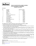
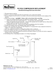
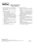
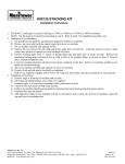
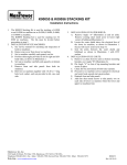
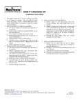
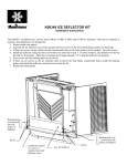
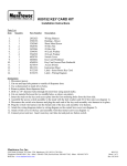
C, E, & H-0200 COMPRESSOR REPLACEMENT ASSEMBLIES
Installation Instructions
Item
1
2
3
4
5
6
7
8
9
10
Qty.
1
1
1
2
6
1
1
2
2
1
Description
Compressor Adapter Plate
Component Mounting Bracket
#10-24 x 1/2 Thread Cutting Screw
#8 Flat Head Sheet Metal Screw
Lead Wires
Installation Instructions
Wire Shield
#10-24 Hex Nuts
#10 Lockwashers
Extruded Tape 7 1/4” Long
P/N
6635214
6264614
5202093
5025553
2075623, 2075633, 2075643, 2075653, 2075663, 2075673
8002233
6278414
5429291
5573163
9202483
ON C, E, & H-0200 SERIES ICE MACHINES
To replace a Tecumseh compressor with a B/M number of AK159AT-032-H4, AK159ET-032-H4, or AK163JT-032-C4, items 1
through 5 are not required. All components are directly replaceable.
To replace a Tecumseh compressor with a B/M number of AE256AT-681-A4, AE334JT-616-A4, or AE255ET-616-A4, all the items
are required. Follow the instructions below:
1. After the old compressor has been removed, fasten down the compressor adapter plate to the ice machine base. Locate by
using the four weldstuds, lockwashers, and hexnuts from the old compressor mounting.
2. Mount the new start capacitor and start relay to the component mounting bracket, as shown. Mount this component and
bracket assembly on the adapter plate. Locate over the two outside weldstuds, with the components facing out, as shown.
3. Install the new compressor with existing sleeves, grommets, lockwashers, and hexnuts. Note: The compressor should be
located so that the electrical hookup box is facing the inside of the ice machine.
4. New compressor refrigeration ports are not located in the same position as the original compressor refrigeration ports.
Repiping will be required.
5. Using supplied wires, wire the:
compressor protector “3” to toggle switch “17”
start relay “L” to transformer board “19”
start relay “M” to compressor “R”
start capacitor to compressor “S”
start relay “S” to start capacitor
6. Important: Change the numerical marking for the compressor protector on the existing wiring diagram (on front panel label)
to correspond with the new compressor (change the 3 to a 1 and the 1 to a 3).
7. On 50 Hz., 230V machines, remove the crankcase pressure regulator valve (CPR valve).
8. Apply wire shield (see illustration on bottom of page) to existing protruding screws of the ice machine base. Apply tape, as
shown on illustration.
Manitowoc Ice, Inc.
2110 South 26 Street, P.O. Box 1720, Manitowoc, WI 54221-1720 USA
Telephone 920-682-0161, Fax - Sales: 920-683-7589, Service/Parts: 920-683-7585, Other: 920-683-7879
Web Site - www.manitowocice.com
8002233
Rev. 03/30/99