1
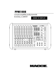
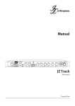
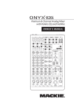
PPM1008 OUTPUT POWER: @ 4 OHMS, 800 WATTS PEAK PER CH MINIMUM LOAD: 4 OHMS PER CHANNEL 8-Channel, 2 x 800 W Professional Powered Mixer OWNER’S MANUAL 2 X 800W PROFESSIONAL POWERED MIXER / FX FOOT SWITCH PPM1008 Important Safety Instructions 1. 2. 3. 4. 5. 6. 7. Read these instructions. Keep these instructions. Heed all warnings. Follow all instructions. Do not use this apparatus near water. Clean only with a dry cloth. Do not block any ventilation openings. Install in accordance with the manufacturer’s instructions. 8. Do not install near any heat sources such as radiators, heat registers, stoves, or other apparatus (including amplifiers) that produce heat. 9. Do not defeat the safety purpose of the polarized or grounding-type plug. A polarized plug has two blades with one wider than the other. A grounding-type plug has two blades and a third grounding prong. The wide blade or the third prong are provided for your safety. If the provided plug does not fit into your outlet, consult an electrician for replacement of the obsolete outlet. 10. Protect the power cord from being walked on or pinched particularly at plugs, convenience receptacles, and the point where they exit from the apparatus. 11. Only use attachments/accessories specified by the manufacturer. CART 12. Use only with a cart, stand, tripod, bracket, or table PORTABLE WARNING specified by the manufacturer, or sold with the apparatus. When a cart is used, use caution when moving the cart/apparatus combination to avoid injury from tip-over. 13. Unplug this apparatus during lightning storms or when unused for long periods of time. 14. Refer all servicing to qualified service personnel. Servicing is required when the apparatus has been damaged in any way, such as powersupply cord or plug is damaged, liquid has been spilled or objects have fallen into the apparatus, the apparatus has been exposed to rain or moisture, does not operate normally, or has been dropped. 15. Do not overload wall outlets and extension cords as this can result in a risk of fire or electric shock. 16. This apparatus shall not be exposed to dripping or splashing, and no object filled with liquids, such as vases or beer glasses, shall be placed on the apparatus. 17. This apparatus has been designed with Class-I construction and must be connected to a mains socket outlet with a protective earthing connection (the third grounding prong). 18. This apparatus has been equipped with an all-pole, rocker-style AC mains power switch. This switch is located on the rear panel and should remain readily accessible to the user. CAUTION AVIS RISK OF ELECTRIC SHOCK. DO NOT OPEN RISQUE DE CHOC ELECTRIQUE. NE PAS OUVRIR CAUTION: TO REDUCE THE RISK OF ELECTRIC SHOCK DO NOT REMOVE COVER (OR BACK) NO USER-SERVICEABLE PARTS INSIDE. REFER SERVICING TO QUALIFIED PERSONNEL ATTENTION: POUR EVITER LES RISQUES DE CHOC ELECTRIQUE, NE PAS ENLEVER LE COUVERCLE. AUCUN ENTRETIEN DE PIECES INTERIEURES PAR L'USAGER. CONFIER L'ENTRETIEN AU PERSONNEL QUALIFIE. AVIS: POUR EVITER LES RISQUES D'INCENDIE OU D'ELECTROCUTION, N'EXPOSEZ PAS CET ARTICLE A LA PLUIE OU A L'HUMIDITE The lightning flash with arrowhead symbol within an equilateral triangle is intended to alert the user to the presence of uninsulated "dangerous voltage" within the product's enclosure, that may be of sufficient magnitude to constitute a risk of electric shock to persons. Le symbole éclair avec point de flèche à l'intérieur d'un triangle équilatéral est utilisé pour alerter l'utilisateur de la présence à l'intérieur du coffret de "voltage dangereux" non isolé d'ampleur suffisante pour constituer un risque d'éléctrocution. The exclamation point within an equilateral triangle is intended to alert the user of the presence of important operating and maintenance (servicing) instructions in the literature accompanying the appliance. Le point d'exclamation à l'intérieur d'un triangle équilatéral est employé pour alerter les utilisateurs de la présence d'instructions importantes pour le fonctionnement et l'entretien (service) dans le livret d'instruction accompagnant l'appareil. 2 PPM1008 19.NOTE: This equipment has been tested and found to comply with the limits for a Class B digital device, pursuant to part 15 of the FCC Rules. These limits are designed to provide reasonable protection against harmful interference in a residential installation. This equipment generates, uses, and can radiate radio frequency energy and, if not installed and used in accordance with the instructions, may cause harmful interference to radio communications. However, there is no guarantee that interference will not occur in a particular installation. If this equipment does cause harmful interference to radio or television reception, which can be determined by turning the equipment off and on, the user is encouraged to try to correct the interference by one or more of the following measures: • Reorient or relocate the receiving antenna. • Increase the separation between the equipment and the receiver. • Connect the equipment into an outlet on a circuit different from that to which the receiver is connected. • Consult the dealer or an experienced radio/TV technician for help. CAUTION: Changes or modifications to this device not expressly approved by LOUD Technologies Inc. could void the user's authority to operate the equipment under FCC rules. 20. This apparatus does not exceed the Class A/Class B (whichever is applicable) limits for radio noise emissions from digital apparatus as set out in the radio interference regulations of the Canadian Department of Communications. ATTENTION — Le présent appareil numérique n’émet pas de bruits radioélectriques dépassant las limites applicables aux appareils numériques de class A/de class B (selon le cas) prescrites dans le réglement sur le brouillage radioélectrique édicté par les ministere des communications du Canada. 21. Exposure to extremely high noise levels may cause permanent hearing loss. Individuals vary considerably in susceptibility to noise-induced hearing loss, but nearly everyone will lose some hearing if exposed to sufficiently intense noise for a period of time. The U.S. Government’s Occupational Safety and Health Administration (OSHA) has specified the permissible noise level exposures shown in the following chart. According to OSHA, any exposure in excess of these permissible limits could result in some hearing loss. To ensure against potentially dangerous exposure to high sound pressure levels, it is recommended that all persons exposed to equipment capable of producing high sound pressure levels use hearing protectors while the equipment is in operation. Ear plugs or protectors in the ear canals or over the ears must be worn when operating the equipment in order to prevent permanent hearing loss if exposure is in excess of the limits set forth here. Duration, per day in hours 8 6 4 3 2 1.5 1 Sound Level dBA, Slow Response 90 92 95 97 100 102 105 0.5 110 0.25 or less 115 Typical Example Duo in small club Subway Train Very loud classical music Greg and Ben screaming at Troy about deadlines Loudest parts at a rock concert WARNING — To reduce the risk of fire or electric shock, do not expose this apparatus to rain or moisture. We realize that you must be keen to try out your new powered mixer, but please read the safety instructions on page 2, and this page first. Ready, steady, go! 1. Turn the channel level, mon 1, and FX/mon 2 controls fully down. 2. Turn down the compressor controls (ch. 1–4). 3. Set all the EQ controls to the center, including the graphic EQ sliders. Setup 4. Turn down the main level and monitor 1 level controls. The PPM1008 powered mixer is designed to be easy to operate, and to be set up quickly. 5. For each channel, press the gain switch in (low gain) if you are using a line-level source. Press it out (high gain) if you are using a microphone or other low-level source. Place the powered mixer in a position where it is easy to reach the controls. All the controls and input connection points are located on the front panel so you can make quick adjustments and connections on stage. Make sure there is at least 6 inches of airspace behind the powered mixer for ventilation. There are two fans inside the cabinet to cool the power amplifier section. Use the powered mixers in a nice clean and dry environment, free from dryer lint and dust bunnies. Connections 1. Be sure the rear-panel power switch is off before making any connections. 2. Push the linecord securely into the IEC connector on the rear panel, and plug it into a 3-prong AC outlet that is properly configured for the voltage of your powered mixer. 3. Plug a balanced microphone into one of the mic XLR (3-pin) connectors on the front panel. Or you can connect any line-level signal (keyboard, or guitar preamp) to a line-level input using a TS or a TRS 1/4" plug. 4. You can connect a guitar directly to inputs 5 or 6 without need for a DI box, if you press the hi-z switch on these channels. 5. The insert jacks can be used to connect an external effects or dynamics processor into the signal chain. See page 13 for more details. 6. Plug the speakers (4 ohms or greater) into the speaker output jacks on the rear panel. If you plug two speakers in one side, each speaker must be 8 ohms or greater to maintain a 4-ohm minimum load on the amplifier. Use at least 18 gauge speaker cable with 1/4" TS plugs or Speakon® plugs. For now, set the rear panel power amp mode switch to stereo mains. Don’t use guitar cords for speaker cables! They’re not designed to handle speaker-level signals and could overheat. Part No. SW0685 Rev. D ©2009 LOUD Technologies Inc. All Rights Reserved. Episode 3: The Mackie marketing department landing party arrives on Aldebaran 3 to investigate a distress signal, with hilarious results. Owner’s Manual Read This Page! 6. For condenser mics, push in the phantom power switch. If you are using both condenser and dynamic mics, don’t worry. Phantom power will not hurt most dynamic mics. Check the microphone’s user manual if you’re not sure. 7. Play something into an input at real-world levels, and turn up the channel level to U (unity). 8. In normal playing, the channel's OL LED should only light occasionally. If it stays on for a large portion of your performance, check that the gain switch is set correctly. 9. Slowly turn up the main level control until you hear the signal in your speakers. 10. Repeat steps 5 to 8 for the remaining channels. 11. If needed, apply some EQ wisely. 12. Adjust the levels to get the best mix. Keep the level controls fully down on unused channels. Other Notes • Only connect the powered mixer's speaker-level outputs to passive loudspeakers. • When shutting down, turn off any external amplifiers or powered loudspeakers first. When powering up, turn on any external amplifiers or powered loudspeakers last. • Save the shipping box! Please write your serial number here for future reference (i.e., insurance claims, tech support, return authorization, make dad proud, etc.) Purchased at: Date of purchase: Owner’s Manual 3 PPM1008 Introduction It is possible that only one person will read this manual all the way through. Hello mom. Here's another manual from your boy. • Tape/CD stereo RCA outputs Thank you for choosing a Mackie professional powered mixer. These powerful mixers are designed to meet the needs of almost any small to medium-sized club, meeting room, sanctuary, or outdoor gathering. • 12-segment stereo output meters on main mix, and mono meter on monitor 1 At Mackie, we know what it takes to be roadworthy. After all, our mixers have traveled all over the world under the worst of conditions and the best of conditions, and we’ve applied what we’ve learned to the mechanical design of our powered mixers. • Precision passive switch for enhanced clarity and LF response with key Mackie passive speakers Reliability is paramount to sound reinforcement. That’s why our engineers have subjected our powered mixers to the most rigorous and fiendish tests imaginable to fine-tune the design and extend its limits beyond those of ordinary mixers or amplifiers. Features • Two internal power amplifiers each rated at 800 watts peak at 4 ohms • Three selectable amplifier modes (stereo main, mono-main/monitor 1, or mon 1/mon 2) • 8 channels (6 mono, 2 stereo) • Mic inputs on all channels • Line-level inputs (6 mono, 2 stereo) • RCA inputs on stereo channels • Insert jacks on mono channels • Channels 5 and 6 allow direct connection of guitars and basses without a DI box • 3-band EQ with sweepable mid-range frequency on mono channels • 4-band EQ on stereo channels • Monitor 1 send • Main mix stereo line outputs • Main mix mono sub out • Amplifier line-level inputs allow the connection of external mixers if more channels are needed • Footswitch connection for FX mute/unmute • Break switch mutes all mono channels • Speakon and 1/4" power amp outputs • Polycarbonate sides with built-in metal handles • Modern and splendidly-stylish powered rabbit hutch design How To Use This Manual The first pages after the table of contents are the hookup diagrams. These show typical setups for fun times with your powered mixer. Next is a detailed tour of the entire mixer. The descriptions are divided into sections, just as your mixer is organized into distinct zones: • Rear panel: The AC input, power switch, speaker-level outputs and amplifier mode switch • Patchbay: The lower front section, where you connect microphones and guitars etc. • Channel Strips: The channel strips where you adjust and control each channel • Master Section: The section on the right, with graphic EQs and main level controls • Stereo Effects Processor Throughout these sections you’ll find illustrations with each feature numbered and described in nearby paragraphs. This icon marks information that is critically important or unique to the mixer. For your own good, read them and remember them. This icon will lead you to some explanations of features and practical tips. Go ahead and skip these if you need to leave the room in a hurry. • FX/monitor 2 send (selectable pre/post) Appendix A: Service information. • +48v Phantom power can be applied to all mics Appendix B: Connectors. • Built-in compressors on the first 4 mono inputs (dedicated in-line compression) Appendix C: Technical information. • 24 built-in Running Man 32-bit effects with input gain, tap delay, and footswitch mute/unmute 4 • Independent 9-band graphic EQs with constantQ filters on main and monitor outputs PPM1008 Appendix D: Table of Effects Presets The thickness of the manual makes it ideal for fitting under wobbly table legs. Mackie's technical writers also wear them on their heads, as they make an excellent shield from Venusian mind-probes. IMPORTANT SAFETY INSTRUCTIONS......................... 2 READ THIS PAGE!..................................................... 3 INTRODUCTION....................................................... 4 HOOKUP DIAGRAMS............................................... 6 REAR PANEL FEATURES.......................................... 10 1. POWER CONNECTION.............................. 10 2. POWER SWITCH...................................... 10 3. SPEAKER-LEVEL OUTPUTS........................ 10 4. POWER AMP MODE SWITCH................... 11 5. VENTILATION AND REAR PANEL............... 11 6. HANDLES................................................ 11 FRONT PANEL FEATURES........................................ 12 PATCHBAY 7. MIC INPUTS............................................ 12 8. MONO LINE INPUTS (CH. 1 TO 4)............. 13 9. LINE/INSTRUMENT INPUTS (CH. 5, 6)...... 13 10. STEREO LINE INPUTS (CH. 7 AND 8)......... 13 11. RCA INPUTS (CH. 7 AND 8)..................... 13 12. INSERT (CH. 1 TO 6)................................ 13 13. TAPE OUTPUTS ...................................... 13 14. BREAK SWITCH AND LED ........................ 13 15. FX/MON 2 SEND OUTPUT ...................... 14 16. FX FOOTSWITCH..................................... 15 17. MON 1 SEND ......................................... 15 18. MAIN SUB.............................................. 15 19. MAIN OUTPUTS ..................................... 15 20. POWER AMP INPUTS ............................. 15 CHANNEL CONTROLS 21. MON 1................................................... 17 22. FX/MON 2............................................. 17 23. HIGH EQ................................................. 17 24. MID EQ LEVEL (CH. 1 TO 6)...................... 17 25. MID EQ FREQUENCY (CH. 1 TO 6)............ 17 26. HIGH MID EQ LEVEL (CH. 7 AND 8).......... 17 27. LOW MID EQ LEVEL (CH. 7 AND 8)........... 17 28. ICE CREAM DISPENSER............................ 17 29. LOW EQ.................................................. 18 30. OVERLOAD (OL) LED................................ 18 31. CHANNEL LEVEL...................................... 18 32. GAIN SWITCH......................................... 18 33. COMPRESSOR......................................... 19 34. HI-Z SWITCH.......................................... 19 35. POWER LED............................................ 20 MASTER CONTROLS 36. MAIN MASTER GRAPHIC EQ.................... 20 37. FX TO MAIN............................................ 20 38. MAIN LEVEL............................................ 20 39. 100 HZ RUMBLE REDUCTION SWITCH...... 21 40. MAIN MIX METERS................................. 21 41. MONITOR 1 MASTER GRAPHIC EQ........... 21 42. FX TO MON 1......................................... 21 43. MONITOR 1 LEVEL.................................. 21 44. 100 HZ RUMBLE REDUCTION SWITCH...... 21 45. MONITOR 1 METER................................. 21 46. PHANTOM SWITCH................................. 22 47. PRECISION PASSIVE EQ........................... 22 48. POWER AMP LIMITER LEDS...................... 22 STEREO EFFECTS PROCESSOR 49. FX/MON 2 SEND MASTER....................... 22 50. SIG/OL LED............................................ 22 51. FX SEND (POST)/MON 2 SEND (PRE)....... 23 52. PRESET DISPLAY..................................... 23 53. PRESET SELECTOR, TAP DELAY AND LED.... 23 54. INTERNAL FX MUTE................................. 23 APPENDIX A: SERVICE INFORMATION..................... 24 APPENDIX B: CONNECTIONS.................................. 25 APPENDIX C: TECHNICAL INFORMATION................. 27 APPENDIX D: TABLE OF EFFECTS PRESETS................ 30 PPM1008 LIMITED WARRANTY.............................. 31 Owner’s Manual Contents Need help with your new mixer? • Visit www.mackie.com and click Support to find: FAQs, manuals, addendums, and documentation. • Email us at: [email protected]. • Telephone 1-800-898-3211 to speak with one of our splendid technical support chaps (Monday through Friday, normal business hours, PST). Owner’s Manual 5 PPM1008 Hookup Diagrams Front Panel Power Amp Mode switch set to Stereo Mains Rear Panel Microphones press HI-Z button press HI-Z button Adjust Vocal Compression Keyboards Portable Recorder SRM450 v2 Powered Stage Monitors (plays mon 1 output) Powered Subwoofers (plays main mix below 100 Hz) Passive Speakers (plays stereo main mix) This diagram shows microphones attached to channels 1 and 2, electric guitars connected directly to channels 5 and 6 (with hi-z switch pressed in), and a keyboard attached to channel 7's stereo inputs. A portable recorder is attached to the stereo tape outputs to record the performance. Mackie SRM450v2 powered monitors are connected to the monitor 1 send, and play as stage monitors. The mon 1 controls of each channel allow you to set up a stage monitor mix that is independent of the main mix. Passive speakers are connected to the speaker-level power output of the powered mixer, and they play the main stereo mix to your audience. Powered subwoofers are connected to the main mix sub out, to reinforce the low end in your system. Club System 6 PPM1008 Acoustic Guitar and Mic Front Panel Power Amp Mode switch set to Mains/Mon 1 Rear Panel press HI-Z button Adjust Vocal Compression Owner’s Manual Microphones Drum Machine Power Amplifier dual-mono mode C300z Passive Stage Monitors (plays mon 1 output) Keyboards SRM150 Powered Monitor (plays mon 1 output) Passive Subwoofers (plays main mix below 100 Hz) Passive Speakers House System (plays mono main mix) This diagram shows microphones attached to the mic inputs of channels 1 to 4, an electric guitar connected directly to channel 5 (with hi-z switch pressed in), an acoustic guitar mic connected to channel 6 mic in, a keyboard attached to channel 7's stereo inputs, and a drum machine to channel 8. A Mackie SRM150 powered monitor is connected to the monitor 1 send, and acts as a personal stage monitor to the keyboard player. The mon 1 knobs of each channel allow you to set up a monitor mix that is independent of the main mix. The power amp mode switch is set to play the mono main mix on ch. A, and monitor 1 mix on ch. B. Passive speakers are connected to the channel A speaker-level power output of the powered mixer, and they play the main mono mix to your audience. Passive subwoofers are powered by an amplifier connected to the main mix sub out, to reinforce the low end in your main mix. C300z passive stage monitors are connected to the channel B speaker-level power output of the powered mixer. These play the stage monitor mix 1 to your performers. House of Worship System Owner’s Manual 7 PPM1008 Wireless Microphone Microphones Front Panel Power Amp Mode switch set to Stereo Mains Rear Panel Graphic EQ iPodTM Docking Station Wireless Mic Receiver Mackie d.2 Pro DJ Production Console BOOTH MAIN OUT L R LINE MIC LIVE RECORD ~100-240 VAC 50-60Hz 20W L L FX SEND L R L(MONO) PGM 1 PGM 2 R PHONO L CD R RETURN PHONO L L R R CD HD1521 Powered Speaker HD1521 Powered Speaker MIC L R R LINE PHONO GND LINE PHONO GND R Turntables with phono-level output Powered Subwoofer (right main mix) Passive Speakers Powered Subwoofer (plays stereo main mix) (left main mix) This diagram shows a wireless microphone receiver connected to the channel 1 line input, a graphic EQ connected to channel 1's insert jack (to help control feedback in the wireless mic), a microphone connected to channel 2, and an iPod docking station attached to channel 8's RCA inputs. A Mackie d.2 Pro DJ production console is connected to two turntables, and its RCA output connects to the powered mixer's channel 7 stereo RCA inputs. Use the d.2 Pro's advanced DJ controls to get the best performance from your records. Use the powered mixer to play the d.2 Pro output, and control the mics and iPod. The power amp mode switch is set to play the stereo main mix in the passive speakers, connected to the speaker-level power outputs. Mackie HD1521 powered speakers and powered subwoofers are connected to the line-level main mix outputs, and also play the stereo main mix to your audience. DJ System 8 PPM1008 Front Panel Power Amp Mode switch set to Mon 1/Mon 2 Rear Panel press HI-Z buttons Adjust Vocal Compression Owner’s Manual Microphones Send Guitar Processor Return (connected to INSERT) HD1531 Powered Speaker HD1531 Powered Speaker C200z Passive Stage Monitors (plays mon 2 output) Keyboards C300z Passive Stage Monitors (plays mon 1 output) Electronic Drum Kit Powered Subwoofer (plays right main mix) Powered Subwoofer (plays left main mix) This diagram shows microphones attached to the mic inputs of channels 1 to 4, electric guitars connected directly to ch. 5 and 6 (with hi-z switches pressed in), a guitar processor connected to ch.6 insert, a keyboard attached to channel 7's stereo inputs, and an electronic drum kit attached to channel 8. Add vocal compression as required, by tweaking the compression knobs on channels 1 to 4. The power amp mode switch is set to play the monitor 1 mix on channel A, and monitor 2 mix on channel B. Note: Press in the front panel FX send/mon 2 send switch, or monitor 2 will not play. Mackie HD1531 powered speakers and powered subwoofers are connected to the line-level main mix outputs, and play the stereo main mix to your audience. C200z passive stage monitors are connected to the channel B speaker-level power output of the powered mixer. These play the stage monitor mix 2 to your performers. C300z passive stage monitors are connected to the channel A speaker-level power output, and play stage monitor mix 1. Large Band System Owner’s Manual 9 PPM1008 Rear Panel Features 2 X 800W PROFESSIONAL POWERED MIXER 6 4 2 3 1 6 OUTPUT POWER: @ 4 OHMS, 800 WATTS PEAK PER CH MINIMUM LOAD: 4 OHMS PER CHANNEL 5 1. POWER CONNECTION 3. SPEAKER-LEVEL OUTPUTS This jack accepts the supplied 3-prong IEC AC power cord. These output connections provide speaker-level output power from the internal power amplifiers to your passive speakers. The power output of the PPM1008 is 500 watts rms per channel into 4 ohms. Before you plug the AC power cord into the powered mixer, make sure that the voltage of your unit is the same voltage as your local AC mains supply. Use only the power cord supplied. Also, disconnecting the plug’s ground pin is dangerous. Please don’t do it. 2. POWER SWITCH Press the top of this rocker switch inwards to turn on the mixer. The front panel power LED [35] will glow with happiness, or at least it will if you have the mixer plugged into a suitable live AC mains supply. Press the bottom of this switch to turn off the mixer, whenever you feel that this would be a safe thing to do. Half-way through a heavy metal guitar solo might not be such a good time. As a general guide, you should turn on your mixer first, before any external power amplifiers or powered speakers, and turn it off last. This will reduce the possibilities of any turnon, or turn-off thumps in your speakers. 10 PPM1008 2 X 800W PROFESSIONAL POWERED MIXER Only passive loudspeakers should be connected to these speaker-level outputs. The outputs can be selected with the amp mode switch [4] to be either the stereo main mix, mono main mix/monitor 1, or monitor 1/monitor 2. Two common types of connector are provided for your convenience: Speakons and 1/4" TS. / 1– 1+ FX FOOT SWITCH COLD HOT 1– 1+ 2+ 2– • Speakon outputs are wired Pin 1+ positive (hot) and Pin 1– negative (cold). Mono Speakon Connection SLEEVE SLEEVE TIP TIP TIP SLEEVE 1/4" TS Connection These two types of outputs are wired in parallel, and it is possible to use both types at once. 5. VENTILATION and REAR PANEL Ventilation holes in the rear panel and the bottom panel allow the internal fans to flow breezy and mintyfresh cooling air over the internal power amplifiers. Do not obstruct these holes, or the amplifiers may overheat and shut down. Do not remove the feet, as these keep the powered mixer off the ground for ventilation. Do not place the powered mixer on a carpeted or similar soft and fuzzy surface that may obstruct the ventilation holes in the bottom panel. The minimum impedance that the 2 Xpowered 800W PROFESSIONAL POWERED MIXER mixers can handle is 4 ohms per channel, and 6. HANDLES we recommend that you do not go below this. If you are using both outputs per channel, make sure These metal handles are delightfully modern in each loudspeaker is 8 ohms impedance or greater. styling and good looks, and truly represent the perfect accessory to accent your busy work schedule. Use the 4. POWER AMP MODE SWITCH handles to carefully lift and move the powered mixer. Better yet, have someone else lift it for you. They will This three-position switch lets be remarkably pleased with its light weight, and high you choose which signal paths power, ideal for all sorts of road trips. from the mixer section are sent Owner’s Manual • 1/4" TS outputs are wired Tip positive, and Sleeve negative. to the internal power amplifiers. This allows considerable flexibility in the use of the powered mixer. For example, if you already have powered main loudspeakers, you could use the PPM1008 power amplifiers to run passive stage monitors. Stereo Mains The output from channel A is the left side of the main mix, and the output from channel B is the right side of the main mix. Choose this position to play a straight stereo show. Mains/Monitor 1 Channel A is the mono main mix, and channel B is the OUTPUT POWER: @ 4 OHMS, 800 WATTS PEAK PER CH 4 OHMS PER CHANNEL monitor 1 mix. In this setup, youMINIMUM couldLOAD: run a mono PA system on one channel, and a passive stage monitor system on the other. Monitor 1/Monitor 2 Channel A is the monitor 1 mix, and channel B is the monitor 2 mix. In this setup, the internal power amplifiers are powering two independent passive stage monitor systems. Make sure that the front panel FX send/mon 2 send switch [51] is pressed in (mon 2) , or there will be no monitor 2 signal to the internal power amplifier channel B. If anything is plugged into the front panel power amp inputs [20], then this switch has no effect. The internal power amplifier will play whatever signals are coming into the power amp inputs. Owner’s Manual 11 PPM1008 Front Panel Features 2 X 800W PROFESSIONAL POWERED MIXER / 11 12 8 9 10 14 FX 13 7 Patchbay section This is where you plug in things such as: microphones, line-level instruments, guitars, and effects, a recorder, PA system, powered monitors, powered subwoofer etc. (The speaker-level outputs from the internal power amplifiers are on the rear panel.) Check out the hookup diagrams for some connection ideas. See Appendix B (page 25) for further details and some rather lovely drawings of the connectors you can use with your mixer. FOOT SWITCH 7. MIC INPUTS We use phantom-powered, balanced microphone inputs just like the big studio mega-consoles, for e xactly the same reason: This kind of circuit isexcellent at rejecting hum and noise. You can plug in almost any kind of mic that has a standard XLR-type male mic connector. Professional ribbon, dynamic, and condenser mics all sound excellent through these inputs. The mic inputs will handle any kind of mic level you can toss at them, without overloading. Microphone-level signals are passed through the mixer's splendid microphone preamplifiers to become line-level signals. Because more gain is required to boost the microphone level signals, make sure the gain switch [32] is in the up position when you are using microphones. Channels 1 to 4 have the extra benefit of built-in signal in-line compressors [33]. These can be adjusted to add just the right amount of compression to your vocals and help prevent distortion and the effects of tonsillitis. 12 PPM1008 12. INSERT (CH. 1 to 6) Most modern professional condenser mics are equipped for phantom power, which lets the mixer send low-current DC voltage to the mic’s electronics through the same wires that carry audio. (Semi-pro condenser mics often have batteries to accomplish the same thing.) “Phantom” owes its name to an ability to be “unseen” by dynamic mics (Shure SM57/SM58, for instance), which don’t need external power and aren’t affected by it anyway. These unbalanced 1/4" jacks on channels 1 to 6 are for connecting serial effects processors such as compressors, equalizers, de-essers, or filters. The insert point is after the gain switch [32] and compressor circuits (on channels 1 – 4), but before the channel’s EQ and level [31] controls. The channel signal can go out of the insert jack to an external device, be processed (or whatever) and come back in on the same insert jack. To do this requires a special insert cable that must be wired thusly: The mixer's phantom power is globally controlled by the phantom [46] switch on the front panel. (The phantom power for all channels is turned on and off together.) Never plug single-ended (unbalanced) micro phones, or ribbon mics into the mic input jacks if phantom power is on. Do not plug instrument outputs into the mic XLR input jacks with phantom power on, unless you know for certain it is safe to do so. 8. MONO LINE INPUTS (CH. 1 to 4) These 1/4" jacks share circuitry (but not phantom power) with the mic preamps, and can be driven by balanced or unbalanced sources. To connect balanced lines to