Transcript
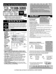
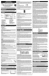
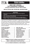
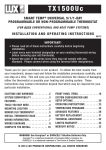
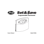
Complete, Easy To Read
INSTALLATION AND OPERATING
INSTRUCTIONS
4. Hold the base against the wall. Route the wires through the hole below
the terminal block. Position the base for best appearance (to hide any marks
from an old thermostat). Attach the base to the wall with the two screws
provided.
CONNECTING THE WIRES
5. Wires must be trapped between black clamp and brass
terminal.
6. Securely tighten all 7 electrical terminal screws.
CAG1500 SERIES
SMART TEMP ELECTRONIC THERMOSTAT
PM
SET
SUNDAY
HEAT
OFF
WEEKDAY
PROGRAM
COOL
SET
DAY/TIME
Installs Easily
Set Day and Time
Easy as
1–2–3
These diagrams are provided for new installations or unreferenced wires.
HEATING SYSTEMS
COOLING SYSTEMS
JUMPER
PROVIDED
G
Y
JUMPER
PROVIDED
W RH RC
B
O
G
Y
W RH RC
B
O
Choose Heat or Cool
LUX PRODUCTS CORPORATION
Mt. Laurel, New Jersey 08054, USA
43371
G
W
F
H
4
RH
RC
R
V
5
WARNING: Use Energizer® or DURACELL® Alkaline Batteries Only.
Energizer® is a registered trademark of Eveready Battery Company, Inc.
DURACELL® is a registered trademark of The Gillette Company, Inc.
I M P O R TA N T !
Please read all instructions carefully before beginning
installation. Save them for future reference. Before removing
any wiring from your existing thermostat, its wires must be
labeled with their terminal designations. Ignore the color of the
wires since they may not comply with any standard.
Thank you for your confidence in our product. To obtain the best
results from your investment, please read these instructions and acquaint
yourself with your purchase before installing your new thermostat. Then
follow the installation procedures, one step at a time. This will save you
time and minimize the chance of damaging the thermostat and the
systems it controls. These instructions may contain information beyond
that required for your particular installation. Please save for future
reference.
COMPATIBILITY
FEATURES
Y
RC
R
F
C*
6
V
N O T E
The FAN switch works only if your system provides a wire for the
CAG1500’s “G” terminal.
HEATING / COOLING SYSTEMS
HEATING / COOLING SYSTEMS
4- or 5-WIRE WITH ONE TRANSFORMER
5- or 6-WIRE WITH TWO TRANSFORMERS
JUMPER
PROVIDED
G
Y
G
JUMPER
REMOVED
W RH RC
Y
C*
6
W
B
RH
RC
R
V
5
H
4
O
B*
G
O
Y
W RH RC
G
Y
F
C*
6
W
B
RH RC
R
H
4
B*
Open the door on the front of the thermostat. Rotate the dial to the
SET DAY/TIME position. You should see the display pictured below with a
day of the week flashing.
● Press UP to change day
Su
of week.
● Press NEXT to set the time;
it will flash.
AM
● Press UP or DOWN to
change time of day.
12:00
O
O
V
5
When you are finished setting the day and time, rotate the dial to RUN to
return to normal operation or to another position to continue programming.
HARDWARE RESET
This button will unlock your thermostat and read option switch positions,
before the unit begins normal operation. It is located inside on the rear of the
unit’s circuit board. It is a small square component labeled S8, with a white
button at it’s center.
SOFTWARE RESET
All COMMON WIRES MUST BE TAPED OFF.
If "Y" and "C" are both present, "C" is a common wire. DO NOT USE "C"! TAPE IT OFF!
*If a "B" wire in your system is a system common, then
connecting it at the "B"
terminal may cause damage to your system. TAPE IT OFF!
SETTING THE AIR FILTER LIFE
This value sets the number of days to be counted before a filter
change is indicated.
To set the AIR FILTER USAGE LIMIT:
1. Rotate dial to AIR FILTER.
2. LCD shows: SET LIMIT at lower left, with current setting at center
screen.
3. With a new filter installed, use the UP/DOWN keys to change this
value to the number of days of useful filter life specified by your filter
manufacturer. The available settings are: 000, 30, 60, 90, and 120 days.
The default air filter life setting is 90 days. A selection of 000 days will
disable the Air Filter Counter feature completely, and hide both the
“number of days” and the “bar graph” items from the red lower portion of
the display.
4. The counter for the Air Filter Usage Monitor is automatically reset
back to zero when the usage limit setting value has been changed.
5. Return the dial to the RUN position when finished.
RESETTING AIR FILTER COUNTER
To reset the air filter counter when you replace your filter:
1. Rotate dial to AIR FILTER.
2. Press and release COPY to reset counter
3. Press and release COPY again to restore previous count.
4. Return the dial to the RUN position when finished.
TEMPERATURE OVERRIDE
SETTING THE TIME AND DAY:
F
The CAG1500 can be used with most single stage 24 volt gas, oil or
electric heating and air conditioning systems, single stage heat pumps, or
gas millivolt heating systems. It cannot be used with 3 wire zone valves,
120 volt heating systems, or multi stage heat pumps. Ask your dealer for
other LUX thermostats to control those systems.
G
TEMPERATURE ADJUSTMENT:
Pressing an arrow key once adjusts the set temperature by one degree in
the associated direction. Holding the key will automatically advance the
setting in the associated direction.
CHANGING OTHER SETTINGS:
If there are many choices for a value, usually that setting will automatically
advance by holding one of the arrow keys. Some settings though, must be
changed one press at a time.
DISPLAY ILLUMINATION:
Press the light bulb button to illuminate the display. Pressing other
buttons will keep the display illuminated until no button has been pressed for
approximately 20 seconds.
FAN MODES:
The fan switch has three positions AUTO, CLEAN, and ON. Setting the
FAN switch to AUTO automatically runs your system's fan as required only
for heating and cooling. The CLEAN position insures that your system's fan
runs at least the programmed minimum duty cycle. The default duty cycle
requires it to run 15 minutes every hour. Setting the FAN switch to ON runs
your system's fan continuously. The FAN icon will flash whenever the fan is
running.
Use this front panel RESET to return all software settings and programs to
their default values. Option jumpers will be read and operation will
correspond to their current positions. SOFTWARE RESET is disabled while
your thermostat is locked. To assist in reprogramming, copy your programs
into the chart provided before using SOFTWARE RESET.
OVERRIDE allows you to change the current SET TEMPERATURE in
HEAT or COOL until the next program period without changing your
temperature control programs.
● Press UP/DOWN to change the current temperature setting. The
OVERRIDE indicator appears on display.
● The OVERRIDE will be canceled at the start of the next program period,
and the temperature setting will return to its programmed value.
● An OVERRIDE may be terminated by rotating the dial, switching the
mode to OFF, or initiating a HOLD.
● Adjusting the set temperature to its program value will also cancel an
OVERRIDE.
TEMPERATURE HOLD
HOLD may be used for manual temperature control. HOLD is the
simplest means to set and maintain a fixed temperature. It allows you to
set and maintain a fixed temperature indefinitely in Heat or Cool without
concern for programming. To initiate a HOLD:
● Press and release HOLD.
● Adjust temperature as desired with UP/DOWN.
● Temperature setting will not change until the HOLD is cancelled.
● To cancel a HOLD, press and release HOLD again, rotate the dial, or
switch mode to OFF.
ADVANCED FEATURES
TEMPERATURE SWING
LARGE
BACKLIT
DISPLAY
G
LIGHT
Y
W
RH
RC
B
IAQ
INDEPENDENTLY
PROGRAMMABLE
FAN
EASY
PROGRAMMING
WITH
LUX SPEED DIAL®
The CAG1500 provides four independent programming periods per day for
HEAT, COOL, and FAN. Each is programmed separately. You can use the
default programs or alter them to suit your schedule.
A thermostat works by turning your heating or cooling system on or off
whenever the room temperature varies from the set-point temperature.
This variation is the "swing." Your system should cycle on about 3 to 6
times per hour. A smaller swing number increases the number of cycles,
so room temperature is more constant. A larger swing number decreases
the number of cycles, but saves energy in most cases.
DEFAULT ENERGY STAR® TEMPERATURE PROGRAM
SWING SETTING
As supplied from the factory, the following ENERGY STAR® approved
program will be used for temperature control in RUN mode. This program
and all other software settings may be restored to their default values via a
SOFTWARE RESET.
1.
2.
3.
4.
5.
PROGRAMMING
2 WIRE SYSTEM HEAT ONLY
UP
DOWN
O
JUMPER
MODE SWITCH
24 VOLT
HEAT
TRANSFORMER
HEAT
120 V CA
PERIOD
HEAT MODE
COOL MODE
Morning 6:00 AM 70°F (21°C) 6:00 AM 78°F (26°C)
8:00 AM 62°F (17°C) 8:00 AM 85°F (29°C)
Day
Evening 6:00 PM 70°F (21°C) 6:00 PM 78°F (26°C)
10:00 PM 62°F (17°C) 10:00 PM 82°F (28°C)
Night
3 WIRE SYSTEM HEAT ONLY
(3rd WIRE FOR FAN)
●
●
●
●
●
●
●
●
●
●
●
Small elegant design
Exclusive LUX Speed Dial®
EL Illuminated Display
Comprehensive Graphical
Filter Monitor
7 Day Programming
Energy Star Compliant
4 Periods Per Day
Independent Fan Program
Programmable (minimum)
Fan Duty Cycle
Nonvolatile Memory For
All Programs And Settings
Temporary Temperature
Override
●
●
●
●
●
●
●
Temperature Hold
Keyboard Lockout
F/C Temperature Display
12/24 Hr Clock Display
Adjustable Temperature
Differential / Cycle Rate
User Temperature Offset /
Calibration
5/2 minute selectable
minimum Run/Off time provides
short cycle and compressor
protection
G
Y
W
RH
RC
FAN
WEEKDAY PROGRAMMING
120 VAC
3 WIRE SYSTEM COOL ONLY
Y
W
RH
RC
B
24 VOLT
COOLING
TRANSFORMER
A/C
COMPRESSOR
INSTALLATION
120 VAC
Please read all instructions carefully before beginning installation.
C A U T I O N
Turn off electricity to the appliance before installing or
servicing thermostat or any part of the system. Do not
turn electricity back on until work is completed.
● Do not short (jumper) across electric terminals on furnace or air
conditioner to test the system. This may damage the thermostat and
void your warranty.
● All wiring must conform to local codes and ordinances.
● The thermostat should be limited to a maximum of 1.5 amps;
higher current may cause damage to the thermostat.
● Your thermostat is a precision instrument. Please handle it with
care.
●
4 WIRE SYSTEM HEATING AND COOLING
G
Y
W
RH
RC
B
JUMPER
A/C
COMPRESSOR
FAN
24 VOLT
HEAT/COOL
TRANSFORMER
HEAT
Y
W
RH
RC
B
1. Select HEAT or COOL with the
mode switch.
2. Rotate dial to SET WEEKDAY
PROGRAMS. You will see the display
shown here:
PROGRAM MO
MORN
START AT
AM
SET
3. The HEAT or COOL set temperature will be displayed on the right side of
the display. The start time for the displayed period will flash to show that this
may be changed.
4. Use the UP/DOWN arrow keys to change the start time for this period.
One period ends at the start time of the next period. The beginning of that
period may not be any closer to the beginning of the next period than one
15 minute increment.
5. Press NEXT to accept the displayed start time and advance to edit the
SET TEMPERATURE.
6. Use the UP/DOWN arrow keys to change the flashing HEAT or COOL
set temperature to the temperature you desire.
7. Press NEXT to accept the displayed set temperature and advance to
edit the start time for the next period. It will be flashing.
8. Repeat for each of the four periods per day. When all the periods for a
day have been set, the start time for the next morning will be displayed
flashing so that it may be edited.
9. Repeat PROGRAMMING for each remaining day.
10. Rotate the dial back to RUN to accept all current values and end the
programming session.
O
1. To program Saturday or Sunday,
select HEAT or COOL and rotate the
dial to SET WEEKEND PROGRAMS.
You will see a display similar to that
shown here:
2. Use steps 3 - 10 described in
WEEKDAY PROGRAMMING to
program Saturday and Sunday.
PROGRAM
HEAT
6:00 70
AM
On replacement installations, mount the new thermostat in place of the
old one unless the conditions listed below suggest otherwise. On new
installations, follow the guidelines listed below.
1. Locate the thermostat on an inside wall, about 5 ft. (1.5m) above the
floor, and in a room that is used often.
2. Do not install it where there are unusual heating conditions, such as:
in direct sunlight; near a lamp, television, radiator, register, or fireplace;
near hot water pipes in a wall; near a stove on the other side of a wall.
3. Do not locate in unusual cooling conditions, such as: on a wall
separating an unheated room; or in a draft from a stairwell, door, or
window.
4. Do not locate in a damp area. This can lead to corrosion that may
shorten thermostat life.
5. Do not locate where air circulation is poor, such as: in a corner or an
alcove; or behind an open door.
6. Do not install the unit until all construction work and painting has
been completed.
JUMPER
REMOVED
FAN
COOLING
SET
REMOVING THE OLD THERMOSTAT
1. Switch electricity to the furnace and air conditioner
OFF; then proceed with the following steps.
2. Remove cover from old thermostat. Most are snapon types and simply pull off. Some have locking
screws on the side. These must be loosened.
3. Note the letters printed near the terminals. Attach
labels (enclosed) to each wire for identification.
Remove and label wires one at a time. Make sure the wires do not fall
back inside the wall.
4. Loosen all screws on the old thermostat and remove it from the wall.
120 VAC
C A U T I O N
Be careful not to drop the unit or disturb electronic parts.
Leave the door closed while the body is being removed
from the base.
3. Remove the body from the thermostat’s base by pressing the thumb
latch at the bottom center of the unit and swinging the body away.
N O T E
If you are mounting the base to soft material like plasterboard or if you
are using the old mounting holes, the screws may not hold. Drill a 3/16
in. (4.8mm) hole at each screw, and insert the plastic anchors provided.
DAY
120 VAC
THURS
DAY
SINGLE STAGE HEAT PUMP SYSTEM
PERIOD
HEAT
COOL
TIME TEMP. TIME TEMP.
PERIOD
HEAT
COOL
TIME TEMP. TIME TEMP.
G
Y
W
RH
RC
B*
O*
MON
DAY
EVE
SET
FILTER
SETUP OPTIONS
JUMPER SETTINGS
There are four jumpers, each controls a setting depending on its
position.
GAS/ELECTRIC MODE - J4
The position of this jumper controls when the thermostat requests the
system fan to run. In HEAT mode with the gas jumper in place, the fan is
controlled by the heating system itself. In HEAT mode with the jumper
open or removed, the fan is controlled by the thermostat.
5MIN/2MIN MINIMUM RUN TIME - J3
The position of J3 sets the minimum length of time that the thermostat
must remain with Heat or Cool either on or off before it will automatically
switch to the alternate On or Off state. This feature prevents short cycling
and provides compressor protection for cooling units. Choices are 2 or 5
minutes.
TEMPERATURE DISPLAY FORMAT °F/C - J2
The position of this jumper controls whether temperature is displayed
in degrees F° or C°
TIME DISPLAY FORMAT 12/24 HR CLOCK - J1
The position of this jumper controls whether time is displayed in 12
hour or 24 hour Military Time format.
To change a setting, the jumper must be repositioned and a
HARDWARE RESET must be performed. These jumpers are located
inside the thermostat on the rear of its circuit board. To access them,
remove the unit from the wall by pressing up on the thumb latch at the
bottom of thermostat and swinging the body out and away.
The table pictured on the right is also
OPEN CLOSE
printed on the circuit board. The closed or
J4 ELECT GAS
shorted position is that which covers both a
J3 2MIN 5MIN
jumpers pins. To prevent its loss, a jumper
F
C
J2
may be placed over one pin only for the
J1 24HR 12HR
open positions. After settings have been
changed, press S8, the HARDWARE RESET
button for the changes to take effect. See HARDWARE RESET
FRI
TUES
DAY
EVE
MORN
SAT
HEAT
PUMP
120 VAC
NIGHT
MORN
MORN
24 VOLT
HEAT
TRANSFORMER
CHANGEOVER
HEAT
CHANGEOVER
COOL
*"B" OR "O" BUT NEVER BOTH
WED
DAY
DAY
EVE
NIGHT
FAN
INSTALLING BATTERIES/ MAINTENANCE
DAY
EVE
NIGHT
MORN
JUMPER
BATTERIES AND MAINTENANCE
MORN
NIGHT
ADD
JUMPER
DAY
EVE
NIGHT
MORN
SUN
DAY
EVE
EVE
NIGHT
NIGHT
CLEAN AIR CYCLE.
COMPLETING YOUR INSTALLATION
7. See Setup Options to configure jumpers.
8. Install two new Energizer or DURACELL "AA" size alkaline batteries at
this time. For instructions, see BATTERIES/MAINTENANCE.
9. Install your CAG1500 on its base.
To do this hang the top of the unit by the
N O T E
tabs on the base, then snap the bottom
Remove sticker from display.
of the unit into place. Do not use
unnecessary force. If the body does not snap into place easily, remove the
body, re-hang it from the tabs and try again.
10. Turn the power back on to your heating and/or air conditioning system.
11. Verify that the system and its fan are operating properly. When set to a
high temperature, the heating system should provide warm air after a short
time. Likewise, a cooling system should provide cool air after a short time.
Usually sound from the furnace and air conditioning units can be heard while
they are running. The rush of moving air should be heard within a short time
after either has been started.
12. Your installation is now complete.
MOUNTING THE CAG1500
1. Strip insulation leaving 3/8 in.
(9.5mm) bare wire ends and clean off
any corrosion.
2. Fill wall opening with noncombustible insulation to prevent drafts
from affecting the thermostat.
COPY will copy the previous day’s Heat, Cool or Fan program into the
current day and advance to the beginning of the next day.
24 VOLT
24 VOLT
HEAT
COOL
TRANSFORMER TRANSFORMER
HEAT
1:30 70
120
MORN
C A U T I O N
Read instructions carefully before removing any wiring from existing
thermostat.
● Wires must be labeled before they are removed.
● Do not allow wires to touch each other or parts on thermostat.
● When removing wires from their terminals, ignore the color of the
wires since they may not comply with any standard.
●
HEAT
NITE
REPOSITIONING JUMPERS
SU
MORN
START AT
MO
HEAT
6:00 70
COPY BUTTON
THERMOSTAT LOCATION
Y
LOCK
To prevent tampering, press NEXT NEXT
NEXT HOLD. This sequence of keys will lock
and unlock the set temperature, programs
and other settings. When the keys are locked,
a padlock icon will be visible above the time
and temperature display. The Lock will be
disabled after a Hardware Reset.
WEEKEND
PROGRAMMING
120 VAC
G
#1 Phillips screwdriver (small)
Drill with 3/16-in. (4.8mm) bit
Wire stripper/cutter
W
O
5 WIRE SYSTEM HEATING AND COOLING
(2 TRANSFORMER SYSTEM)
TOOLS REQUIRED
●
O
JUMPER
FAN
1. Rotate the dial to SET DAY/TIME.
2. Simultaneously press NEXT & HOLD.
3. Use UP/DOWN keys to adjust the thermostats calibration by as
much as ± 5°F (± 3°C).
EDITING HEAT OR COOL PROGRAMS
24 VOLT
HEAT
TRANSFORMER
HEAT
TEMPERATURE CALIBRATION
You can change any preset times and/or temperatures to suit your
schedule for each day of the week. The four periods each day are
Morning(MORN), Day,(DAY) Evening(EVE), and Night(NITE).
C A U T I O N
●
O
JUMPER
G
The CAG1500 is protected against normal static electric discharges.
To minimize the risk of damaging the unit in extremely dry weather,
touch a grounded metal object before touching your thermostat.
B
Rotate dial to the AIR FILTER position.
Simultaneously press NEXT & HOLD.
Use UP/DOWN keys to change swing.
Choices are 1 through 9. The default is 2.
Rotate the dial to the RUN position to finish.
N O T E
If you have an electric system and the blower does not operate after
installation, find the electric/gas heat jumper on the back of the body.
Move the jumper to ELEC and perform a HARDWARE RESET.
OPERATING INSTRUCTIONS
The CAG1500 alternately displays the current time and the room
temperature. It also displays the day of the week and the current program
period, MORN, DAY, EVE, or NITE. Set temperatures are indicated in the
right side of the display.
You can make program or setting changes with the thermostat body on
the wall, or conveniently removed from its base plate.
SYSTEM MODES:
The Mode switch has three positions HEAT, OFF, and COOL. In the winter,
set the system switch to HEAT to control your heating system. In the
summer, set the switch to COOL to control your air conditioner. In spring and
fall or when the windows are open, you can set the switch OFF.
UP/DOWN/CHANGE ARROW KEYS:
There are two arrow keys just right of the unit’s display. They are used to
adjust set temperatures and change other settings.
The CLEAN AIR CYCLE insures that the fan runs for at least the specified
duration each hour to circulate and filter the air in your home. Hourly fan run
time may be specified from 9 to 60 minutes per hour."60" = ON or
continuous run. The default minimum run time is 15 minutes total per hour.
Additional fan run time is not called for when the heating or cooling
requirement exceeds the threshold setting. When additional fan run time is
required, it is met by running the fan at 20 minute intervals, for 1/3 the hourly
run time setting.
EDITING CLEAN CYCLE PROGRAMS
1. Turn rotary dial to SET FAN
PROGRAM MO
PROGRAMS. You will see a display
FAN
MORN
similar to that shown here:
START AT
2. The start time for the displayed
period will flash to show that this may
AM
be changed. Use the UP/DOWN arrow
keys to change the start time for this
period. One period ends at the start
time of the next period. The beginning of that period may not be any closer
to the beginning of the next period than one 15 minute increment.
3. Press NEXT. The minimum run time flashes to show that it may be
edited.
4. To change the minimum run time for this period, use the UP/DOWN
keys.
5. Press NEXT to accept the setting and progress to the next period.
6. Repeat for each of the four periods per day.
7. When all the periods for a day have been set, the start time for the next
morning will be flashing so that it may be edited.
8. Repeat programming for each remaining day.
9. Rotate the dial back to RUN to accept all current values and end the
programming session.
6:00
AIR FILTER USAGE MONITOR
The AIR FILTER USAGE MONITOR counts the number of days a filter
has been in use. In RUN mode, the display shows the remaining filter life
via a bar-graph, and the number of DAYS LEFT in the 3 digit filter display
area.
CHANGE FILTER will appear when the days remaining has reached
zero and the filter should be changed. DAYS OVER is indicated when a
filter change is past due. The filter counter can count up for days over
from 000 to 999 days.
The CAG1500 requires batteries to operate your heating/cooling
system. Replace the batteries when the battery REPLACE indicator
appears in the display or at least once a year.
1. Switch electricity to the furnace and air conditioner OFF.
2. To access your units batteries remove the unit from the wall by
pressing up on the thumb latch at the bottom of thermostat and swinging
the body up and away.
3. Remove the used batteries.
4. Install two new Energizer or DURACELL "AA" size alkaline
batteries in the battery compartment. Observe the polarity marking
shown in the compartment.
5. Hang the top of the unit by the tabs at the top corners of the base,
then snap the bottom of the unit into place. Do not use unnecessary
force. If the body does not snap into place easily, remove the body,
re-hang it from the tabs and try again.
6. Turn the power back on to your heating and/or air conditioning
system. If this is the first time you are installing batteries, the thermostat
will display "SUN 12:00 AM".
Within 90 seconds the thermostat will begin to display the room
temperature alternately with the time. To correct the display, see "Setting
the TIME and DAY," after you set the programs.
TECHNICAL ASSISTANCE
If you have any problems installing or using this thermostat, please
reread the instructions carefully or visit our online technical support at
www.luxproducts.com. Technical assistance is available through our
Technical Service Number. If you require assistance, please call our office
between 8:00 a.m. and 4:30 p.m. Eastern Standard Time, Monday
through Friday. The number is (856) 234-8803.
WARRANTY
Limited Warranty: If this unit fails because of defects in materials or
workmanship within one year of date of original purchase, LUX will, at its
option, repair or replace it. This warranty does not cover damage by
accident, misuse, or failure to follow installation instructions. Implied
warranties are limited in duration to one year from date of original
purchase. Some states do not allow limitations on how long an implied
warranty lasts, so the above limitation may not apply to you. Please return
malfunctioning or defective units to the participating retailer from which
the purchase was made along with proof of purchase. Please refer to
“Technical Assistance” before returning your thermostat. Purchaser
assumes all risks and liability for incidental and consequential damage
resulting from installation and use of this unit. Some states do not allow
the exclusion of incidental or consequential damages, so the above
exclusion may not apply to you. This warranty gives you specific legal
rights and you may also have other rights which vary from state to state.
Applicable in the U.S.A. only.