1
Pub. 988-0161-042
www.lowrance.com
Radar & RIM 200
Radar Interface Module
Installation Instructions
Copyright © 2007 Lowrance Electronics, Inc.
All rights reserved.
No part of this manual may be copied, reproduced, republished, transmitted or distributed for any purpose, without prior written consent of
Lowrance Electronics. Any unauthorized commercial distribution
of this manual is strictly prohibited.
Lowrance® is a registered trademark of Lowrance Electronics, Inc.
NMEA 2000® is a registered trademark of the National Marine Electronics Association.
Lowrance Electronics may find it necessary to change or end our policies, regulations and special offers at any time. We reserve the right to
do so without notice. All features and specifications subject to change
without notice.
For free owner's manuals and the most current information on
this product, its operation and accessories,
visit our web site:
www.lowrance.com
Lowrance Electronics Inc.
12000 E. Skelly Dr.
Tulsa, OK USA 74128-2486
Printed in USA.
Warnings and Cautions
Caution:
Use this radar at your own risk. This radar was designed for
use as a navigation aid. It should not be used for purposes that
require precise measurements of direction, distance, topography
or location. Always compare the navigation information received
from your radar with data from other navigation aids and
sources. When a conflict arises between the navigation data from
your radar and data from other navigation aids, make sure you
resolve the conflict before proceeding with navigation. A CAREFUL NAVIGATOR NEVER RELIES ON ONLY ONE
METHOD TO OBTAIN NAVIGATION INFORMATION.
Caution:
International Regulations for Preventing Collisions at Sea mandate that when radar is on a vessel, the radar must be used at
all times, regardless of weather conditions or visibility. Numerous court decisions have not only ruled the radar must be used,
but that the radar operator must be knowledgeable in all operational aspects of radar performance or otherwise face a greater
risk of liability if an accident occurs.
Caution:
If you purchased an open array radar antenna, make sure it is
installed in an area free of hardware obstructions and free of potential obstructions like sails, lines or other vessel components
that could intermittently intrude or be caught up in the array
antenna's rotation path.
WARNING: High Voltage Hazard
Dangerously high voltages are present within the radar
scanner unit. The unit contains no user-serviceable
parts. The cover should be removed only by a qualified
radar service technician. Technicians must exercise extreme care when working inside the unit. ALWAYS remove power before removing the cover. Some capacitors
may take several minutes to discharge, even after
i
switching off the radar. Before touching the magnetron
or any high voltage components, ground them with a
clip lead. There are no internal connections or adjustments necessary for installation.
WARNING: Microwave Radiation Hazard
The microwave energy radiated by a radar antenna is
harmful to humans, especially to the eyes. NEVER look
directly into an open waveguide or into the path of radiation from an enclosed antenna. Radar and other radio frequency radiation can upset cardiac pacemakers.
If someone with a cardiac pacemaker suspects abnormal
operation, immediately turn off the radar equipment
and move the person away from the antenna. Turn off
the radar whenever it is necessary to work on the antenna unit or other equipment in the beam of the radar.
ii
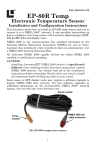
Section 1: Introduction
Thank you for purchasing this Lowrance Radar with the RIM 200 radar
interface module. Your radar consists of three main components: the
radar scanner unit, a display unit (sold separately) and the RIM 200
radar interface module which connects the scanner unit and the display
unit.
We know you’re anxious to begin the installation, but first, let us tell
you how this manual is organized.
The first section describes how your radar works. We'll also discuss issues to consider when selecting an installation location as well as important safety requirements.
The second section will tell you how to install the radar scanner unit.
The third section covers installing the RIM 200 radar interface module.
Radar operation is covered in another manual that corresponds to your
display unit.
The radar scanner unit includes the radar antenna, transmitter, receiver and necessary electronics. The mounting hardware kit and interconnecting cable also are included with the radar scanner.
What is radar?
The word "radar" is an acronym for "RAdio Detecting And Ranging." In
simple terms, this is how it works:
A radio transmitter sends out a quick microwave pulse. A receiver listens for that signal's echo when it is bounced back from something in
its path. When it returns, it is processed by a computer to determine
relative distance, position and bearing of the object that reflected the
signal. This information is displayed on the display unit's screen. Other
boats or ships, navigational markers, landmasses and the like are referred to as targets.
By knowing how long it takes for a signal to return, the distance to a
target can be determined. As the radar antenna scans through a 360
degree rotation, it can show where the target is relative to your position. By repeated scans, you can see which direction another vessel is
moving.
Antenna
How radar will perform is largely determined by its antenna or scanner. Increasing the size of the antenna improves long-range performance and target discrimination — the ability to distinguish two sepa1
rate targets at a distance. The critical factors are the antenna's beam
width and side lobe level. Typically, a radar antenna will radiate a
tightly focused beam from the front of the array. The longer the antenna array is, the narrower the beam width. Additionally, it will also
emit smaller amounts of energy to each side. A lower side lobe level
lessens the effect of a false echo.
Side lobe
The beam radiating the strongest radio signal from the antenna is
called the "main lobe". Those beams radiated in other directions are
referred to as "side lobes". The side lobe level indicates the difference in
level (signal strength) between the largest side lobe and the main lobe.
Characteristics of Radar Wave
Radio waves travel out from the antenna, bending slightly along the
earth's surface. The amount they bend depends on atmospheric conditions. The sight distance of a radar generally is about 6% longer than
the optical sight distance and is calculated using this equation:
Where h is the height of the scanner, the distance to the radar horizon
in nautical miles (Nm)
= 1.22
h(feet)
or
2.21 h(meters)
Targets difficult to display on screen
The intensity of the reflected radio signal from a target depends on the
distance, height, size of the target, the target's material and shape
along with the radar’s transmitter power output and antenna size.
Targets made of fiberglass, wood, or other low-reflectance materials or
those that have a small incident angle are difficult to display on a
screen. Sandy beaches and sandy or muddy shallows can be difficult to
pick up. A coastline can actually be closer to your boat than it appears
on the screen, because there's not much to reflect a signal back to you.
Radar Shadow Zones
Radar waves propagate in a straight line. A high outcropping of land or
a large ship will create a shadow zone behind it and prevent you from
seeing targets on the other side. Radar is a line-of-sight view of targets
and obstructions.
More importantly, if a mast or some part of the boat's superstructure is
in the path of the antenna's sweep, this will also create a shadow zone.
No targets will be recognized behind it and it could create a dangerous
situation.
2
False echoes
Sometimes radar will display targets on screen that do not exist in the
real world. You should be aware of how and why this happens.
A. Ghost echoes
Sometimes one large object very near your boat will appear as two different targets onscreen. One is the actual radar echo. The other is a
ghost echo generated by a re-reflection of the original signal. It comes
back to your own boat, bounces back to the target, and then is picked
up by the antenna on the second bounce.
The actual echo appears at the correct distance and bearing on the
screen. The ghost echo appears somewhere behind your boat. This type
of false echo is also generated by re-reflection of radar waves from
bridges, quay walls or buildings along the shore.
B. Multiple echoes
If there is a large vertical reflecting surface near your boat, as in the
case when you pass alongside a large ship, radar signals are repeatedly
bounced back and forth between your boat and the other object. Two to
four images may appear on the screen at equal intervals in the same
bearing.
This is called a multiple echo. The image appearing closest to you is the
real echo. Multiple echoes will disappear as you move away from the
reflecting object or its bearing changes.
C. False echoes caused by side lobe
An antenna's side lobe emissions are low power, and will not register
distant targets. However, if there is a strong reflecting target near your
boat, it sometimes may appear as a circular-arc false echo on the
screen.
D. Distant false echoes caused by duct phenomenon
The duct phenomenon sometimes occurs when meteorological conditions create a temperature inversion between layers of air. When this
happens, radar waves propagate erratically and can reach a location
considerably farther away from your boat than the radar's maximum
distance range.
What appears onscreen is a false echo that looks to be nearer than the
actual target. Since the true echo from the distant target is outside the
measurement capabilities of the radar, its apparent distance will
change when you change ranges, and you can conclude that it's a false
echo.
3
Radar interference
If another boat's radar is operating on the same frequency as yours, it
can create interference on your display.
The interference usually appears as spiral or radial patterns. This radar has an interference rejection control to eliminate interference. Turn
it on to reduce or eliminate the interference.
Installation Considerations
Prior to actual installation of the radar scanner unit, several factors
must be considered to assure maximum performance.
Location
The scanner must be located so that passengers and crew are not exposed to the direct radar beam.
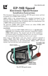
WARNING:
To comply with FCC RF exposure requirements, the radar antenna for this scanner must be installed a minimum distance of 1 foot (0.3 m) or more ABOVE all persons.
This is a bad installation! The radar beam will be obstructed by the
helm. This can create blind spots or shadow zones on the radar display. More importantly, it will expose persons at the helm to harmful
levels of microwave radiation.
4
The scanner unit should be mounted on the center line of your vessel in
a location that has an unobstructed view forward and is as clear as possible the rest of the way around the unit.
A location as high as practical to improve maximum range is desirable,
keeping in mind that minimum range objects may be overlooked if
mounted too high.
Position the unit forward of large structures and exhaust stacks. Large
structures or stacks cause blind spots. Contamination from engine exhaust on the scanner housing also reduces radar performance.
Antennas for GPS, radio communication or other equipment should not
be in the radar beam. Use non-metallic extension poles to move the active area of antennas above the radar beam.
In selecting a location, consider the suitability of the mounting surface.
It must be flat and approximately level with the vessel’s water line. The
surface must support the weight of the scanner and have access to the
underside for installation of the four mounting bolts. (Weights are
listed in the specifications table in the back of this manual.)
Obtaining sufficient dip angle
Raise the scanner position so that there is a sufficient dip angle available between the line of sight from the scanner to the obstacle and the
horizontal line. By raising the dip angle above 5°, it is possible to prevent mid- and long-distance shadow zones. The radar cannot detect objects below the line of sight.
Mounting Base
Use a mounting base such as the one shown below, or you can install
the scanner directly to a roof or other flat surface. Make sure you keep
the water drain tube clear. It's located at the bottom of the scanner
unit.
Note: If the mounting bracket or surface has a curvature of more than
2 mm, use spacers with the mounting bolts to prevent stress on the
scanner housing.
Mounting base for radar scanner unit.
5
The recommended mounting surface thickness is 3/8" to 1/2" (9 mm to
13 mm). If the mounting surface is thin, a doubler should be added. If it
is thicker, longer bolts must be purchased.
WARNING:
The scanner will be damaged if bolts penetrate more
than 9/16" (15 mm).
Also, consider the cable route from the scanner to the operator’s location. Avoid routing the interconnecting cable through areas of possible
damage from moving objects, machinery, exposure to chemicals or high
temperature.
The radar should be installed at least 1 foot above all persons to prevent microwave radiation exposure. This antenna is installed correctly. It safely exceeds the recommended separation distance.
6
Section 2: Radar Installation
Preparations
Unpack your new radar and check the contents against the packing list.
Do not remove the cover from the unit. There are no connections or adjustments inside the unit needed for installation or operation.
The cable must remain attached. For ease of handling, coil the cable
and place it on top of the scanner, then secure it with tape.
WARNING:
To comply with FCC radio frequency (RF) exposure requirements, the radar antenna for this scanner must be
installed a minimum distance of 1 foot (0.3 m) or more
ABOVE all persons.
Radar Antenna Installation Procedure:
Prepare the mounting surface by making sure it is clean and flat.
NOTE:
It is a good idea to check the accuracy of the enclosed paper template by measuring the actual dimension between the hole locations. The printing process and moisture absorption can affect accuracy of the print.
To install radar antenna:
1. Use the template provided and mark the location of the four mounting holes. Align the template squarely with the center line of the vessel,
with the arrow pointing toward the bow.
2. Drill four 1/2" (13 mm) diameter holes through the mounting surface.
3. Check that each bolt (with lock washer and flat washer) protrude
through the mounting surface at least 5/16" (8 mm) but less than 9/16"
(15 mm). If installing a radome model, the bottom of the unit
could be damaged if bolts protrude more than 9/16" (15 mm).
4. Apply marine sealant around each mounting hole.
5. Place the radar scanner unit on the mounting surface. Orient the
scanner with the index mark on the housing facing forward (cable
gland should be facing aft).
6. Install and tighten four M10 x 25U (M10 x 1") mounting bolts. Use
anti-corrosive grease on each bolt to avoid difficulty in removing the
bolts later on.
7. Uncoil the scanner cable.
7
8. Secure the cable near the scanner to support the weight of the cable
and prevent strain on the watertight cable seal. If the cable is to pass
through tubing or a bulkhead, protect the unfinished end. Do not use
the unfinished wires or fabric braid to pull the cable. Attach a fish cord
only to the cable jacket.
9. Route the cable to the RIM 200, securing it at appropriate points
along the way. Make a drip loop and apply sealant at the entry point of
an exterior bulkhead.
Connecting Radar Antenna to Power Source
The following instructions show how to connect radar radome (LRA
1000, LRA 1500 and LRA 2000) and open array (LRA 4000 and LRA
5000) antennas to a power source.
To connect LRA 1000, LRA 1500 and LRA 2000 radome antennas to power:
Antenna large White wire (+) to radar motor power positive
Antenna large Black wire (–) to radar motor power negative
Caution:
If you have a LRA 1000 or LRA 1500, fuse the radar unit's large
White wire (+) with the supplied 5-amp fuse. If your unit is a LRA
2000, fuse the radar unit's large White wire (+) with the supplied 8amp fuse.
To connect LRA 4000 and LRA 5000 array antennas to power:
Antenna large Red wire (+) to magnetron power positive
Antenna large Black wire (–) to magnetron power negative
Antenna large White wire to radar motor power positive
Antenna large Blue wire (–) to radar motor power negative
Caution:
Fuse both the radar unit's large Red wire (+) and large White
wire (+) with the supplied 8-amp fuses.
8
Section 3: RIM 200 Installation
The RIM 200 will replace the power cable that came with your display
unit. Early RIM 200 models have four cables branching out from the
cable plug. The cables include: RIM 200 radar data cable (will be connected to your radar), RIM 200 power cable, display unit power/data
cable and NMEA 2000 network power cable.
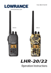
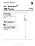
Newer RIM 200 models have three cables branching out from the cable
plug. The cables include: RIM 200 radar data cable (will be connected to
your radar), display unit power cable and NMEA 2000 network power
cable. The three-branch RIM 200 differs from the four-branch model in
that it does not have a RIM 200 power cable.
Three-branch RIM 200
Four-branch RIM 200
RIM 200 model with three cable branches (left). RIM 200 model with
four cable branches (right).
You MUST remove the power cable that came with your unit and
replace it with the RIM 200 to complete this installation.
WARNING:
Even though the RIM 200 is replacing your original
power/data cable, you must follow the same rules, cautions and warnings for powering the display unit and a
NMEA 2000 network or LGC-3000 antenna module. These
details are described in the display unit manual and the
LGC-3000 instruction sheet. Failure to follow all power
connection instructions and fusing requirements could
result in damage to your equipment and injury to you.
1. Route the radar cable to the RIM 200. Connect the RIM 200 radar
data cable to the radar antenna power/data output cable using heatshrink butt connectors. The following pages contain several wiring diagrams. Follow the instructions on the wiring diagram for the type of
radar antenna you have — Detail Drawing A for radome models or De9
tail Drawing C for open array models. Wiring instructions for both array and radome antennas are listed in text format below.
Connecting RIM-200 to LRA 1000, LRA 1500 and LRA 2000 Array antennas:
RIM 200 Brown wire to Radar Antenna Brown wire
RIM 200 Red wire to Radar Antenna Red wire
RIM 200 Yellow wire to Radar Antenna Yellow wire
RIM 200 Orange wire to Radar Antenna Orange wire
RIM 200 Blue wire to Radar Antenna Blue wire
RIM 200 Green wire to Radar Antenna Green wire
Connecting RIM-200 to LRA 4000 and LRA 5000 Radome antennas:
RIM 200 Brown wire to Radar Antenna Brown wire
RIM 200 Red wire to Radar Antenna small Red wire
RIM 200 Yellow wire to Radar Antenna Yellow wire
RIM 200 Orange wire to Radar Antenna Orange wire
RIM 200 Blue wire to Radar Antenna Green wire
RIM 200 Green wire to Radar Antenna small Blue wire
NOTE:
Up to two or three switches may be used for this installation depending on the RIM 200 model you have (three branch or four
branch). These switches prevent cable plug corrosion and the risk of
draining your boat's battery.
2. The RIM 200 works from a 12-volt DC battery system. The display
unit power cable has four wires: red, black, blue and green. You will use
the red and black wires to power your display unit. Attach the red wire
(+) and the black wire (–) to an accessory switch or power bus connected
to a 12-volt battery. If this results in electrical interference, connect
direct to the battery, but install an in-line power switch on the cable.
If possible, keep the power cable away from other boat wiring, especially the engine's wires. This will provide the best isolation from electrical noise. If the cable is not long enough, splice #18 gauge wire onto
it. Make sure to attach the in-line fuse holder to the red lead as close to
the power source as possible. Make sure it is fused with a 3-amp fuse.
3. The blue and green wires (Com port 2) can be used to exchange GPS
position data with any NMEA 0183-compatible device. Connect the display unit power cable blue (TX) transmit wire to the receive (RX) wire
from the NMEA 0183 device.
10
Now connect the display unit power cable green (RX) receive wire to the
transmit (TX) wire from the NMEA 0183 device. There is no ground
wire, so the NMEA 0183 device MUST be grounded to the same
place as the display unit.
NOTE:
If your RIM 200 model has four branches, proceed to Step 4 to
connect the RIM 200 power cable. If your RIM 200 has three
branches, it does not have a RIM 200 power cable, so skip
ahead to Step 5.
4. After you have wired your display unit power, connect the RIM 200
power cable to power in the same manner. The red wire is positive (+)
and the black wire is the ground (–). Be sure to use the 1-amp fuse.
If desired, the RIM 200 power wire and your display unit power wire
can be connected to the same power switchbox.
5. If you are powering a NMEA 2000 network or an LGC-3000 GPS antenna, you must connect the NMEA 2000 power cable. Attach the
NMEA 2000 power cable to an accessory switch that is connected to the
same 12-volt power source as the RIM 200 and display unit power cables. The red wire is positive (+) and the black wire is the ground (–).
Be sure to use the 3-amp fuse.
6. After wires have been connected and any unused wires insulated,
insert the RIM 200 cable plug in the power/data receptacle on the back
of your display unit.
11
Connecting RIM 200 to Radome Antenna
(Four-Branch Installation)
* A power switch will only be connected to the red (+) wire. The black
wire (–) will not be connected to the
power switch.
Display unit
See Detail Drawing C
(Four-Branch Installation)
Cable Plug
*
*
*
*
12V
RIM 200 module
See Detail
Drawing A
RIM 200
data cable
(RS-422)
LRA 1000, LRA 1500 & LRA 2000
Radar Power/data
output cable
12
Radome
antenna
Connecting RIM 200 to Radome Antenna
(Three-Branch Installation)
* A power switch will only be connected to the red (+) wire. The black
wire (–) will not be connected to the
power switch.
Display unit
Cable Plug
See Detail Drawing D
(Three-Branch Installation)
*
*
*
RIM 200 module
12V
See Detail
Drawing A
RIM 200
data cable
(RS-422)
LRA 1000, LRA 1500 & LRA 2000
Radar Power/data
output cable
13
Radome
antenna
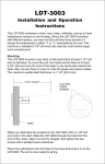
Detail Drawing A
Radar motor power { Large white/pwr + ( fuse)
Large black/pwr –
……………… Shield/Small black ………………..
…………Data Out +/Brown/Data In + ………….
……………Data Out –/Red/Data In – …………..
…………. Data In –/Yellow/Data Out – ……...…
…………. Data In +/Orange/Data Out + ……….
….. SW1 On Signal/Blue/On Signal SW1 …….
……………. SW2+/Green/+V SW2 ……………..
To radar unit
To RIM 200
Detail drawing A: wiring diagram, RIM 200 to radome unit.
NOTE:
If you have a LRA 1000 or LRA 1500, fuse the radar unit's large
white wire (+) with the supplied 5-amp fuse. If your unit is a LRA
2000, fuse the radar unit's large white wire (+) with the supplied 8amp fuse.
14
Connecting RIM 200 to Open Array Antenna
(Four-Branch Installation)
* A power switch will only be connected to the red (+) wire. The
black wire (–) will not be connected to the power switch.
Display unit
See Detail Drawing C
(Four-Branch Installation)
Cable Plug
*
*
*
RIM 200 module
*
*
*
12V
LRA 4000 & LRA 5000
See Detail
Drawing B
Open array
antenna
Radar data
cable (RS-422)
Radar
power/data
output cable
15
Connecting RIM 200 to Open Array Antenna
(Three-branch Installation)
* A power switch will only be connected to the red (+) wire. The
black wire (–) will not be connected to the power switch.
Display unit
See Detail Drawing D:
(Three-Branch Installation)
Cable Plug
RIM 200 module
*
*
*
*
12V
LRA 4000 & LRA 5000
See Detail
Drawing B
Open array
antenna
Radar data
cable (RS-422)
Radar
power/data
output cable
16
Detail Drawing B
Large red + (fuse)
Radar magnetron power { Large
black –
white + (fuse)
Radar motor power { Large
Large Blue –
……………… Shield/Small Black ………………..
……………………… Brown ………………………..
………………………...Red ………………………….
……………………… Yellow ………………………..
……………………… Orange ………………………
Blue
Blue
Green
Green
To radar unit
To RIM 200
Detail drawing B: Wiring diagram, RIM 200 to open array unit.
NOTE:
Fuse both the radar unit's large Red wire (+) and large White wire
(+) with the supplied 8-amp fuses.
17
Switchbox
*
NMEA 2000
power cable
*
18
COM Port 2 (RS232): blue (TX) &
green (RX)
RIM 200 power
cable *
*
Display unit power cable
*
RIM 200 data cable
(RS-422); connects to
radar unit
RIM 200
module
Cable Plug
Detail Drawing C:
Four-branch Installation
*
12 volt
battery
Fuse box
* A power switch will only be
connected to the red (+)
wire. The black wire (–) will
not be connected to the
power switch.
19
RIM 200 data cable
(RS-422); connects to
radar unit
*
Switchbox
*
COM Port 2 (RS232): blue (TX) &
green (RX)
*
Display unit power cable
*
RIM 200
module
Cable Plug
NMEA 2000
power cable
Detail Drawing D:
Three-branch Installation
*
*
12 volt
battery
Fuse box
* A power switch will only be
connected to the red (+) wire.
The black wire (–) will not be
connected to the power
switch.
Notes
20
Notes
21
Notes
22
Lowrance Radar Specifications
Model
LRA-1000
LRA-1500
LRA-2000
LRA-4000
LRA-5000
Radome
1.0 ft.
1.5 ft.
2.0 ft.
N/A
N/A
Diameter
Open Array
N/A
N/A
N/A
4.0 ft.
5.0 ft.
Length
Power
2 kW
2 kW
4 kW
4 kW
4 kW
Output
Power
30 watts
55 watts
70 watts
85 watts
95 watts
Required
Voltage
10.8-41.6
10.8-41.6
10.8-41.6
10.8-41.6
10.8-41.6
Required
volts DC
volts DC
volts DC
volts DC
volts DC
Slotted Wave
yes
yes
yes
open array
open array
Guide Antenna
X-Band
yes
yes
yes
yes
yes
(10 GHz)
Rev. Per Min.
30
30
24
24
24
(RPM)
Operational
100 knots
100 knots
100 knots
70 knots
70 knots
Wind Velocity
Operating
-13˚ to 131˚F -13˚ to 131˚F -13˚ to 131˚F -13˚ to 131˚F -13˚ to 131˚F
Temperature (-25˚ to +55˚C) (-25˚ to +55˚C) (-25˚ to +55˚C) (-25˚ to +55˚C) (-25˚ to +55˚C)
Water
IPX6
IPX6
IPX6
IPX6
IPX6
Resistance
(IEC529)
(IEC529)
(IEC529)
(IEC529)
(IEC529)
Cable
33 ft.
33 ft.
33 ft.
33 ft.
33 ft.
Length
(10 m)
(10 m)
(10 m)
(10 m)
(10 m)
Range
24 nm
24 nm
36 nm
48 nm
48 nm
Warm-up Time
90 sec.
90 sec.
90 sec.
120 sec.
120 sec.
(Worst Case)
Beam Width
7˚
4.7˚
4˚
2.4˚
1.7˚
Horizontal
Beam Width
25˚
25˚
25˚
25˚
25˚
Vertical
Safety
no
no
yes
yes
yes
Zone
14 lb.
15 lb.
17.5 lb.
48.3 lb.
48.3 lb.
Weight
(6.4 kg)
(6.8 kg)
(7.8 kg)
(21.9 kg)
(21.9 kg)
23
FCC Compliance
This device complies with Part 15 of the U.S. Federal Communications Commission (FCC) Rules. Operation is subject to the following two conditions: (1) this device may not cause harmful interference, and (2) this device must accept any interference received, including interference that may cause undesired operation.
Changes or modifications not expressly approved by the manufacturer could void the user's authority to operate the equipment.
Note:
This equipment has been tested and found to comply with the
limits for a Class B digital device, pursuant to Part 15 of the
FCC Rules. These limits are designed to provide reasonable protection against harmful interference in a residential installation.
This equipment generates, uses and can radiate radio frequency
energy and, if not installed and used in accordance with the instructions, may cause harmful interference to radio communications. However, there is no guarantee that interference will not
occur in a particular installation. If this equipment does cause
harmful interference to radio or television reception, which can
be determined by turning the equipment off and on, the user is
encouraged to try to correct the interference by one or more of
the following measures:
•
Reorient or relocate the receiving antenna.
•
Increase the separation between the equipment and receiver.
•
Connect the equipment into an outlet on a circuit different
from that to which the receiver is connected.
•
Consult the factory customer service department for help.
24
LOWRANCE ELECTRONICS
FULL ONE-YEAR WARRANTY
"We," "our," or "us" refers to LOWRANCE ELECTRONICS, INC., the manufacturer of
this product. "You" or "your" refers to the first person who purchases this product as a
consumer item for personal, family or household use.
We warrant this product against defects or malfunctions in materials and workmanship,
and against failure to conform to this product's written specifications, all for one (1) year
from the date of original purchase by you. WE MAKE NO OTHER EXPRESS WARRANTY OR REPRESENTATION OF ANY KIND WHATSOEVER CONCERNING THIS
PRODUCT. Your remedies under this warranty will be available so long as you can show
in a reasonable manner that any defect or malfunction in materials or workmanship, or
any non-conformity with the product's written specifications, occurred within one year
from the date of your original purchase, which must be substantiated by a dated sales
receipt or sales slip. Any such defect, malfunction, or non-conformity which occurs within
one year from your original purchase date will either be repaired without charge or be
replaced with a new product identical or reasonably equivalent to this product, at our
option, within a reasonable time after our receipt of the product. If such defect, malfunction, or non-conformity remains after a reasonable number of attempts to repair by us,
you may elect to obtain without charge a replacement of the product or a refund for the
product. THIS REPAIR, OR REPLACEMENT OR REFUND (AS JUST DESCRIBED) IS
THE EXCLUSIVE REMEDY AVAILABLE TO YOU AGAINST US FOR ANY DEFECT,
MALFUNCTION, OR NON-CONFORMITY CONCERNING THE PRODUCT OR FOR
ANY LOSS OR DAMAGE RESULTING FROM ANY OTHER CAUSE WHATSOEVER.
WE WILL NOT UNDER ANY CIRCUMSTANCES BE LIABLE TO ANYONE FOR ANY
SPECIAL, CONSEQUENTIAL, INCIDENTAL, OR OTHER INDIRECT DAMAGE OF
ANY KIND.
Some states do not allow the exclusion or limitation of incidental or consequential damages, so the above limitations or exclusions may not apply to you.
This warranty does NOT apply in the following circumstances: (1) when the product has
been serviced or repaired by anyone other than us; (2) when the product has been connected, installed, combined, altered, adjusted, or handled in a manner other than according to the instructions furnished with the product; (3) when any serial number has been
effaced, altered, or removed; or (4) when any defect, problem, loss, or damage has resulted
from any accident, misuse, negligence, or carelessness, or from any failure to provide
reasonable and necessary maintenance in accordance with the instructions of the owner's
manual for the product.
We reserve the right to make changes or improvements in our products from time to time
without incurring the obligation to install such improvements or changes on equipment
or items previously manufactured.
This warranty gives you specific legal rights and you may also have other rights which
may vary from state to state.
REMINDER: You must retain the sales slip or sales receipt proving the date of your
original purchase in case warranty service is ever required.
LOWRANCE ELECTRONICS
12000 E. SKELLY DRIVE, TULSA, OK 74128
(800) 324-1356
25
How to Obtain Service…
…in the USA:
We back your investment in quality products with quick, expert service
and genuine Lowrance parts. If you're in the United States and you
have technical, return or repair questions, please contact the Factory
Customer Service Department. Before any product can be returned, you
must call customer service to determine if a return is necessary. Many
times, customer service can resolve your problem over the phone without sending your product to the factory. To call us, use the following
toll-free number:
800-324-1356
8 a.m. to 5 p.m. Central Standard Time, M-F
Lowrance Electronics may find it necessary to change or end our shipping policies, regulations, and special offers at any time. We reserve the
right to do so without notice.
…in Canada:
If you're in Canada and you have technical, return or repair questions,
please contact the Factory Customer Service Department. Before any
product can be returned, you must call customer service to determine if
a return is necessary. Many times, customer service can resolve your
problem over the phone without sending your product to the factory. To
call us, use the following toll-free number:
800-661-3983
905-629-1614 (not toll-free)
8 a.m. to 5 p.m. Eastern Standard Time, M-F
…outside Canada and the USA:
If you have technical, return or repair questions, contact the dealer in
the country where you purchased your unit. To locate a dealer near
you, visit our web site, www.lowrance.com and look for the Dealer Locator.
26
Accessory Ordering Information
for all countries
To order Lowrance accessories for your radar, please contact:
1) Your local marine dealer or consumer electronics store. Most quality
dealers that handle marine electronic equipment or other consumer
electronics should be able to assist you with these items.
To locate a Lowrance dealer near you, visit our web site,
www.lowrance.com and look for the Dealer Locator. Or, you can consult
your telephone directory for listings.
2) U.S. customers: LEI Extras Inc., PO Box 129, Catoosa, OK 74015-0129
Call 1-800-324-0045 or visit our web site www.lei-extras.com.
3) Canadian customers can write:
Lowrance/Eagle Canada, 919 Matheson Blvd. E. Mississauga, Ontario
L4W2R7 or fax 905-629-3118.
Shipping Information
If it becomes necessary to send a product for repair or replacement, you
must first receive a return authorization number from Customer
Service. Products shipped without a return authorization will not be
accepted. When shipping, we recommend you do the following:
1. Please do not ship the knobs or mounting bracket with your unit.
2. If you are sending a check for repair, please place your check in an
envelope and tape it to the unit.
3. For proper testing, include a brief note with the product describing
the problem. Be sure to include your name, return shipping address
and a daytime telephone number. An e-mail address is optional but
useful.
4. Pack the unit in a suitable size box with packing material to prevent
any damage during shipping.
5. Write the Return Authorization (RA) number on the outside of the
box underneath your return address.
6. For your security, you may want to insure the package through your
shipping courier. Lowrance does not assume responsibility for goods
lost or damaged in transit.
Visit our web site:
Lowrance Pub. 988-0161-042
Printed in USA 062707
© Copyright 2007
All Rights Reserved
Lowrance Electronics, Inc.