1
EB-EWU-02
USER’S INFORMATION MANUAL
HOT WATER HEATING BOILERS
DOMESTIC WATER HEATERS
150,000 - 300,000 Btu/hr MODELS
IMPORTANT
INSTALLER - AFFIX INSTALLATION
MANUAL ADJACENT TO THE BOILER
CONSUMER - RETAIN THE USER’S
INFORMATION MANUAL FOR FUTURE
REFERENCE
WARNING
If the information in this manual is not followed
exactly, a fire or explosion may result causing
property damage, personal injury or loss of life.
This appliance MUST NOT be installed in any
location where gasoline or flammable vapors are
likely to be present.
DO NOT Use this appliance if any part has been
under water. The possible damage to a flooded
appliance can be extensive and present numerous
safety hazards. Any appliance that has been under
water must be replaced.
LIGHTING INSTRUCTIONS
FOR YOUR SAFETY,
READ BEFORE OPERATING
WARNING
If you do not follow these instructions exactly, a
fire or explosion may result causing property
damage, personal injury or loss of life.
1. This appliance does not have a pilot. It is equipped with
an ignition device which automatically lights the
burner. Do not try to light the burner by hand.
WHAT TO DO IF YOU SMELL GAS
•
•
•
•
•
Do not try to light any appliance.
Do not touch any electric switch; do not use any
phone in your building.
Immediately call your gas supplier from a
neighbors phone. Follow the gas supplier’s
instructions.
If you cannot reach your gas supplier, call the fire
department.
Installation and service must be performed by a
qualified installer, service agency or the gas
supplier.
USER WARNING
The information contained in this manual is
intended for use by qualified professional installers,
service technicians or gas suppliers. Consult your local
expert for proper installation or service procedures.
WARNING
Should overheating occur or the gas supply fail to
shut off, do not turn off or disconnect the electrical
supply to the pump. Instead, shut off the gas supply
at a location external to the appliance.
2. BEFORE OPERATING, smell around the appliance
area for gas. Be sure to smell next to the floor because
some gas is heavier than air and will settle to the floor.
3. Use only your hand to turn the gas control lever. Never
use tools. If the lever will not turn by hand, don't try to
repair it, call a qualified service technician. Force or
attempted repair may result in a fire or explosion.
4. Do not use this appliance if any part has been under
water. Immediately call a qualified service technician
to inspect the appliance and to replace any part of the
control system and any gas control which has been under
water.
LIGHTING INSTRUCTIONS
TO TURN OFF GAS TO APPLIANCE
1. STOP! Read the safety information above.
1. Turn off all electric power to the appliance if service is
to be performed.
2. Turn off all electrical power to the appliance.
2. Turn the gas control knob on the gas valve clockwise to
the "OFF" position. Do not force.
3. Remove the upper front access panel
WARNING
4. Turn the power switch on the inside of the cabinet to
"OFF" position.
Should overheating occur or the gas fail to shut
off, do not turn off or disconnect the electric
supply to the pump. Instead, shut off the gas
supply at a location external to the appliance.
5. Set the thermostat to the lowest setting.
6. This appliance is equipped with an ignition device which
automatically lights the burners. DO NOT try to light
the burners by hand.
HOT SURFACE IGNITION SYSTEM
7. Turn the gas control knob on the gas valve clockwise to
the "OFF" position.
The hot surface ignition module is not repairable. Any
modification or repairs will invalidate the warranty and
may create hazardous conditions that result in property
damage, personal injury, fire, explosion and/or toxic gases.
A faulty ignition module must be replaced with a new unit.
The hot surface igniter is also the flame sensor.
Call a qualified service technician if service is required on
the hot surface ignition system.
WATER CONNECTIONS
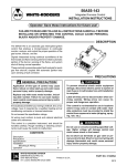
FIG. 1 Combination Gas Valve
8. Wait five (5) minutes to clear out any gas. If you smell
gas, STOP! Follow the instructions in the safety
information "What To Do If You Smell Gas". If you
don't smell gas, go on to the next step.
9. Turn the gas control knob on the gas valve
counterclockwise to the "ON" position.
10. Set the thermostat to the desired setting.
11. Turn the power switch on the inside of the cabinet to the
“ON” position.
12. Replace control access panel.
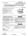
FIG. 2 Water Connections
13. Turn on all electrical power to the appliance.
Inlet and Outlet Connections
14. If the appliance will not operate, follow the instructions
"To Turn Off Gas To Appliance" and call your service
technician or gas supplier.
For ease of service, install unions on inlet and outlet of the
appliance. The connection to the appliance marked "Inlet"
on the header should be used for return from the system.
The connection on the header marked "Outlet" is to be
connected to the supply side of the system.
2
WARNING
RELIEF VALVE
Using other vent or air intake materials, failure
to properly seal all seams and joints or failure to
follow vent pipe manufacturer's instructions can
result in personal injury, death or property
damage. Mixing of venting materials will void
the warranty and certification of the appliance.
This appliance is supplied with a relief valve(s) sized in
accordance with ASME Boiler and Pressure Vessel Code,
Section IV ("Heating Boilers"). The relief valve(s) is
installed in the vertical position and mounted in the hot
water outlet. No valve is to be placed between the relief
valve, and the appliance. To prevent water damage, the
discharge from the relief valve shall be piped to a suitable
floor drain for disposal when relief occurs. No reducing
couplings or other restrictions shall be installed in the
discharge line. The discharge line shall allow complete
drainage of the valve and line. Relief valves should be
manually operated at least once a year.
IMPORTANT:
Examine the venting system at least once a year.
Check all joints and vent pipe connections for
tightness. Also check for corrosion or
deterioration. Immediately correct any problems
observed in the venting system.
CAUTION
COMBUSTION AND VENTILATION AIR
REQUIREMENTS FOR
CONVENTIONALLY VENTED
APPLIANCES
Avoid contact with hot discharge water.
VENT SYSTEM OPTIONS
This appliance has five venting options. They are:
Provisions for combustion and ventilation air must be in
accordance with Section 5.3, Air for Combustion and
Ventilation, of the latest edition of the National Fuel Gas
Code, ANSI Z223.1, in Canada, the latest edition of CGA
Standard B149 Installation Code for Gas Burning
Appliances and Equipment, or applicable provisions of the
local building codes.
1. Conventional Negative Draft Venting
Conventional negative draft venting with vertical
termination.
2. E+ with a Vertical Conventional Vent
E+Vent with a vertical conventional vent for flue
products and a combustion air pipe from either the
sidewall or roof top.
CAUTION
3. Direct Venting with Sidewall Terminations
Direct vent with sidewall terminations for flue
products and combustion air.
Under no circumstances should the equipment room
ever be under a negative pressure. Particular care
should be taken where exhaust fans, attic fans, clothes
dryers, compressors, air handling units, etc., may take
away air from the unit.
4. Direct Venting with Vertical Terminations
Direct vent with vertical through-roof
terminations for flue products and combustion air.
E+ Vent and Direct Vent Units
5. Outdoor Installation
Outdoor installation consists of the installation of
a special vent cap / top assembly, gas valve cover,
deflectors, and a weatherproof junction box.
These optional venting systems use two pipes, one pipe to
exhaust flue products and one pipe to supply combustion
air directly to the appliance. The optional vent systems
have specific material and installation requirements. The
combustion air pipe for the optional vent systems may
terminate horizontally with a sidewall air inlet or vertically
with a rooftop air inlet, based on the venting system
installed. A detailed explanation of the installation
requirements for each venting system, components used
and part numbers of vent kits for each model is included in
the Installation and Service Manual. No additional
combustion air openings are required for the mechanical
room when the optional two pipe venting systems are
properly installed.
All appliances are shipped from the factory
equipped for conventional negative draft venting.
All other optional vent systems require the
installation of specific vent kits and venting
materials. See the Installation and Service Manual
for a detailed explanation of the installation
requirements for each venting system, components
used and part numbers of vent kits for each model.
3
The combustion air supply must be completely free of any
chemical fumes which may be corrosive to the appliance.
Common chemical fumes which must be avoided are
fluorocarbons and other halogenated compounds, most
commonly present as refrigerants or solvents, such as
Freon, trichlorethylene, perchlorethylene, chlorine, etc.
These chemicals, when burned form acids which quickly
attack the heat exchanger finned tubes, tube headers, flue
collectors, and the vent system. The result is improper
combustion and a non-warrantable, premature appliance
failure.
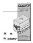
TABLE - A
IGNITION MODULE
INDICATING LIGHTS
Indicating Light
EXHAUST FANS: Any fan or equipment which exhausts
air from the mechanical room may deplete the combustion
air supply and/or cause a down draft in the venting system.
Spillage of flue products from the venting system into an
occupied living space can cause a very hazardous condition
that must be immediately corrected. If a fan is used to
supply combustion air to the boiler room, the installer must
make sure that it does not cause drafts which could lead to
nuisance operational problems with the appliance.
OPERATION AND
DIAGNOSTIC LIGHTS
Function
Power on Switch
- On - 120 VAC supplied to unit
Power LED
- On - Module is powered from 24
VAC system and operating
properly
- Blinks continuously if voltage is
too high on transformer secondary
- Off - Module is not powered
Purge LED
- Off - Combustion air fan is not
powered OR air flow is not proven
- On - When unit is in prepurge or
interpurge
- Blinks continuously when there is
a pressure switch fault
Ignitor LED
Valve LED
Flame LED
- Off - Igniter is off
- On - When hot surface igniter is on
- Off - Gas valve is closed
- On - Control signaling gas valve
is on
- Blinks continuously when control
is in LOCKOUT because it failed
ignition
- Off - Flame is not present
- On - Control signaling flame is
present
- Blinks continuously when L1 and
neutral are reversed
MAINTENANCE
Listed below are items that must be checked to ensure safe
reliable operations. Verify proper operation after servicing.
FIG. 3 Ignition Module
CAUTION
The unit has a lighted ON/OFF power switch on the outer
cabinet (left side) and five (5) LED indicators on the
electronic ignition control module to monitor the units
operation.
Label all wires prior to disconnection when
servicing controls. Wiring errors can cause
improper and dangerous operation.
1. Examine the venting system at least once a year. Check
more often in first year to determine inspection interval.
Check all joints and pipe connections for tightness,
corrosion or deterioration. Clean screens in the venting
air intake system as required. Have the entire system,
including the venting system, periodically inspected by
a qualified service agency.
4
2. Using the view port, located below the water
connections, visually check main burner flames at each
start up after long shutdown periods or at least every six
months.
4. Flue Gas Passageways Cleaning Procedures: Any sign
of soot at the burners indicate a need for cleaning. The
following cleaning procedure must only be performed
by a qualified serviceman or installer. Proper service is
required to maintain safe operation. Properly installed
and adjusted units seldom need flue cleaning.
WARNING
This area is hot and direct contact could result in
burns.
All gaskets on disassembled components must be replaced
with new gaskets on reassembly. Gasket kits are available
from your distributor.
a.
Turn off main power to appliance.
b.
Turn off main manual gas shutoff to appliance.
c.
Remove the front outer jacket panels.
d.
Remove gas valve from the manifold.
e.
Remove screws from manifold mounting
brackets. Pull manifold(s) / orifice assembly away from
burners. Remove hose from burner tap.
f.
Remove mounting screws from each burner and
slide burner out toward front of appliance. Use caution
to prevent damage to burner gaskets, refractory, hot
surface igniter or wiring.
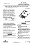
FIG. 4 Burner Flame Patterns
a. Normal Flame: A normal flame is blue, with
slight yellow tips, with a well defined inner
cone and no flame lifting.
g.
Remove soot from burners with a stiff bristle
brush. Damaged burners or burner gaskets must be
replaced.
b. Yellow Tip: Yellow tip can be caused by
blockage or partial obstruction of air flow to
the burner(s).
HEAT EXCHANGER CLEANING
c. Yellow Flames: Yellow flames can be caused
by blockage of primary air flow to the
burner(s) or excessive gas input. This
condition MUST be corrected immediately.
5. Check the heat exchanger surface for sooting. If
present, heat exchanger must be cleaned and problem
corrected. Proceed as follows.
a.
Remove manifold/orifice assembly as described
in steps “a” through “e” in “Burner Removal” in the
Installation and Service Manual.
d. Lifting Flames: Lifting flames can be caused
by over firing the burner(s) or excessive
primary air.
If improper flame is observed, examine the venting system,
ensure proper gas supply and adjust the combustion air.
b.
Disconnect wiring from hot surface igniter and
hose from burner tap.
3. Combustion Air Shutter Adjustment: This appliance
uses a fan assisted combustion process. The fan air
shutter is factory pre-set and should not need
adjustment in most cases. If adjustment is required, the
fan air shutter may be manually adjusted to a dimension
specified for each model.
c.
Remove inner combustion chamber door mounting
screws, tilt slightly and slide door assembly out toward
front of appliance. Use caution to prevent damage to
refractory, hot surface igniter, hose and wiring.
d.
Check "V" baffles on top of heat exchanger.
Remove and clean if necessary.
e.
Remove soot from heat exchanger with a stiff
bristle brush. Use a vacuum to remove loose soot from
surfaces and inner chamber.
5
f.
Carefully reinstall combustion chamber door,
jacket panels, dividers, burners, manifolds wires and
hoses. Use new gasket material for proper air seal.
g.
Reassemble and test for gas leaks.
h.
Cycle appliance and check for proper operation.
Temperature Control Settings
There are three setting knobs on the temperature control
unless your appliance is specified as a boiler only with an
outdoor air reset option. If your appliance is a boiler only
with an outdoor air reset option, there are additional
controls for this option. They are explained under Outdoor
Air Reset Option, page 7.
An appliance installed in a dust or dirt contaminated
atmosphere will require cleaning of the burners on a 3 to 6
month schedule or more often, based on severity of
contamination. Contaminants can be drawn in with the
combustion air. Non-combustible particulate matter such
as dust, dirt, concrete dust or dry wall dust can block burner
ports and cause non-warrantable failure Use extreme care
when operating an appliance for temporary heat during
new construction. The burners and fan will probably
require a thorough cleaning before the appliance is placed
in service.
The three setting knobs on the temperature control are for
Set point, Differential, and High-Fire Offset (see Figure 5).
6. Combustion Air Fan: The combustion air fan should be
checked every 6 months. Clean as required when
installed in a dust or dirt contaminated location.
7. Water Circulating Pump: Inspect pump every 6 months
and oil as necessary. Use SAE 30 non-detergent oil or
lubricant specified by pump manufacturer.
FIG. 5 Temperature Control
Maximum Set Point Determination
8. Keep appliance area clear and free from combustible
materials, gasoline and other flammable vapors and
liquids.
The maximum set point for the control is factory set.
Boilers can be set to 240°F max., water heaters are set to
190°F max., and specialty state and local codes to 200°F.
These maximum set points are established by cutting the
OJ1 and OJ2 jumpers located on the right side of the
temperature controller. The maximum set point is
determined as shown below in TABLE-B.
9. Check frequently to be sure the flow of combustion and
ventilation air to the boiler is not obstructed.
TEMPERATURE ADJUSTMENT
TABLE B
Maximum Set point Determination
Operating Temperature Control
NOTE:
The temperature controller is pre-set at the factory
with test settings. You may need to adjust the
settings to meet your specific needs.
WARNING
Return water temperatures must not be less than
140°F. If lower return water temperatures are
required, follow the instructions in the Low
Temperature Bypass Requirements or Three-Way
Valves section(s) in the Installation and Service
Manual.
OJ1
OJ2
Max.
Set Point
Connected
Connected
240°F
Cut
Connected
190°F
Connected
Cut
200°F
Cut
Cut
160°F
NOTE:
Anytime that OJ1 is the only jumper cut, a new
overlay is required under the Set Point knob on the
temperature controller because the scale has changed
to a maximum of 190°F.
Anytime the OJ2 jumper is cut (with or without OJ1),
a new overlay is required under the Set Point knob on
the temperature controller because the scale has
changed to a maximum of 200°F.
Locating Temperature Control
Remove the control panel door on the front of the appliance
in order to locate and access the temperature control.
6
Set Point
The Set Point knob specifies the target water temperature
in degrees, Fahrenheit. After the water temperature reaches
the set point, the temperature control shuts off the burners.
Shutdown
Differential
The Differential specifies the number of degrees below the
set point that the control will allow the water temperature
to drop before it brings the appliance back on again.
Outdoor Air Max (O.A. Max)
The O.A. Max knob allows a reset up to the maximum
outdoor air temperature specified by this knob setting. At
any outdoor air temperature above the specified setting, the
appliance will not reset but will continue to run at the set
point temperature.
The Shutdown knob specifies the outdoor air lockout
temperature at which the control would prevent the
appliance from operating.
High-Fire Offset
The temperature control operates a two-stage firing system.
The two stages are High-Fire and Low-Fire. High-Fire
operates all burners while Low-Fire operates
approximately one-half of the burners.
The High-Fire knob specifies the number of degrees below
set point that the High-Fire stage shuts down. At that point,
the appliance will continue to operate at the Low-Fire stage
until the set point is reached.
The High-Fire offset knob has settings between 0°F and
20°F. If set at 0°F, the High-Fire offset is disabled and the
appliance will operate at the High-Fire stage until the set
point is reached and the temperature control shuts the
appliance off.
No matter what the High-Fire offset knob is set to, the
appliance will light at Low Fire and operate for
approximately 10 to 120 seconds before the High-Fire
stage actuates.
Ratio
The Ratio knob allows control over the reset ratio to be
used during Outdoor Air Reset. The allowable ratios are as
low as 0.5:1 or as high as 1.5:1.
Selecting the 0.5:1 ratio will increase the set point 0.5°F for
every 1.0°F drop in outdoor air temperature up to the
maximum set point temperature.
Selecting the 1.5:1 ratio will increase the set point 1.5°F for
every 1.0°F drop in outdoor air temperature up to the
maximum set point temperature.
See Figure 7 for an outdoor air reset chart example.
OUTDOOR AIR RESET OPTION
Outdoor Air Reset Option
For boilers ordered with the Outdoor Air Reset option,
there is an additional control (FIG. 6). There are three
setting knobs for Shutdown, Outdoor Air Max., and Ratio.
There is also a switch to turn the outdoor air shutdown
feature On or Off. An O.A. Sensor is also included.
D4
CN8
55
45
CN1
65
VR3
W1
CN2
60
40
70
SHUTDOWN
55
50
60
O.A. SENSOR
ON ENABLE
CN3
OJ1
C10
50
CN4
SW1
DISABLE
O.A. SHUTDOWN
CN5
OJ2
R6
R4
C7
(c)2002 L.C.
CN7
J4
C9
0.9 1.01.1
CN6
1.2
0.8
1.3
45
65 0.7
W3
1.4
0.6
VR1
VR2
0.5
1.5 W1 W2
40
70
CN1
RATIO
O.A. MAX.
CN9
160
9 10 11
10
200
12
8
140
15
5
13
7
220 6
14
120
5 VR2 15
(F-)0 VR3 20
240
DIFFERENTIAL
HIGH-FIRE
OFF
TST2314
OFFSET
SETPOINT
R8
FIG. 7 Outdoor Air Control Example Chart
R15
R16
Outdoor Air Shutdown Enable/Disable Switch
The Outdoor Air Shutdown Enable/Disable switch turns
the outdoor air shutdown feature On and Off. Disabling the
Outdoor Air Shutdown feature allows the appliance to
operate regardless of the outdoor air temperature. This is
needed for indirect domestic hot water systems for
example.
FIG. 6 Optional Outdoor Air Reset Control
7
2/05 Printed in the U.S.A.