1
Lighting Systems
1BHFPG
RT6-7
-ZUFUVCF*OEJSFDU-JHIU51FS'PPU4FDUJPO
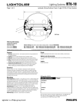
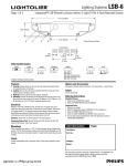
6" (15.24cm)
4
2
1
Half Scale
3
6
5
Ordering Information
Lytetube Indirect Open w/Track :
4 Foot Joiner: RT632742
8 Foot Joiner: RT632782
Complete ordering instructions on back.
Ballast & Voltage (add code to end of base catalog number - Example: RT632782E82)
E81 = T8 Electronic 120v
HD1 = T8 Electronic PowerSpec Dimming 120v
M71 = T8 Electronic Dimming 120v
E82 = T8 Electronic 277v
HD2 = T8 Electronic PowerSpec Dimming 277v
M72 = T8 Electronic Dimming 277v
For all fixtures represented in this family please refer to the brochure and/or additional specification sheets.
Features
Finish
1. Housing: Extruded aluminum. 1/8" (0.32cm) aluminum end cap attached with
no exposed fasteners.
2. Lamping: Two T8 32 watt fluorescent lamps. Provided by others.
3. Reflector: Precision die-formed high gloss baked white enamel reflector.
4. Lens: Extruded clear acrylic linear ribbed lens.
5. Lytespan: Pre-wired Basic 1-circuit track. 20 amps at 120v (pre-wired with lamp
on Indirect/Track unit).
6. Alignment/Locking Mechanism: Heavy gauge steel bracket with integral
splines for alignment of housing modules, joins modules tightly together
without removing any luminaire component at time of installation.
Powder coated baked white enamel. Custom colors available, consult factory.
Options and Accessories
L, T, X, Inline joiner blocks, emergency battery packs, dual switching and fusing
available.
Labels
UL, cUL and I.B.E.W.
Electrical
Specify 120 volt or 277 volt. 3 conductor, 18 gauge wire. Color-coded quick
connectors allow ease of connection for joiner modules. For special circuiting,
consult factory. Rapid start, HPF, class "P" thermally protected. PowerSpec HDF
dimming ballast is available. Factory installed ballast disconnect allows the ballast
to be disconnected from and reconnected to incoming power under load without
turning the entire circuit off.
Mountings
Cable Suspension (not shown)- 1-1/2" (3.81cm) or 4-1/2" (11.43cm) diameter flat
canopy finished enamel white, 3/16" (0.48cm) diameter x 4" (10.16cm) stabilizing
tube (polished chrome finish), 1/16" (0.16cm) diameter stainless steel aircraft cable
adjustable up to 36" (91.44cm), adjustable cable gripper. Available with both white
jacketed straight or coiled cord. Feed locations require a 4-1/2" (11.43cm) canopy.
Coiled cord not available in dual switching or emergency battery backup.
Stem Mounting (not shown) - 4-1/2" (11.43cm) diameter flat canopy, 1/2"
(2.08cm) diameter stem. Chrome plate or white finish. Can be cut to length on job.
Self-aligning swivel provides adjustability up to 38°. The stem assembly shall meet
or exceed the requirements set forth in the State of California Uniform Building
Code for suspended lighting fixtures installed in seismic zone four.
Wall Mounting (not shown) - consult factory for availability.
US Patent No. 4,717,993.
Job Information
Type:
Job Name:
Cat. No.:
Lamp(s):
Notes:
"JSQPSU3PBE'BMM3JWFS."t
t'BY
We reserve the right to change details of design, materials and finish.
XXXMJHIUPMJFSDPN½1IJMJQT(SPVQt #
Lighting Systems
1BHFPG
RT6-7
-ZUFUVCF*OEJSFDU-JHIU51FS'PPU4FDUJPO
Performance and Quick Calculator
CANDLEPOWER
155˚
145˚
135˚
1000
ZONE
Deg.
180
175
165
155
145
135
125
115
105
95
90
85
75
65
55
45
35
25
15
5
0
125˚
800
115˚
600
400
105˚
200
95˚
0
90˚
200
85˚
400
75˚
600
65˚
800
55˚
1000
22
45
67
90
763
758
739
681
601
474
368
221
89
14
0
0
0
0
0
0
0
0
0
0
0
763
762
814
841
809
690
582
429
236
71
47
28
12
4
2
0
0
0
0
0
0
763
776
916
942
929
848
796
566
320
99
57
38
25
19
7
3
1
0
0
0
0
763
794
970
1015
1045
999
898
616
356
109
67
48
40
29
13
4
3
0
0
0
0
763
800
978
1035
1078
1042
885
628
360
109
69
58
42
31
15
5
3
0
0
0
0
1200
0˚ 5˚
15˚
25˚
35˚
45˚
ZONE
REPORT NO: LRL 489-10E
LAMPS: 2-32WT8
LUMENS: 2900
EFFICIENCY: 62.0%
COEFFICIENTS OF UTILIZATION
0
0-90
90-180
0-180
8-FOOT JOINER
48" (121.92cm)
96" (243.84cm)
80
91
3506
3597
1.6
60.4
62.0
2.5
97.5
100.0
0
1
2
3
4
5
6
7
8
9
10
50
59
51
44
39
34
30
27
24
22
19
18
30
59
49
41
35
30
26
22
19
17
15
14
70
% WALL REFLECTANCE
10 50
30
10
59 41
51
51
47 44
42
40
38 38
35
33
31 33
30
27
26 29
26
23
22 26
22
19
19 23
19
16
16 21
17
14
14 19
15
12
12 17
13
11
11 15
12
9
50
50
35
30
26
23
20
18
16
14
13
12
11
30
35
29
25
21
18
16
13
12
10
9
8
10
35
28
23
19
16
14
12
10
9
8
7
SPACING RATIOS: PARALLEL = 1.3 / PERPENDICULAR = 1.5
ZONAL LUMEN SUMMARY
LUMENS % BARELAMP % LUMINAIRE
Fixture Lengths & Mounting Locations
4-FOOT JOINER
% EFFECTIVE CEILING CAVITY REFLECTANCE
ROOM SURFACE REFLECTANCES: 80% CEILING, 50% WALLS, 20% FLOOR
120
INITIAL FOOTCANDLES
165˚
ROOM CAVITY RATIO
CANDLEPOWER CURVE
180˚ 175˚
1200
2000 LUMENS PER LAMP
RCR = 1 (Rm. Width = 10xMtg. Ht. above work plane)
RCR = 5 (Rm. Width = 2xMtg. Ht. above work plane)
RCR = 10 (Rm. Width = Mtg. Ht. above work plane)
100
80
60
40
20
20
3
4
5
40
6
60
80
100
120
AREA PER FIXTURE IN SQUARE FEET
7
8
9
10
11
140
160
12
13
CENTER TO CENTER DISTANCE OF FIXTURES IN FEET
Sample Run
96" (243.84cm)
POWER FEED
END SET
48" (121.92cm)
96" (243.84cm)
SINGLE
STEM OR CABLE
8-FOOT JOINER
SINGLE
STEM OR CABLE
20' 6" (624.84cm)
8-FOOT JOINER
6“ (15.24cm)
3"
9" (22.86cm)
12” (30.54cm)
18” (45.72cm)
24” (60.96cm)
3"
Power Feed End Set
Chrome Stem
RT62 ED12 = 12" OAL
RT62 ED18 = 18" OAL
RT62 ED24 = 24" OAL
Add WH for
white stem
Power Feed End Set
Cable/Cord
RT62 EDCC36
(straight cord)
RT62 EDCCC36
(coiled cord)
Max 10 amps.
9"
12"
6"
9"
"L" Joiner Block
RT62-LD
Single Stem
Chrome
S12 = 12" OAL
S18 = 18" OAL
S24 = 24" OAL
Add WH for
white stem
6"
Cable Assemblies
C36 (cable only)
CC36 (cable/straight
cord feed)
CCC36 (cable/coiled
cord feed)
12"
6"
6"
9"
"T" Joiner Block
RT62-TD
Inline joiner block available: RT62ILD
6"
3” (7.62cm) END SET
4-FOOT JOINER
Dimensions given are both fixture
lengths and mounting distances.
Ordering Instructions
Mounting & Joiner Block Accessories
3” (7.62cm)
SINGLE
STEM OR CABLE
9"
"X" Joiner Block
RT62-XD
Individual Fixtures:
1. Order number of JOINER FIXTURES.
2. Order one POWER FEED END SET per fixture.
3. Order one SINGLE STEM or CABLE ASSEMBLY per JOINER FIXTURE.
Continuous Rows:
1. Determine run length.
2. Order the appropriate number of JOINER FIXTURES for the complete run.
3. Order one POWER FEED END SET per run.
4. Order one SINGLE STEM or CABLE ASSEMBLY per JOINER FIXTURE.
5. For cable mounted runs that exceed amperage limits, order the appropriate
number of CABLE/CORD FEEDS.
Square/Rectangle Patterns:
1. Order appropriate number of JOINER FIXTURES to complete the pattern size.
2. Order number and type of JOINER BLOCKS required.
3. Order one SINGLE STEM or CABLE ASSEMBLY per JOINER FIXTURE.
4. For cable mounted patterns that exceed amperage limits, order the appropriate
number of CABLE/CORD FEEDS.
6"
Job Information
Type:
"JSQPSU3PBE'BMM3JWFS."t
t'BY
We reserve the right to change details of design, materials and finish.
XXXMJHIUPMJFSDPN½1IJMJQT(SPVQt #