Transcript
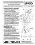
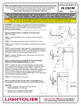
ISF:302 INSTRUCTION SHEET 12-01/Rev-04 INSTALLATION INSTRUCTIONS 12V LOW VOLTAGE AND 120V MOUNTING FRAME READ AND UNDERSTAND THESE INSTRUCTIONS BEFORE INSTALLING FIXTURE This fixture is intended for installation in accordance with National Electrical Code or Canadian Electrical Code (as applicable) and local regulations. To ensure full compliance with local codes and regulations, check with your local electrical inspector before installation. To prevent electrical shock, turn off electricity at fuse box before proceeding. Retain these instructions for maintenance reference. 302MR - 402MR 302ES MOUNTING FRAME BUILT-IN NAILER WOOD JOIST MOUNTING BAR LOCKING TAB MOUNTING BAR FIG.1 A. MOUNTING BAR: For new ceilings Note-1: The mounting bars are extensible from 12-1/2 to 27-1/4 max. for 302MR, 302ES model and 29 for 402MR model. Note-2: For off-centre installation, use the 20 expandable mounting bars (Nº1964, order separately). 1. Insert the mounting bars into the proper openings on the short side or the long side of the mounting frame. (Fig.2) 2. Align the mounting bar with the bottom edge of the wood joist. (Fig.1) 3. Push in the built-in nailer. (Fig.1) FLEXIBLE WIRE "PRY-OUT" PLUG LOCKING CLIP MOUNTING FRAME MOUNTING BAR FIG.2 WIRE CLAMP FIG.3 JUNCTION BOX FIG.4 LAMP C. MOUNTING FRAME: 1. Install the locking clip. (Fig.3) Note-1: The locking clip is also available separately (Nº0098, order separately). Note-2: To lock more securely into place fold the locking tabs. (Fig.2) LAMP THERMAL PROTECTOR JUNCTION BOX TRIM: Install the trim using the appropriate sheet. NOTE: WARNING RISK OF FIRE Transformer contains fixture thermal protector. Use only replacement transformer obtained from LIGHTOLIER. WHITE LOW VOLTAGE TRANSFORMER BLUE JUNCTION BOX FIG.5 (302MR) THERMAL PROTECTOR FIG.6 (302ES) GROUND NEUTRAL (white) INPUT (120V) D. WIRE-IN: 1. Remove the appropriate "Pry-out plug". 2. Insert the supply lead into the junction box: a) If using FLEXIBLE CONDUIT: Use a BX connector (not provided). b) If using FLEXIBLE WIRE: Insert under the wire clamp. (Fig.4) 3. Connect the ground lead. (Fig.5,6,7) 4. Connect the white leads (NEUTRAL) together, and the black leads (120V) together. (Fig.5,6,7) E. CEILING: 1. Cut a hole in the ceiling (3-3/4 for Model 302 or 4-3/4 for Model 402), using the mounting frame as template (if applicable). (Fig.8) 2. Use the screws to adjust the housing height. Note: Ensure that the housing is level with the ceiling. (Fig.9) 3. Tighten the screws when completed. (Fig.9) CAUTION: The socket must not be used for temporary lighting, a protective glass is required for the lamp. GROUND INPUT (120V) NEUTRAL (white) BLACK NEUTRAL WHITE NEUTRAL (white) GROUND WHITE BLACK INPUT (120V) B. MOUNTING BAR: For a T-Bar ceilings 1. Position the notch in the mounting bar on top of the T-bar frame. (Fig.10) 2. Fasten with the metal wire or other. (Fig.10) Note: When used with the 20 expandable mounting bars (Nº1964), use the anchor clip for T-bar frame (Nº1956, order separately). (Fig.11) THERMAL PROTECTOR LAMP NEUTRAL (white) BLACK BLACK BLUE JUNCTION BOX FIG.7 (402MR) LOW VOLTAGE TRANSFORMER HOUSING SCREWS FIG.8 MOUNTING BAR FIG.9 METAL WIRE MOUNTING BAR EXPANDABLE ANCHOR CLIP NOTCH T-BAR FRAME FIG.10 T-BAR FRAME FIG.11