1
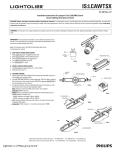
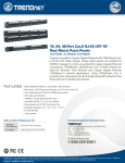
IS:LLACSW
Page 1 of 2
10-08/Rev-01
Installation Instructions for Surface LED
Colorwash Luminaire
CAUTION: Please read these instructions before installing the luminaire. To avoid electric shock, turn off the power from the electric panel before beginning. For safety, this
luminaire must be grounded. Consult an electrician to make sure all the requirements of the US or Canadian Code for electricity and the current local regulations comply. Keep these
instructions as reference.
Note 1: This portable luminaire (Fig.1) uses LED (light emitting diode lamps), which require no maintenance. Designed for residential, commercial and industrial applications, non
hazardous dry locations, ceiling (Fig.2), wall-mounted (Fig.3) and floor applications (Fig.4).
Note 2 : This portable luminaire includes a 96 in. extension cord and can also be hardwired using flexible metal conduit (Fig.5), two 3/8 in. connectors are supplied.
Portatif ColorWash
Ceiling
FIG.1
FIG.2
Wall
FIG.3a
A. OPTICAL ASSEMBLY ADJUSTMENT:
1. Adjust head on assembly at the desired angle. (Fig.6)
2. Lock in place inserting locking screws through hinge. (Fig.7)
Note: Use a 3/16 in. Allen key (not supplied).
B.
1.
1.
2.
3.
4.
5.
6.
CEILING or WALL MOUNT INSTALLATION: (Fig.2)
Note: Provide anchors to support 8 lb (3.6kg) luminaire.
For ceiling mount
Install 2 anchors at 20-1/2 in. (520mm) from luminaire center. (Fig.8)
Note: For more stability, install 4 anchors 2 in. from center of the luminaire.
(Fig.9)
For wall mount
Mount 2 anchors 15 in. (381mm) apart. (Fig.12)
Determine light beam orientation (uplight or downlight). (Fig.3a & 3b)
Loosen screw from the mounting tabs. (Fig.10 & 11)
Rotate and position oblong holes located at each end. (Fig.11)
Locate embossed holes and screw in place. (Fig.10 & 11)
Install screws (not provided) through oblong holes. (Fig.8 & 9)
FIG.3b
Floor
Daisy Chain
FIG.4
FIG.5
HEAD ON
HINGE
LOCKING
SCREW
FIG.6
FIG.7
ALLAN KEY
ANCHOR
LUMINAIRE
D. FLOOR INSTALLATION:
1. Position mounting tabs towards front of the luminaire (for stable floor standing),
or at each end. (Fig.10 & 11)
2. Loosen screw from the mounting tabs. (Fig.10 & 11)
3. For more stability depending on optical assembly orientation, secure with 2
screws from each end of assembly (optional). (Fig. 9 & 12)
4. Locate embossed holes and screw in place. (Fig.10 & 11)
5. Install screws through oblong holes. (Fig.12)
FIG.8
LUMINAIRE
EMBOSSED
HOLE
SCREW
MOUNTING
TAB
FIG.9
FIG.10
SCREW
MOUNTING TAB
Lightolier is a Philips group brand
FIG.11
IS:LLACSW
Page 2 of 2
E.
1.
2.
3.
4.
5.
6.
7.
8.
9.
10-08/Rev-01
DAISY CHAIN INSTALLATION: (Fig.13)
Note: Use 3/8 in. flexible metal conduit only.
Remove connection cover plate.
Loosen bushing and cord.
Remove knock-out from the large hole.
Note: For continuous daisy chain, other knock-out and cord
must be removed.
Insert red sleeve on BX cable.
Snap 3/8 in. connector into cover plate hole(s).
Connect the green wires to ground the fixture.
Connect the white (NEUTRAL) wires together.
Connect the black (120V) wires together.
Reinstall cover plate with 2 screws.
F. 4-BUTTON CONTROLLER:
Note: Control buttons display are touch-sensitive. Touch centre of pictogram. A
audible beep confirms new selection.
PRESET (
): (Fig. 14)
a) One-touch selection changes preset up or down .
b) Hold any selection to scroll between presets in a continuous loop hold preset
Note: For more details on PRESET, see PRESET sheet.
BRIGHTNESS (
/ ): (Fig.14)
a) One-touch selection increases/reduces brightness level by 5%.
b) Hold setting to dim up/down in 5% increments every 1/5 second.
G. FOR DMX CONTROL:
1. Simply connect data cable (shielded cats recommended) into DMX connector
RJ45e jack. (Fig.15)
2. For daisy chain data connection, connect data cable cat into data-in socket of
the first luminaire, then connect the data cable to the data-out connector jack of
the next luminaire and so on. (Fig.16)
3. For signal termination, connect a DMX signal terminator to the data out of the
last luminaire in the network. (sold separately). (Fig.17)
Note: Hardware required for DMX control system: (not supplied)
Controller: DMX512 protocol.
Wiring: Use low-capacitance shielded twisted-pair stranded cables such as
EIA485 (RS485) or shielded CAT#5e.
- 24AWG: maximum run length of 300 m (1000 ft).
- 22AWG: maximum run length of 500 m (1600 ft).
Note: Using unshielded cable may create noise in the system and may cause
undesirable light output.
Connectors: RJ45e connector – 8 conductors (connections: T568B).
SCREW
OBLONG HOLES
FIG.12
ANCHOR
COVER PLATE
SCREW
CORD
BUSHING
SLEEVE
CONNECTOR
BX
CABLE
FIG.13
PICTOGRAM
FIG.14
RECEPTACLE
RECEPTACLE
RJ45e
JACK
RJ45e
JACK
DATA-OUT
DATA-IN
FIG.16
FIG.15
DMX
TERMINATOR
Lightolier is a Philips group brand
FIG.17