1
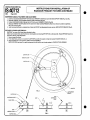
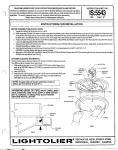
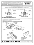
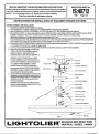
READ AND UNDERSTAND THESE INSTRUCTIONS BEFORE INSTALLING FIXTURE
‘hisfislure is intendedfor installationin accordanwwilh the NationalElectricalCodeendlocalregulations.
o assurefull compiianc$with localcadesandregulations,&e&with yourlocalelectricalinspectorbefore
!stallafion.To preventelectricalshock,turn off electricityat fuse box before proceeding,
Retain these instructions for maintenance reference.
INSTRUCTIONS
FOR
INSTALLATION
OF
RADIANCE
\
INSTRUCTION
PENDANT
SHEET
NO.
IS:40712
1292
Page 1 of 2
FIXTURES
FIXTUREASSEMBLYAND INSTALLATION:
1. CarefullyremoveCENTERSTEMASSEMBLY
frompacking.
2. Gently pull downward on CANOPY to disengaga from CROSSBAR SPRING CLIPS and axpose CROSSBAR,
3. Mount CROSSBAR and CENTER STEM ASSEMBLY to OUTLET BOX using OUTLET BOX SCREWS (provided with oullet box).
4. Adjust SWIVEL CASTING. For sloped miting appfication$ loosen UPPER LCCK NUT and turn SWIVEL CASTING until “U-SHAPED” opening in SWIVEL
is parallelto ceiling plane. This procedure can also be used t reorientation of SWIVEL CASTING is desired on non-sloped ceifings.
NOTE Fixture should only be mounted to mihngs having a maximum slope of 45” or less,
5. Make electrica connections black fixture lead or fixture lead without tracer marks to (hot) black supply lead; white fixture lead or fixture lead with trao?r mark
to (neutral) white supply lead. Uninsulated (bare) fixture wire isagmund and must be connected toa grounding terminal orwirein OUTLET BOX. Use WIRENUTS
(local hardware item). If supply wires are located witfin three inches of ballast, use wire rated for at least 90° C,
6. SldeCANOPY UPCENTERSTEM ASSEMBLY andallowSWIVELCASTING
topassthrough square opening in CANOPY. Push CANOPY upunti if fully engages
on CROSSBAR SPRING CLIPS and is sealed flush against ceiting,
7. Loosen and remove three BATTERY NUTS and STAR WASHERS from MOUNTING STUDS on LOWER FIXTURE ASSEMBLY,
8. Raise LOWER FIXTURE ASSEMBLY to MOUNTING
PLATE on CENTER STEM ASSEMBLY and make
electrica connections Snap together BLACK
CONNECTOR from LOWER FIXTURE ASSEMBLY tm
9.
9.
I
<>
9“17-<> 1.1 E m“ WRK’,!ww%ii%i
WTRlfCTfON SHEET NO.
INSTRUCTIONS FOR INSTALLATION OF
RADIANCE PENDANT FIXTURES CONTINUED
S:40712
!92
Page 2 of 2
JSPENSION CABLE Attachment
AND ADJUSTMENT
1. Loosen (do not remove) fhe BATTERY NUTS tha! secure WIREWAY COVERS on each of the three SUPPORT ARMS (Fig. 2 and 3A),
2, Slide each WIREWAY COVER inward towards the renter of the fixiure (Fig, 3A),
COVERS(Fig,3B},
3. Position SUSPENSION CABLES through the SLOTS in the end of WIREWAY
CABLEistau[,Securein position by tightening
4. SifdeeachWIREWAYCOVERoutwardfromthecanterofthefixiure untilSUSPENSION
BA~ERY NUTS (Fig. 3C).
5. Install recommended lamps by snapping base of lamp into SOCKET and allowing tip of lamp 10 rest on LAMP SUPPORT BRACKET (Fig, 2),
IFFUSER CLEANING AND REMOVAL
CAUTION Turn power off to fixture before anempting to dean.
needtobe
CMfuser can be cleaned from above the fixture by removing lamps and cleaning DIFFUSER with a soft damp cloth, Should DIFFUSER
removedforcleaning,followstepsbelow,
1. Removelampsfromfixlure,
2. Frombefowfixture,pushup on one side of the DIFFUSER and allow the opposite to drop down passed HOLOER KNOB (Fig. 1)
3. Side OIFFUSER out on an angle from LOWER FIXTURE ASSEMBLY
NOTEOIFFUSER
mayhaveFObegentlycompressed
oneitherside 10 pass through opening in LOWER FIXTURE ASSEMBLY.
SUPPORTARM
.-
WIREWAYCOVER
BA~ERY NUT
))
BATTERYNUT >
WIREWAYCOVER -J’
SUPPORTARM
B
/d
FfG.3