1
/
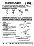
INSTRUCTION SHEET NO,
lS:1152-A
THIS REFLECTOR TRIM MUST BE INSTALLED
IN LIGHTOLIER’S
I102P1 FRAMEdN.KIT
WITH ROTO CLIPS
~W
■
Page 1 of 2
7,
READ AND UNDERSTAND
THESE lN~RUCTIONS
BEFORE
This fixture is intended for installation in accordance with the National
INSTALLING
FIXTURE.
Electrical Code and local regulations.
To assure full compliance
with local codes and regulations, check with your local electrical inspector before
installation. To prevent electrical shock, turn off electricity at fuse box before proceeding.
Retain these Instructions for mslntensnce refererrc-
%%E=
FIG. A
1. FRAME-fN
FIG, D
4. PUSH-UP
FIG. C
3. SNAPGN
FIG. B
2. ROTATE CLIPS
OF FIRE) DO NOT INSTALL lNSUIATfON
WARNING—(FilSK
WIRING COMPARTMENT,
WITHIN 3 INCHES OF FIXTURE SIDSS OR
NOR ABOVE FIXTURE IN SUCH A MANNER TO ENTRAP HSAT.
I
I
Zw%%%
1.
‘P
FRAME-fN (Fig. A)
See Frame-In-Kit Instruction
installation
procedure.
Sheets
IS-I 102, for
-<,,
sHORT LEG
ROTO-CLIP
(4 AROUND
‘“’ “G”
GREENFIELD
Y
TRIM lNSTALLATfON
3, Remove PINHOLE FACE PLATE from HOUSING by
inserting fingeta in aperture and pull apart fmm
HOUSING (Fig. G).
[
m
‘-/ \\_
.
-, ,;,w“...! .,,.’’:, . .
2. ROTATE ROTO-CLIPS @g. B)
.... .
q,
-.
Rotate (4) ROTO CLIPS so that the short legs extend
inwardly toward the center opening (Fig. F)
NOTE
The SHORT LEG of the ROTO CLIP hes NO
return on top. (Fig. E & F).
LONGLEG
SHORTLEG
‘@
\
*,,
,.,(.:;:. J..-,
=
0=/
-+
A:?
—
SPRING
G=
HOUSING
~u~Er
#’-I
MALEADAPTER
4. Insert HOOK in ear of SPRING
on SOCKfl
CUP and
let HOUSING hang down (Fig. H). Screw SOCKET
EXTENSION (MALE ADAPTER) into SOCK~
in
SOCKET CUR
./
q?
b404c~&G
~
5, oisengage
HOUSING
HOOK out of SPRING ear (Fig, G). Insert SOCKET CUP
between tabs on MOUNTING BRACKm making sure
SPRINGS snaps into slots of MOUNTING BRACKR
(Fig. c).
FIG. G
6, Tilt HOUSING md insert SOCKH CUP into ceiling
opening on side opposite junction box, pivot HOUSING
and push it up into ceiling until flange on HOUSING is
flush to ceiling (Fig, D).
‘m
,, ,’
---
s
HOU
U.S. PATENT NO. 4,&?S,%22,4,313,154and 4,32T,403
FOREIGN PATENTS PENDING,
SEE BACK FOR f.AMP lNSTALIATfON
B-1
AND ADJUSTMENT
C51”ITC>I-1
..-_..
FIYEH8?F,
ftom SOCKET CUP by pulling
IE
__..
..—–—
—
la”
iv;:;::i,N::;:::,E:iiT;:
INSTALLATION
OF LYTECASTER
REFLECTOR TRIM
IN THE 1102 FRAME-IN-KIT
WITH ROTO CLIPS
151152.A
0690
Page2 of 2
TRIM lNSTALLATtON(Contd)
INSULATING SLEEVING >
INSTALL LAMP
NmE
Sooket manufactures
have suggested
that socket may fall after 3 to 6 ralampinge. If
thla occurs sooket cart be replaced by
dlaconnectlng
male connectom (anached to
socket Ieada) from female connectors
(attached to flstura leads) and replacing it
with a socket procured through Lightoller,
see Fig. L
7. Remove
pulling
LAMP
straight
RING from IAMPNOKE
down (Fig. J),
HOLDER
-
/
“..
MA! F C.ONNHTCIRS
{At~aci;di;”50CGt-tik.,
FEMALE CONNECTORS
(Attached to Fixture WE.)
MR16 SOCKET
FIG. I
by
8. Insert LAMP (MR-16 Bulb) between LAMP SPRINGS
until face of bulb sits firmly on GLASS LAMP
GUARD (Fig. K).
““’’’K’v%
9. Attach SOCKET to hi-pin prungs on LAMP (Fig. K),
(NUIT% No polarity of pins required).
10. Insert LAMP RING with LAMP and GLASS LAMP
GUARD attached back into IAMPNOKE
HOLDER.
G
VERTICAUANGLE
ADJUSTMENT
AND LOCK
11. Insert a screwdriver into the LOCKING GUIDE on the
LAMPNOKE
HOLDER, and locate the slot in the
VERTICAL ADJUST/lQCK
SCREW. turn the SCREW.
~–
-’
FIG. J
counterclockwise+
and using the screwdriver as a ‘
lever, tilt the entire LAMP/’fOKE HOLDER to the
desired angle. Once the desired angle is reached,
tighten ecraw by turning screwdriver clockwise until
snug tight.
HORIZONTAL
ADJUST AND LOCK
12. The entire lAMP/YOKE
HOLDER can be horizontally
rotated to aim the angle of light through the hole in
the FACE PLATE TRIM (Fig. K). This can be done by
racking off the HORIZONTAL ADJUST/~CK
SCREW
one full turn freein
the SUPPORT PIATE (Fig. K).
Grasping the YOKE 8 on either side of the LAMPNOKE
HOLDER. rotate the SUPPORT PLATE to tha desired
angle, and lock the poeition by tightening” the
HORIZONTAL ADJUSWU3CK SCREW. Replete INSERTS
13, Insert PINHOLE
FACEPLATE,
RELAMPING The locking mechanism
rslock. Follow Steps 7-10 and 13,
in this fixture allow relamping without having to readjust and
NOTE 1. LOW VOLTAGE FIXTURES should be dimmed only with speciai dimmers intended
specifically for that purpose Use Lightolier Lytemodq Soeniat, Crsacendo VA, Neptune VA,
Precision VA, Easyaet VA, Sunrise VA, Radiant VA or equlvalant products by others or variabie
auto-transformera or eiactronic dimmers intendad for use with iow voltage fixtures. 2. Low
voitage fisturas may produce audibie sound whan usad with dlmmere which may be objectionai
in acouaticaiiy criticai areas.
WARNING:
Energizing
1. LAMP MANUFACWRES REQUiRE THE GLASS LAMP GUARD BE IN PLACE BEFORE
LAMR AND THAT GREAT CARE MUSr BE TAKEN THAT LAMP IS FULLY COOLED
BEFORE RELAMP!NG. AVOID FiNGER MARKS ON INSIDE OF LAMP FOR THEY MAY CAUSE SHORT
LAMP LIFE AND POSSIBLE BREAKAGE.
2. USE 0NL% REFLECIX)R “TRIMS PROViDED BY LiGHTOLIER INC. USE OF Uf’HER
MANUFA~URER’S
REFLECTOR TRiMS VOIDS THE UNDERWRITERS LABORA~RIES
LiSTING AND
‘ COULD Constitute
A FIRE HAZARD.
J
●