1
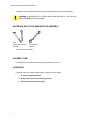
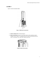
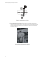
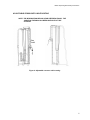
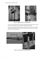
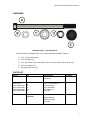
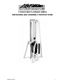
1 STACK MULTI-JUNGLE (SM10)
UNPACKING AND ASSEMBLY INSTRUCTIONS
M051-K50-A124
1
SM10 Unpacking & Assembly Instructions
The SM10 comes partially assembled. Follow the steps below to complete the assembly.
WARNING: COMPONENTS OF THE SM10 ARE LARGE AND HEAVY. USE CAUTION
WHEN ASSEMBLING THIS MACHINE.
MATERIALS AND TOOLS REQUIRED FOR ASSEMBLY
9/16”
Socket wrench with
extension
9/16”
Combination
wrench
You will also need a ladder.
ASSEMBLY TIME
Two people can accomplish this assembly in approximately 1/2 hour.
UNPACKING
Follow the steps below when unpacking the components of the SM10.
1. Cut off the shipping wrapper.
2. Remove the parts box and shipping boards.
3. Remove the items in the parts box.
2
SM10 Unpacking & Assembly Instructions
ASSEMBLY
Figure 1 shows an assembled SM10.
Figure 1. SM10 main components.
1. Place the weight cell in its final resting spot.
2. Bolt on the top tube using a 5/8” socket with extension and combination wrench
using two 7/16” x 5” bolts, 7/16” washers, and 7/16” nuts, end cap washers and end
caps. You may wish to use a pinch bar to align the bolt holes.
Figure 2. Bolt on the top tube.
3
SM10 Unpacking & Assembly Instructions
Figure 3. Configuration for 5” bolts.
3. Mount adjustable pulley bracket. When shipped, the adjustable pulley bracket
looks like the ones shown in Figure 4. The bolts need to be removed and the bracket
needs to be positioned so that the top of the bracket is in the top hole as shown by
the arrow in Figure 4.
Figure 4. Mount adjustable pulley bracket.
4
SM10 Unpacking & Assembly Instructions
ADJUSTABLE CROSSOVER CABLE ROUTING
NOTE: THE INFORMATION BELOW IS FOR REFERENCE ONLY. THE
CABLE ON THE SM10 HAS BEEN INSTALLED AT THE
FACTORY.
Figure 6. Adjustable crossover cable routing.
5
SM10 Unpacking & Assembly Instructions
Figure 7. Adjustable crossover cable end detail.
Using a 7/8” wrench, tighten the jam nut onto the adjustable pulley threads as shown in Figure
7. Place a rubber cap on the top of the cable as shown in Figure 7 (right).
Bolt the cable to the weight stacks as shown in Figure 8. Thread the 7/8” nut up on the cable
bolt as shown at left. Screw the bolt down into the weight stack as shown at right. Tighten the
bolt with a 7/8” combination wrench.
Figure 8. Screw the cable into the weight stack.
6
SM10 Unpacking & Assembly Instructions
HARDWARE
Hardware Figure 1. Assembly Parts.
The parts shown in Hardware Figure 1 are used to assemble the SM10. They are:
A. 7/16” x 5” hex head bolt (2)
B. 7/16” flat washer (2)
C. 7/16” cap washer (use on head end of the 6” bolt so end cap will fit on the nut) (2)
D. 7/16” hex head nut (2)
E. End caps (bolt covers) (2)
PARTS LIST
Part #
ID
Description
Quantity
1-stack cell
1
7/16” x 5” hex head bolt
7/16” flat washer
7/16” cap washer
7/16” Nyloc nut
End caps
2
2
2
2
2
Safety carabiner
Crossover handle
Leg strap
2
1
1
Main components
0017-001010017-00104-0363
0017-00104-0366
0017-00103-0233
0017-00042-0969
5” bolt hardware
A
B
C
D
E
Handle and bar
hardware
7