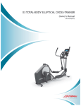
1
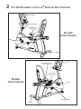
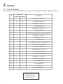
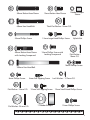
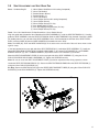
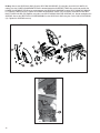
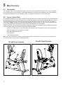
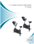
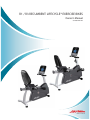
R1 / R3 RECUMBENT LIFECYCLE® EXERCISE BIKES
Owner’s Manual
8975001 REV B-2
CORPORATE HEADQUARTERS
5100 River Road
Schiller Park, Illinois 60176 • U.S.A.
847.288.3300 • FAX: 847.288.3703
Service phone number: 800.351.3737 (toll-free within U.S.A., Canada)
Global Website: www.lifefitness.com
INTERNATIONAL OFFICES
AMERICAS
North America
Life Fitness Inc.
5100 N River Road
Schiller Park, IL 60176 U.S.A
Telephone: (847) 288 3300
Fax: (847) 288 3703
Service Telephone: (800) 351 3737
Service Email: [email protected]
Sales/Marketing Email:
[email protected]
Operating Hours: 7:00 am-6:00 pm (CST)
Brazil
Life Fitness Brasil
Av. Cidade Jardim, 900
Jd. Paulistano
São Paulo, SP 01454-000
BRAZIL
SAC: 0800 773 8282
Telephone: +55 (11) 3095 5200
Fax: +55 (11) 3095 5201
Service Email: [email protected]
Sales/Marketing Email: [email protected]
Service Operating Hours:
9:00 - 17:00 (BRT) (Monday-Friday)
Store Operating Hours:
9:00 -20:00 (BRT) (Monday-Friday)
10:00 - 16:00 (BRT) (Saturday)
Latin America & Caribbean*
Life Fitness Inc.
5100 N River Road
Schiller Park, IL 60176 U.S.A
Telephone: (847) 288 3300
Fax: (847) 288 3703
Service Email: [email protected]
Sales/Marketing Email:[email protected]
Operating Hours: 7:00am-6:00pm (CST)
EUROPE, MIDDLE EAST, & AFRICA (EMEA)
Netherlands & Luxemburg
Life Fitness Atlantic BV
Bijdorpplein 25-31
2992 LB Barendrecht
THE NETHERLANDS
Telephone: (+31) 180 646 666
Fax: (+31) 180 646 699
Service Email: [email protected]
Sales/Marketing Email:
[email protected]
Operating Hours: 9.00h-17.00h (CET)
United Kingdom & Ireland
Life Fitness UK LTD
Queen Adelaide
Ely, Cambs, CB7 4UB
Telephone: General Office (+44) 1353.666017
Customer Support (+44) 1353.665507
Fax: (+44) 1353.666018
Service Email: [email protected]
Sales/Marketing Email: [email protected]
Operating Hours:
General Office: 9.00am - 5.00pm (GMT)
Customer Support: 8.30am - 5.00pm (GMT)
Germany & Switzerland
Life Fitness Europe GMBH
Siemensstraße 3
85716 Unterschleißheim
GERMANY
Telephone: (+49) 89.31 77 51.0 (Germany)
(+41) 0848 000 901 (Switzerland)
Fax: (+49) 89.31 77 51.99 (Germany)
(+41) 043 818 07 20 (Switzerland)
Service Email: [email protected]
Sales/Marketing Email: [email protected]
Operating Hours: 08.30 -16.30h (CET)
Austria
Life Fitness Austria
Vertriebs G.m.b.H.
Dückegasse 7-9/3/36
1220 Vienna
AUSTRIA
Telephone: (+43) 1.61.57.198
Fax: (+43) 1.61.57.198.20
Service Email: [email protected]
Marketing/Sales Email: [email protected]
Operating Hours: 08:30-16.30.h (MEZ)
Spain
Life Fitness IBERIA
C/Frederic Mompou 5,1º1ª
08960 Sant Just Desvern Barcelona
SPAIN
Telephone: (+34) 93.672.4660
Fax: (+34) 93.672.4670
Service Email: [email protected]
Sales/Marketing Email: [email protected]
Operating Hours:
9.00h-18.00h (Monday-Thursday)
8.30h-15.00h (Friday)
Belgium
Life Fitness Benelux NV
Parc Industrial de Petit-Rechain
4800 Verviers
BELGIUM
Telephone: (+32) 87 300 942
Fax: (+32) 87 300 943
Service Email: [email protected]
Sales/Marketing Email:
[email protected]
Operating Hours: 9.00h -17.00h (CET)
All Other EMEA countries &
Distributor Business C-EMEA*
Bijdorpplein 25-31
2992 LB Barendrecht
THE NETHERLANDS
Telephone: (+31) 180 646 644
Fax: (+31) 180 646 699
Service Email: [email protected]
Sales/Marketing Email:
[email protected]
Operating Hours: 9.00h-17.00h (CET)
ASIA PACIFIC (AP)
Japan
Life Fitness Japan
Nippon Brunswick Bldg., #8F
5-27-7 Sendagaya
Shibuya-Ku, Tokyo
Japan 151-0051
Telephone: (+81) 3.3359.4309
Fax: (+81) 3.3359.4307
Service Email: [email protected]
Sales/Marketing Email: [email protected]
Operating Hours: 9.00h-17.00h (JAPAN)
China and Hong Kong
Life Fitness Asia Pacific LTD
Room 2610, Miramar Tower
132 Nathan Road
Tsimshatsui, Kowloon
HONG KONG
Telephone: (+852) 2891.6677
Fax: (+852) 2575.6001
Service Email: [email protected]
Sales/Marketing Email: [email protected]
Operating Hours: 9.00h-18.00h
All Other Asia Pacific countries &
distributor business Asia Pacific*
Room 2610, Miramar Tower
132 Nathan Road
Tsimshatsui, Kowloon
HONG KONG
Telephone: (+852) 2891.6677
Fax: (+852) 2575.6001
Service Email: [email protected]
Sales/Marketing Email: [email protected]
Operating Hours: 9.00h-18.00h
Italy
Life Fitness Europe GmbH
Siemensstraße 3
85716 Unterschleißheim
GERMANY
Telephone: (+39) 02-55378611
Service: 800438836 (In Italy)
Fax: (+39) 02-55378699
Service Email: [email protected]
Sales/Marketing Email: [email protected]
Operating Hours: 08:30 - 16:30h (CET)
1
FCC Warning - Possible Radio / Television Interference
Note: This equipment has been tested and found to comply with the limits for a Class B digital device, pursuant to part
15 of the FCC rules. These limits are designed to provide reasonable protection against harmful interference in a residential installation. This equipment generates, uses and can radiate radio frequency energy, and if not installed and used
in accordance with the user manual, may cause harmful interference to radio communications. However, there is no
guarantee that the interference will not occur in a particular installation. If this equipment does cause harmful interference to radio or television reception, which can be determined by turning the equipment off and on, the user is encouraged to try to correct the interference by one or more of the following measures:
•
Reorient or relocate the receiving antenna.
•
Increase the separation between the equipment and the receiver.
•
Connect the equipment into an outlet on a circuit different from that to which the receiver is connected.
•
Consult the dealer or an experienced radio/TV technician for help.
Class HB (Home): Domestic use. Class B is not suitable for therapeutic purposes.
CAUTION: Any changes or modifications to this equipment could void the product warranty.
Any service, other than cleaning or user maintenance, must be performed by an authorized service representative.
There are no user-serviceable parts.
2
TABLE
OF
CONTENTS
1.
Important Safety Instructions . . . . . . . . . . . . . . . . . . . . . . . . . . . . . . . . . . . . . . . . . . . . . . . . . . . . . . . . . . .5
2.
R1 / R3 Recumbent Lifecycle® Exercise Bike Overview . . . . . . . . . . . . . . . . . . . . . . . . . . . . . . . . . . . . .7
3.
Assembly . . . . . . . . . . . . . . . . . . . . . . . . . . . . . . . . . . . . . . . . . . . . . . . . . . . . . . . . . . . . . . . . . . . . . . . . . .8
3.1
Tools & Hardware . . . . . . . . . . . . . . . . . . . . . . . . . . . . . . . . . . . . . . . . . . . . . . . . . . . . . . . . . . . . . . . . . . .8
3.2
Packaging . . . . . . . . . . . . . . . . . . . . . . . . . . . . . . . . . . . . . . . . . . . . . . . . . . . . . . . . . . . . . . . . . . . . . . . . .10
3.3
Assemble the Rear Stabilizer . . . . . . . . . . . . . . . . . . . . . . . . . . . . . . . . . . . . . . . . . . . . . . . . . . . . . . . . . .10
3.4
Secure Handlebar Assembly to Seat Assembly . . . . . . . . . . . . . . . . . . . . . . . . . . . . . . . . . . . . . . . . . . . .10
3.5
Seat Adjustment and Seat Back Pad . . . . . . . . . . . . . . . . . . . . . . . . . . . . . . . . . . . . . . . . . . . . . . . . . . . .11
3.6
Monocolumn, Wiring, and Cover . . . . . . . . . . . . . . . . . . . . . . . . . . . . . . . . . . . . . . . . . . . . . . . . . . . . . . .13
3.7
Attach Display Console . . . . . . . . . . . . . . . . . . . . . . . . . . . . . . . . . . . . . . . . . . . . . . . . . . . . . . . . . . . . . .14
3.8
Pedals . . . . . . . . . . . . . . . . . . . . . . . . . . . . . . . . . . . . . . . . . . . . . . . . . . . . . . . . . . . . . . . . . . . . . . . . . . . .15
3.9
R1 Water Bottle Holder and Bracket . . . . . . . . . . . . . . . . . . . . . . . . . . . . . . . . . . . . . . . . . . . . . . . . . . . .15
4.
Initial Setup . . . . . . . . . . . . . . . . . . . . . . . . . . . . . . . . . . . . . . . . . . . . . . . . . . . . . . . . . . . . . . . . . . . . . . . .16
5.
Main Features . . . . . . . . . . . . . . . . . . . . . . . . . . . . . . . . . . . . . . . . . . . . . . . . . . . . . . . . . . . . . . . . . . . . . .18
5.1
Accessories . . . . . . . . . . . . . . . . . . . . . . . . . . . . . . . . . . . . . . . . . . . . . . . . . . . . . . . . . . . . . . . . . . . . . . .18
5.2
Contact Heart Rate . . . . . . . . . . . . . . . . . . . . . . . . . . . . . . . . . . . . . . . . . . . . . . . . . . . . . . . . . . . . . . . . . .18
6.
Service and Product Maintenance
6.1
Troubleshooting . . . . . . . . . . . . . . . . . . . . . . . . . . . . . . . . . . . . . . . . . . . . . . . . . . . . . . . . . . . . . . . . . . . .19
6.2
Preventive Maintenance Tips . . . . . . . . . . . . . . . . . . . . . . . . . . . . . . . . . . . . . . . . . . . . . . . . . . . . . . . . . .21
6.3
Preventive Maintenance Schedule . . . . . . . . . . . . . . . . . . . . . . . . . . . . . . . . . . . . . . . . . . . . . . . . . . . . . .22
6.4.
How to Obtain Product Service . . . . . . . . . . . . . . . . . . . . . . . . . . . . . . . . . . . . . . . . . . . . . . . . . . . . . . . .22
7
Specifications . . . . . . . . . . . . . . . . . . . . . . . . . . . . . . . . . . . . . . . . . . . . . . . . . . . . . . . . . . . . . . . . . . . . . .23
8.
Warranty Information . . . . . . . . . . . . . . . . . . . . . . . . . . . . . . . . . . . . . . . . . . . . . . . . . . . . . . . . . . . . . . . .24
. . . . . . . . . . . . . . . . . . . . . . . . . . . . . . . . . . . . . . . . . . . . . . . . . . . . .19
© 2011 Life Fitness, a division of Brunswick Corporation. All rights reserved.
3
This Operation Manual describes the functions of the following product:
Life Fitness Recumbent Lifecycle® Exercise Bike Models:
R1 / R3
Thank you for purchasing a Life Fitness bike. Before using this product please read this user manual in its entirety to
ensure that you have the knowledge to safely and properly operate all of the features on your bike. We hope you
achieve the product experience on your bike that you expect, but if you do have any service issues please go to the
How to Obtain Product Service section which will provide information on obtaining domestic and international product
service. See Specifications in this manual for product specific features.
Statement of Purpose: The Life Fitness Lifecycle exercise bike is a machine that simulates the movements of riding a
bicycle at various speeds and levels of resistance.
CAUTION: Health-related injuries may result from incorrect or excessive use of exercise equipment. The
manufacturer STRONGLY recommends seeing a physician for a complete medical exam before undertaking an
exercise program, particularly if the user has a family history of high blood pressure or heart disease; or is over
the age of 45; or smokes, has high cholesterol, is obese, or has not exercised regularly in the past year. The
manufacturer also recommends consulting a fitness professional on the correct use of this product.
If, at any time while exercising, the user experiences faintness, dizziness, pain, or shortness of breath, he or
she must stop immediately.
4
1
IMPORTANT SAFETY INSTRUCTIONS
WARNING: Read all instructions before using the Life Fitness Lifecycle exercise bike. Save these Instructions.
WARNING: Heart rate monitoring systems may be inaccurate. Over exercising may result in serious injury or death.If
you feel faint stop exercising immediately.
DANGER: To reduce the risk of electrical shock, always unplug this Life Fitness product before cleaning or attempting
any maintenance activity.
SAFETY WARNING: The safety of the product can be maintained only if it is examined regularly for
damage and wear. See Preventive Maintenance section for details.
The heart rate hand pulse sensors provide an approximate heart rate value. The sensors are not medical
devices and should not be used in any type of medical application.
•
Before using this product, it is essential to read this ENTIRE operation manual and ALL instructions. The
exercise bike is intended for use solely in the manner described in this manual.
•
Always follow the console instructions for proper operation.
•
This appliance is not intended for use by persons (including children) with reduced physical, sensory or mental
capabilities, or lack of experience and knowledge, unless they have been given supervision or instruction concerning use of the appliance by a person responsible for their safety.
•
Children should be supervised to ensure that they do not play with the appliance.
•
Never insert objects into any openings in this product. If an object should drop inside, turn off the power, unplug
the power cord from the outlet and carefully retrieve it. If the item cannot be reached, contact Life Fitness
Customer Support Services.
•
Never place liquids of any type directly on the unit, except in an accessory tray. Containers with lids are
recommended.
•
Do not use the exercise bike outdoors, near swimming pools or in areas of high humidity.
•
Keep all loose clothing, shoelaces, and towels away from the bike pedals.
•
Keep the area around the Lifecycle clear of any obstructions, including walls and furniture.
•
Use caution when mounting or dismounting the Lifecycle.
•
Never operate a Life Fitness product if it has been dropped, damaged, or even partially immersed in water.
Contact Life Fitness Customer Support Services.
•
Keep the power cord away from heated surfaces. Do not pull the equipment by the power cord or use the power
cord as a handle.
•
Do not run the power cord on the floor under or along side of the Lifecycle.
•
Wear shoes with rubber or high-traction soles. Do not use shoes with heels, leather soles, cleats or spikes. Do
not use the Lifecycle in bare feet.
•
Do not tip the Lifecycle on its side during operation.
•
Keep hands and feet away from all moving parts.
•
To ensure proper functioning of this product, do not install attachments or accessories that are not provided or
recommended by Life Fitness.
5
•
Use this product in a well-ventilated area.
•
Use this product on a solid, level surface.
•
Make sure that all components are fastened securely.
•
An appliance should never be left unattended when plugged in. Unplug from outlet when not in use, and before
putting on or taking off parts.
•
Do not operate under blanket or pillow. Excessive heating can occur and cause fire, electric shock, or injury to
persons.
•
Never operate this appliance if it has a damaged cord or plug, if it is not working properly, if it has been dropped
or damaged, or dropped into water. Contact Life Fitness Customer Support Services.
•
Never operate the appliance with the air openings blocked. Keep the air openings free of lint, hair, and the like.
•
To disconnect, turn all controls to the off position, then remove plug from outlet.
•
Allow LCD consoles to “normalize” with respect to temperature for one hour before plugging the unit in and/or
using.
SAVE THESE INSTRUCTIONS FOR HOUSEHOLD USE.
6
2
R1 / R3 RECUMBENT LIFECYCLE® EXERCISE BIKE OVERVIEW
Console
Water Bottle Holder
Contact Heart
Rate Sensors
R1 with
Track Console
Pedal
Leveler
Water Bottle Holder /
Accessory Tray
Console
Contact Heart
Rate Sensors
R3 with
Track Console
Pedal
Seat Adjustment
Leveler
7
3
ASSEMBLY
3.1
TOOLS & HARDWARE
Identify the following components after unpacking your Lifecycle. The tools needed for assembling the product are included.
Quantity
Item
Description
R1
R3
1
2
2
50mm Button Head Screw
2
10
10
15mm Button Head Screw
3
5
5
Flat Washer - 18mm O.D.
4
8
4
55mm Phillips Screw
5
8
4
Lock Washer - 12.2mm O.D.
6
0
4
8mm Phillips Screw
7
1
1
40mm Button Head Screw with Locking Compound
8
1
1
Flat Washer - 24mm O.D.
9
1
1
Rubber Bumper Insert
10
1
1
1” Rubber Bumper
11
2
2
12mm Phillips Screw with Locking Compound
12
2
2
12mm Large Head Phillips Screw
13
2
2
100mm Hex Head Bolt
14
5
5
Thick Flat Washer - 16mm O.D.
15
2
2
60mm Hex Head Bolt
16
6
4
12mm Small Head Phillips Screw
17
4
4
Flat Washer - 12mm O.D.
18
4
4
12mm Self-Tapping Screw
19
0
4
12mm Phillips Screw
20
0
4
16mm Phillips Screw
21
0
4
Nylock Nut
22
0
4
8mm Self-Tapping Screw
Tools Needed for Assembly:
• Metric Wrench Set
• Metric Allen Wrench Set
• Phillips Screwdriver
8
50mm Button Head Screw
15mm Button Head Screw
Thick Flat Washer -16mm O.D.
60mm Hex Head Bolt
55mm Phillips Screw
12mm Large Head Phillips Screw
12mm Phillips Screw with
Locking Compound
40mm Button Head Screw
with Locking Compound
8mm Self-Tapping Screw
Flat Washer -12mm O.D.
10
20
30
12mm Small Head Phillips Screw
12mm Phillips Screw
1” Rubber Bumper
40
50
Flat Washer 18mm O.D.
Lock Washer - 12.2mm O.D.
12mm Self-Tapping Screw
Flat Washer -24 mm O.D.
Nylock Nut
16mm Phillips Screw
100mm Hex Head Bolt
8mm Phillips Screw
Rubber Bumper
Sleeve
60
70
80
90
100
110
120
130
140
150
160
9
3.2
PACKAGING
Parts: None
Remove all packaging and place main components to the side of the box. Break box down in each of the four corners.
3.3
ASSEMBLE
THE
REAR STABILIZER
Parts: Hardware Bag #1
(2, 50mm Button Head Screws)
(2, 15mm Button Head Screws)
Tools: 5mm Hex Head Wrench
Locate and install the two LEVELER FEET (A) to the bottom of the REAR STABILIZER (B).With the bends facing rearward, attach the REAR STABILIZER (B) to the
BASE UNIT (C) using two 50mm BUTTON HEAD SCREWS (1) from the top of the
REAR STABILIZER BRACKET (D) and two 15mm BUTTON HEAD SCREWS (2)
from the front side of the REAR STABILIZER BRACKET. Tighten the SCREWS
securely.
3.4
SECURE HANDLEBAR ASSEMBLY TO SEAT ASSEMBLY
Parts: Hardware Bag #2
(4,
(4,
(4,
(4,
(4,
(4,
15mm Hex Head Bolts)
55mm Phillips Screws) R1 Only
Lock Washers)
16mm Phillips Screws) R3 Only
8mm Phillips Screws) R3 Only
18mm O.D. Flat Washers)
Tools: 5mm Hex Head Wrench, Phillips Screwdriver
Locate the HANDLEBAR ASSEMBLY (E) and the SEAT ASSEMBLY (F). With the handlebars facing upward and forward, align the mounting holes of the HANDLEBAR ASSEMBLY with those in the SEAT ASSEMBLY. Secure the HANDLEBAR ASSEMBLY to the SEAT ASSEMBLY using four 15mm BUTTON HEAD SCREWS (2) and FLAT WASHERS
(3). Tighten the SCREWS securely. Connect the CONNECTOR (G) leading from the HANDLEBAR ASSEMBLY (E) with
the CONNECTOR (G) leading from the SEAT ASSEMBLY (F). Be sure the connectors fully lock.
R1 Only: Locate the SEAT BOTTOM (H). Align the SEAT BOTTOM mounting holes with those in the LOWER SEAT
SUPPORTS (J). Secure the SEAT BOTTOM using four 55mm PHILLIPS SCREWS (4) and LOCK WASHERS (5).
Tighten the SCREWS securely.
R3 Only: Locate the SEAT BOTTOM (H). Align the SEAT BOTTOM mounting holes with those in the LOWER SEAT
SUPPORTS (J). Secure the SEAT BOTTOM using four 16mm PHILLIPS SCREWS (20) and LOCK WASHERS (5).
Tighten the SCREWS securely. Locate the ACCESSORY TRAY (K). Secure the ACCESSORY TRAY to the HANDLEBAR ASSEMBLY using four 8mm PHILLIPS SCREWS (6) as shown. Tighten the SCREWS securely.
R1
10
R3
3.5
SEAT ADJUSTMENT AND SEAT BACK PAD
Parts: Hardware Bag #3
(1,
(1,
(1,
(1,
(1,
(2,
(2,
(4,
(4,
(4,
(4,
40mm Button Head Screw with Locking Compound)
24mm Flat Washer)
Rubber Bumper Sleeve)
Rubber Bumper 1”)
18mm Flat Washer)
12mm Phillips Screws with Locking Compound)
12mm Phillips Screws)
55mm Phillips Screws) R1 Only
8mm Nylock Nuts) R3 Only
8mm Self-Tapping Phillips Screws) R3 Only
12mm Phillips Screws) R3 Only
Tools: 5mm Hex Head Wrench, Phillips Screwdriver, 13mm Socket Wrench
Align the guide rollers located on the underside of the SEAT ASSEMBLY (F) with the SEAT EXTRUSION (L). Carefully
guide the SEAT ASSEMBLY onto the SEAT EXTRUSION. Slide the SEAT ASSEMBLY fully forward. Connect the WIRE
(M) leading from the user left side of the SEAT ASSEMBLY to the JACK located at the left front of the SEAT EXTRUSION. Insert the WIRE (M) into the WIRE HARNESS (N) located next to the JACK.
Note: The WIRE (M), JACK and WIRE HARNESS (N) are located on the user left side of the unit. Items shown on the
right for clarity.
In the hole located on the user right side of the SEAT EXTRUSION (L), behind the SEAT ASSEMBLY (F), install one
40mm BUTTON HEAD SCREW WITH LOCKING COMPOUND (7), one 24mm FLAT WASHER (8), one RUBBER
BUMPER SLEEVE (9), one 1" RUBBER BUMPER (10) and one 18mm FLAT WASHER (3) as shown.
Mount the SEAT ADJUSTMENT LEVER (O) to the user right side of the SEAT ASSEMBLY (F) using two 12 mm
PHILLIPS SCREWS W/LOCKING COMPOUND (11). Tighten the SCREWS securely.
Note: Be sure to mount the SEAT ADJUSTMENT LEVER (O) with the adjustment knob facing upward as shown.
Locate the SEAT EXTRUSION ENDCAP (P). Secure the SEAT EXTRUSION ENDCAP to the SEAT EXTRUSION (L)
using two 12mm PHILLIPS SCREWS (12).
R1 Only: Secure the SEAT BACK PAD (Q) to the UPPER SEAT SUPPORT TUBES (R) using four 55mm PHILLIPS
SCREWS (4) and LOCK WASHERS (5). Tighten the SCREWS securely.
R1
11
R3 Only: Secure the SEAT BACK PAD (Q) to the SEAT BACK SUPPORT (R) using four 8mm NYLOCK NUTS (21)
making sure the LOWER ADJUSTMENT STRAP is located behind the SUPPORT TUBES. Be careful not to allow the
LOWER ADJUSTMENT STRAP to be caught between the SEAT BACK SUPPORT and the SEAT MOUNTING BRACKET. Tighten the NUTS securely. Tighten the LOWER ADJUSTMENT STRAP (OO) as shown. Assemble the two SEAT
BACK COVER HALVES (PP) together using four 8mm SELF-TAPPING PHILLIPS SCREWS (22). Do not overtighten the
SCREWS. Secure the SEAT BACK COVER ASSEMBLY to the SEAT BACK PAD using four 12mm PHILLIPS SCREWS
(19). Tighten the SCREWS securely.
R3
12
3.6
MONOCOLUMN, WIRING AND COVER
Parts: Hardware Bag #4
(2, 100mm Hex Head Bolts)
(5, Thick Flat Washers - 16mm O.D.)
(2, 60mm Hex Head Bolts)
(4, 12mm Phillips Screws)
(4, Flat Washers - 12mm O.D.)
(4, 15mm Button Head Screws)
Tools: 13mm Socket Wrench, 5mm Hex Head Wrench, Phillips Screwdriver
Locate the MONOCOLUMN (S). Slide the MONOCOLUMN COVER (T) onto the MONOCOLUMN as shown. Slide the
MONOCOLUMN COVER up to the FRONT HANDLEBAR POSTS (U).
Note: A zip-tie has been included to keep the MONOCOLUMN COVER (T) from falling during assembly.
Detach the WIRE TIE (V) attached to the front of the MONOCOLUMN (S). Carefully pull the CONSOLE WIRE (W)
through the SIDE ACCESS HOLE (X) of the MONOCOLUMN. Feed the CONSOLE WIRE through the GROMMET (Y)
as shown and insert the GROMMET into the SIDE ACCESS HOLE. Slide the MONOCOLUMN (S) into the MONOCOLUMN BRACKET (Z). Slide the MONOCOLUMN down until it is fully seated. Secure the MONOCOLUMN to the MONOCOLUMN BRACKET using two 100mm HEX HEAD BOLTS (13) and three THICK FLAT WASHERS (14) from the front
side of the MONOCOLUMN and two 60mm HEX HEAD BOLTS (15) and THICK FLAT WASHERS (14) from the user left
side of the MONOCOLUMN BRACKET. Tighten the BOLTS securely.
Note: The two 100mm HEX HEAD BOLTS (13) and three
THICK FLAT WASHERS (14) are shown entering from the back
side of the MONOCOLUMN for clarity. Please secure from the
FRONT side.
CAUTION: Be careful not to pinch the WIRE(s) (AA) leading
from the MONOCOLUMN BRACKET (Z) when inserting the
MONOCOLUMN (S) into the MONOCOLUMN BRACKET.
Connect the WIRE(s) (AA) leading from the MONOCOLUMN
BRACKET (Z) to the corresponding WIRE (W) from the SIDE
ACCESS HOLE (X) of the MONOCOLUMN. Slide the MONOCOLUMN COVER (T) downward to meet the MAIN SHROUDS.
Secure the MONOCOLUMN COVER to the MAIN SHROUDS
using four 12mm PHILLIPS SCREWS (16) and four 12mm O.D.
WASHERS (17). Tighten the SCREWS securely. Do not overtighten the SCREWS.
Attach the RIGHT (BB) and LEFT (CC) FRONT HANDLEBARS
(labeled right and left) to the MONOCOLUMN as shown using
two each 15mm BUTTON HEAD SCREWS (2). Tighten the
SCREWS securely
13
3.7
ATTACH DISPLAY CONSOLE
Parts: Hardware Bag #5
(4, 12mm Phillips Screws)
Tools: Phillips Screwdriver
Remove the DISPLAY CONSOLE (DD) from its shipping carton. Position the DISPLAY CONSOLE above the DISPLAY
CONSOLE BRACKET (EE). Connect the CONSOLE WIRE 15-pin connector (FF), HEART RATE WIRE 4-pin connector
(GG), SUPPLEMENTAL POWER WIRE 2-pin connector (OO), and GROUND WIRE single spade (HH) (Green) to the
corresponding CONNECTORS located on the back of the DISPLAY CONSOLE. Secure the DISPLAY CONSOLE to the
DISPLAY CONSOLE BRACKET using four 12mm PHILLIPS SCREWS (18). Tighten the SCREWS securely. Do not
overtighten the SCREWS.
HH
18
OO
DD
FF
GG
EE
Track Console Connections
FF
Go Console Connections
OO
FF
HH
OO
HH
GG
14
GG
3.8
PEDALS
Tools: 15mm Open End Wrench
Locate the RIGHT PEDAL (JJ) (marked with an "R") and PEDAL STRAP (KK)
(marked with an "R"). With the side of the PEDAL STRAP marked with an “R” facing upward, slide the slotted end of the PEDAL STRAP through the left slot in the
PEDAL. Fasten one of the slots onto the tab located under the left slot of the
PEDAL. Bend the PEDAL STRAP upward and slide the remaining end of the
PEDAL STRAP through the right slot in the PEDAL and into the strap adjustment
clip. The PEDAL STRAP should securely engage the strap adjustment clip.
Install the RIGHT PEDAL (JJ) to the USER RIGHT CRANK ARM (LL).
Repeat for the LEFT PEDAL (marked with an "L") and PEDAL STRAP (marked
with an "L").
Note: The LEFT PEDAL has reverse threads.
Note: Pedals need to be securely tightened or clicking may occur.
3.9
R1 WATER BOTTLE HOLDER & BRACKET
Parts: Hardware Bag #4
(2, 12mm Phillips Screws)
Tools: Phillips Screwdriver
Locate the WATER BOTTLE BRACKET (MM). Secure the WATER BOTTLE BRACKET to the underside of the MONOCOLUMN (S) using two 12mm PHILLIPS SCREWS (12). Tighten the SCREWS securely. Insert the WATER BOTTLE
(NN) into the WATER BOTTLE BRACKET.
15
4
INITIAL SETUP
Read the entire User Manual before setting up the Lifecycle exercise bike.
WHERE
TO
PLACE
THE
EXERCISE BIKE
Following all safety instructions in Section 1 move the bike to the location in which it will be used. See Section 7,
Specifications, for the dimensions of the footprint. Allow a distance of 4 feet (120 centimeters) between the bike and
other objects or surfaces on either side.
HOW
TO
STABILIZE
THE
EXERCISE BIKE
After placing the bike in position, check the unit's stability by attempting to rock it
in all directions. Any slight rocking indicates that the unit must be leveled.
Determine which foot is not resting completely on the floor. Loosen the jam nut
with an open-end 17mm wrench, and rotate the stabilizing foot to lower it. Verify
that the bike is stable, and repeat the adjustment as necessary until the unit no
longer rocks. Lock the adjustment by tightening the jam nut against the stabilizer
bar.
HOW
TO
ADJUST
THE
SEAT
TO
ENSURE CORRECT BIOMECHANICAL POSITIONING
Proper seat positioning minimizes unnecessary leg muscle fatigue. To determine whether or not the seat requires adjustment, sit on it and place the balls of the feet on the pedals. The knee should bend slightly when the pedal is at the furthest
point in its rotation, relative to the body. The user should be able to pedal without locking the knees or shifting in the seat.
Adjusting the seat: Lift the spring-loaded adjusting handle (A) located on the right side of the seat. Slide the seat forward or backward as necessary to the proper position and release the pin to complete engagement. Gently rock the seat
forward and backward to ensure that it is locked into place. Check the seat distance again and readjust it if necessary.
Note: If the seat carriage rocks excessively, use a wrench to loosen the jam nut (A) on either side of the seat carriage.
With another wrench, tighten the adjustment roller on the inside of the carriage until it is snug, but do not overtighten it.
Then, while holding the roller in place, tighten the lock nut. Repeat the procedure for the other side of the seat carriage.
CAUTION: Do not attempt to adjust the seat while pedaling the bike. Doing so, or failing to insert the seat pin completely, may result in an uncomfortable workout or cause injury.
16
HOW
TO
ADJUST
THE
PEDAL STRAPS
The bike pedal safety straps keep the user's shoes on the pedals during a
workout. The straps should fit comfortably, but they also should be tight
enough to prevent shoes from slipping at any point in the pedaling rotation.
Before working out, the user should test and adjust the tightness of the
straps.
The straps can be adjusted to fit a variety of shoe sizes. Each strap is held
in place by a spring-loaded clip that is connected to the outer edge of each
pedal. To tighten a strap, simply pull the loose end of the strap down. It automatically locks into place with each pull. To loosen a strap, press down on
the top of the clip and pull the strap up. Release the clip to lock the strap
into place. Test the adjustment, and change if necessary.
HOW
TO
ADJUST
THE
SEAT BACK (R3 ONLY)
The R3 has an adjustable seat back so you can choose the most comfortable back angle for your workout. To adjust the
seat back, pull the lever (A) towards the rear of the bike. While pulling the lever, lean backwards or forwards. Once you
reach a comfortable position, release the lever and the seat back will lock in place.
A
STARTING UP THE BIKE
See Section 7, Specifications, for power requirements. Insert the AC adapter into an electrical outlet that has been properly installed and grounded in accordance with all local codes and ordinances.
Insert the power adapter jack into the barrel plug on the bottom of the exercise bike. Then insert the power supply into
the wall outlet. Make sure the cord is routed so that it doesn't bind and will not be walked on.
Check that the console lights up. If not, recheck the plug and wall connections and make sure the wall outlet has power.
Once the unit’s power is on, the console display lights up, making it possible to select a workout. When using a self-powered unit, start pedaling to light up the console.
Note: For customers outside the United States, please use your country specific transformer to power the unit.
Note: The R3 can be self-powered if using a Go Console. The PAUSE time is limited to 30 seconds. Workout data will
be cleared after 30 seconds of inactivity. Extend the PAUSE time by plugging the power supply in to the Go Console.
17
5
MAIN FEATURES
5.1
ACCESSORIES
Two accessory trays (A) are mounted to the right of the seat on the R3 to provide storage for items such as water bottles, personal stereos, and cell phones. A Water Bottle Holder (B) is located on the monocolumn of the R1. Additionally,
an integrated Reading Rack (C) for supporting a book or magazine is located at the base of the console.
5.2
CONTACT HEART RATE
The hand pulse sensors (D) are a built-in heart rate monitoring system on the stationary handlebar. During a workout grasp
the hand pulse sensors to monitor your heart rate. We recommend using the heart rate chest strap provided with your console during workouts and using the hand pulse sensors to only occasionally monitor your heart rate when not using the
chest strap. In addition, to utilize heart rate controlled workouts the chest strap must be used. For the most accurate reading, use a comfortable grip. The console will show a heart rate reading after 15 to 20 seconds.
Hand pulse sensors can work differently with different body types. With some individuals it can be very difficult to extract a
heart rate reading. Follow the below tips to improve the heart rate reading.
·
Remove your hands from the heart rate sensors and wait for the heart rate display to clear. Grasp sensors again.
·
Make sure hands are fully contacting the sensors.
·
Dry hands periodically during use.
·
Limit movement.
·
Clean hand pulse sensors.
Note: The heart rate hand pulse sensors provide an approximate heart rate value. The sensors are not medical devices
and should not be used in any type of medical application.
R1 with Track Console
R3 with Track Console
C
C
D
B
D
A
18
6
SERVICE & PRODUCT MAINTENANCE
6.1
TROUBLESHOOTING
Problem
Cause / Solution
Check to see that the power cord is fully plugged into the back of the
Lifecycle exercise bike and into the wall. Make sure the power cord is fully
seated into the back of the Lifecycle exercise bike.
No power.
You may be in “Energy Saver Mode”. Press the “Energy Saver” button to
see if the console turns on.
Verify that all customer assembly connections are working properly.
Unplug and re-plug each connection to verify. Look to see if any cables
were pinched during assembly.
Clicking noise while pedaling.
Use the wrench that was included with the Lifecycle exercise bike to
ensure the pedals are assembled as tight as possible.
Hear noise as speed increases.
It is normal for any mechanical device to become louder as speed
increases.
Can’t feel a resistance change at the
beginning levels.
The resistance curve of the Lifecycle exercise bike is designed so that
you can feel a greater difference in resistance at higher levels.
Potential reasons for the wireless heart rate not to work properly include:
1.
2.
Wireless heart rate is not working.
3.
4.
The wireless heart rate is turned OFF in the Settings Menu. Enter
the Settings Menu and verify that WIRELESS HR is turned ON.
There is poor contact between the telemetry heart rate strap and
the skin.
There is electrical interference from electrical appliances with the
telemetry heart rate strap from fluorescent lights, kitchen appliances,
etc. Move the Lifecycle exercise bike to a different location or move
electrical appliances away from the Lifecycle exercise bike.
The battery in the Heart Rate Telemetry Strap needs to be replaced.
The battery is a CR2032 (3V).
19
Problem
“OFF” is displayed in the LEVEL
window on the console.
Contact heart rate sensors are
not reading my heart rate correctly.
Cause / Solution
Turn the unit off and then on again.
If power cycling the product did not work, there is a problem with the
resistance system. Contact Customer Support Services for assistance.
Be sure to grasp the sensors firmly and keep hands still. If heart rate
seems substantially higher or lower than expected, remove hands from
sensors until heart rate disappears.
Tips for contact heart rate:
1. Dry hands to prevent slipping on the sensors.
2. Apply hands to all four sensors (two in each hand).
3. Grasp sensors firmly.
4. Apply constant pressure to the sensors.
5. May need to wait longer for heart rate to display.
Note: The heart rate hand pulse sensors provide an approximate heart
rate value. The sensors are not medical devices and should not be used
in any type of medical application.
Seat wobbles.
The seat carriage can be adjusted if it is too tight and does not slide
freely or if it is too loose and rocks excessively.
Use a wrench to loosen the jam nut on either side of the seat carriage to
adjust the fit of the carriage when there is excessive rocking. With another wrench, tighten the adjustment roller on the inside of the carriage until
it is snug. Do not overtighten. Then, while holding the roller in place,
tighten the lock nut. Repeat the procedure for the other side of the carriage.
Use a wrench to loosen the jam nut on either side of the seat carriage to
adjust the fit of the carriage when it does not slide freely. With another
wrench, loosen the adjustment roller on the inside of the carriage until it
can move freely. Do not excessively loosen. Then, while holding the
roller in place, tighten the lock nut. Repeat the procedure for the other
side of the carriage.
The mesh back material is loose.
The straps that hold the seat mesh to the seat frame must be tightened.
Use a Phillips screwdriver to remove the four screws that hold the rear
plastic seat cover in place. Determine which straps are loose. Remove
the loose end of the strap going through the tension clip loop. To tighten
the strap, pull it in the opposite direction of the clip loop. Tension all
straps as needed. Reinstall the rear plastic seat cover.
iPod is not recognized.
Note: Applies to Track Console only.
iPod is not charging while in Energy
Saver mode.
Note: Applies to Track Console only.
”Low Battery” message is displayed
on the console.
Note: Applies to Track Console only.
When I try to save a workout on the
USB stick I receive the following
message: UNABLE TO SAVE SEE
MANUAL.
Note: Applies to Track Console only.
20
This is displayed if your version of the iPod Player is not supported by
the bike.
It may also be displayed if the connector on the bike or iPod is damaged.
Your iPod will not charge if the bike enters Energy Saver mode. This is
normal.
The console has an internal battery that keeps the real time clock
functioning if the bike is unplugged. This real time clock is only needed if
you use the Life Fitness ”Virtual Trainer” website. You do not need to
replace the battery if you do not use the website. Contact Customer
Service for guidance on how to change the battery. The battery is a
CR1632 (3V).
The console may not have recognized the USB stick. Try unplugging the
USB stick and plugging it back in.
The USB stick may be full.
The USB stick may not be compatible with the product.
Try using a different USB stick.
6.2
PREVENTIVE MAINTENANCE TIPS
The Life Fitness Lifecycle exercise bike is backed by the engineering excellence and reliability of Life Fitness and is one
of the most rugged and trouble-free pieces of exercise equipment on the market today.
Note: Safety of the equipment can be maintained only if the equipment is examined regularly for damage or wear. Keep
the equipment out of use until the defective parts are required or replaced. Pay special attention to parts that are subject
to wear, as outlined below.
The following preventive maintenance tips will keep the Life Fitness exercise bike operating at peak performance:
•
Locate the Life Fitness Bike in a cool, dry place.
•
Keep the pedal straps fastened securely when using the Bike.
•
Clean the top surface of the pedals regularly.
•
Keep the display console free of fingerprints and salt build-up caused by sweat.
•
Clean the display console and all exterior surfaces with an approved or compatible cleaner (see Life Fitness
Approved Cleaners) and a soft cotton cloth.
•
Long fingernails may damage or scratch the surface of the console; use the pad of the finger to press the selection buttons on the console.
•
Clean the housing thoroughly on a regular basis.
LIFE FITNESS APPROVED CLEANERS
Two preferred cleaners have been approved by Life Fitness reliability experts: PureGreen 24 and Gym Wipes. Both
cleaners will safely and effectively remove dirt, grime and sweat from equipment. PureGreen 24 and the Antibacterial
Force formula of Gym Wipes are both disinfectants that are effective against MRSA and H1N1.
PureGreen 24 is available in a convenient spray. Apply the spray to a microfiber cloth and wipe down the equipment.
Use PureGreen 24 on the equipment for at least 2 minutes for general disinfection purposes and at least 10 minutes for
fungus and viral control. Gym Wipes are large, durable pre-moistened wipes to use on the equipment before and after
workouts. Use Gym Wipes on the equipment for at least 2 minutes for general disinfection purposes.
Contact Life Fitness Customer Support Services to order these cleaners.
Call 1-800-351-3737 or email: [email protected].
LIFE FITNESS COMPATIBLE CLEANERS
Mild soap and water or a mild non-abrasive household cleaner can also be used to clean the display and all exterior surfaces. Use a soft cotton cloth only. Apply the cleaner to the cotton cloth before cleaning. DO NOT use ammonia or acid
based cleaners. DO NOT use abrasive cleaners. DO NOT use paper towels. DO NOT apply cleaners directly to the
equipment surfaces.
21
6.3
PREVENTIVE MAINTENANCE SCHEDULE
ITEM
WEEKLY
Console Overlay
Clean
Bottle Holders
Clean
MONTHLY
Inspect
Inspect
Console Mounting Bolts
6.4
BI-ANNUALLY
Inspect
Frame
Clean
Plastic Covers
Clean
Lifepulse Sensors
Clean / Inspect
Pedals and Straps
Clean
Inspect
Inspect
Inspect
Inspect
HOW TO OBTAIN PRODUCT SERVICE
1. Please contact your dealer or Life Fitness Customer Service at 1-800-351-3737.
2. Verify the symptom and review the operating instructions and troubleshooting matrix.
3. Locate and document the serial number of the unit. The serial number plate is located on the front stabilizer, below the
shroud. Please also have proof of purchase information available.
22
7
SPECIFICATIONS
LIFE FITNESS R1 / R3 RECUMBENT LIFECYCLE® EXERCISE BIKES
Designed Use:
Home
Max User Weight:
300 lbs. / 136 kg. (R1)
400 lbs. / 181 kg. (R3)
Pedal Size:
4.5 in. / 11.5 cm.
Drive Type:
Poly -V belt-drive
Power Requirements:
120 Volt (U.S.), 220 Volt (Europe), 240+ Volt (Australia)
Note: The R3 can be self-powered with the Go Console.
Accessories:
Water Bottle Holder & Reading Rack (R1)
Two Accessory Trays & Reading Rack (R3)
Resistance System:
Eddy Current (R1)
Generator (R3)
Note: Both resistance systems are speed independent.
Assembled Dimensions
Length
Width
Height
Weight
R1
56.5 in. / 143.5 cm.
25.75 in. / 65.4 cm.
54 in. / 137 cm.
147 lbs. / 87 kg.
R3
56.5 in. / 143.5 cm.
25.75 in. / 65.4 cm.
54 in. / 137 cm.
153 lbs. / 69 kg.
Shipped Dimensions
Length
Width
Height
Weight
R1
59.84 in. / 152 cm.
17.91 in. / 45.5 cm.
29.92 in. / 76 cm.
172 lbs. / 78 kg.
R3
59.84 in. / 152 cm.
17.91 in. / 45.5 cm.
29.92 in. / 76 cm.
178 lbs. / 81 kg.
23
8
WARRANTY INFORMATION
Model
Limited Lifetime
3 Years
1 Year
R1 / R3
Recumbent
Lifecycle Base
Frame
Electrical Parts &
Mechanical Parts
Labor
WHAT IS COVERED:
This Life Fitness consumer product ("Product") is warranted to be free of all defects in material and workmanship.
WHO IS COVERED:
The original purchaser or any person receiving a newly purchased Product as a gift from the original purchaser.
Warranty will be voided on subsequent transfers.
HOW LONG IS IT COVERED:
Residential: All electrical and mechanical components and labor are covered, after the date of purchase, as listed on the
chart above.
Non-Residential: Warranty void (this Product is intended for residential use only).
WHO PAYS SHIPPING & INSURANCE FOR SERVICE:
If the Product or any warranted part must be returned to a service facility for repairs, Life Fitness will pay all shipping
and insurance charges during the warranty period (within the United States only). The purchaser is responsible for shipping and insurance charges after the warranty has expired.
WHAT WE WILL DO TO CORRECT COVERED DEFECTS:
We will ship to you any new or rebuilt replacement part or component, or, at our option, replace the Product. Such
replacement parts are warranted for the remaining portion of the original warranty period.
WHAT IS NOT COVERED:
Any failures or damage caused by unauthorized service, misuse, accident, negligence, improper assembly or installation,
debris resulting from any construction activities in the Product's environment, rust or corrosion as a result of the Product's
location, alterations or modifications without our written authorization or by failure on your part to use, operate and maintain the Product as set out in your User Manual ("Manual"). All terms of this warranty are void if this Product is moved
beyond the continental borders of the United States of America (excluding Alaska, Hawaii and Canada) and are then
subject to the terms provided by that country's local authorized Life Fitness Representative.
WHAT YOU MUST DO:
Retain proof of purchase. Use, operate and maintain the Product as specified in the Manual; notify the place of purchase
of any defect within 10 days after discovery of the defect; if instructed, return any defective part for replacement or, if
necessary, the entire Product for repair. Life Fitness reserves the right to decide whether or not a product is to be
returned for repair.
USER MANUAL:
It is VERY IMPORTANT THAT YOU READ THE MANUAL before operating the Product. Remember to perform the periodic maintenance requirements specified in the Manual to assure proper operation and your continued satisfaction.
PRODUCT REGISTRATION:
Register online at www.lifefitness.com/home/product-registration.html. Our receipt assures that your name, address
and date of purchase are on file as a registered owner of the Product. Being a registered owner assures coverage in the
event you lose your proof of purchase. Please retain your proof of purchase, such as your bill of sale or receipt.
24
HOW TO GET PARTS & SERVICE:
Refer to page one of this manual for your local service contact information. Reference your name, address and the serial
number of your Product (consoles and frames may have separate serial numbers). They will tell you how to get a
replacement part, or, if necessary, arrange for service where your Product is located.
EXCLUSIVE WARRANTY:
THIS LIMITED WARRANTY IS IN LIEU OF ALL OTHER WARRANTIES OF ANY KIND EITHER EXPRESSED OR
IMPLIED, INCLUDING BUT NOT LIMITED TO THE IMPLIED WARRANTIES OF MERCHANTABILITY AND FITNESS
FOR A PARTICULAR PURPOSE, AND ALL OTHER OBLIGATIONS OR LIABILITIES ON OUR PART. We neither
assume nor authorize any person to assure for us any other obligation or liability concerning the sale of this Product.
Under no circumstances shall we be liable under this warranty, or otherwise, of any damage to any person or property,
including any lost profits or lost savings, for any special, indirect, secondary, incidental or consequential damages of any
nature arising out of the use of or inability to use this Product. Some states do not allow the exclusion or limitation of
implied warranties or of liability for incidental or consequential damages, so the above limitations or exclusions may not
apply to you. Warranties may vary outside the U.S. Contact Life Fitness for details.
CHANGES IN WARRANTY NOT AUTHORIZED:
No one is authorized to change, modify or extend the terms of this limited warranty.
EFFECT OF U.S. STATE LAWS:
This warranty gives you specific legal rights and you may have other rights which vary from state to state.
25