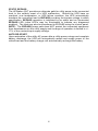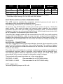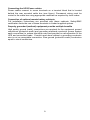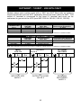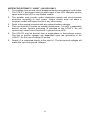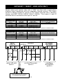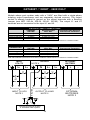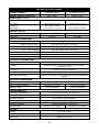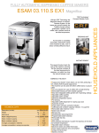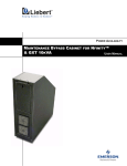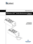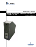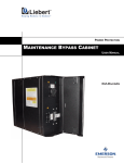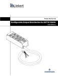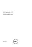
1
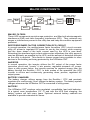
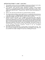
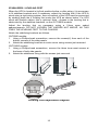
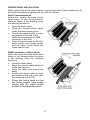
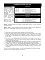
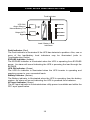
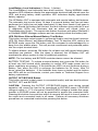
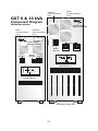
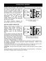
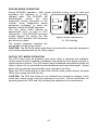
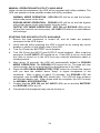
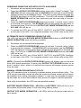
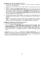
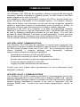
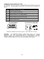
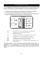
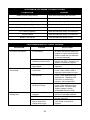
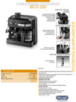
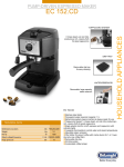
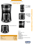
UPStation GXT™
6 & 10 kVA
208V & 240V
USER MANUAL
English
IMPORTANT SAFETY INSTRUCTIONS
WARNING: Opening or removing the cover may expose you to lethal voltages
within this unit even when it is apparently not operating and the input wiring is
disconnected from the electrical source. Observe all cautions and warnings in
this manual. Failure to do so MAY result in serious injury or death. Refer all
UPS and battery service to qualified service personnel. Do not attempt to
service this product yourself. Never work alone.
1. SAVE THESE INSTRUCTIONS. THIS MANUAL CONTAINS IMPORTANT
SAFETY INSTRUCTIONS. Read all safety, installation, and operating
instructions before installing and operating the Uninterruptible Power System
(UPS). Adhere to all warnings on the unit and in this manual. Follow all
operating and user instructions. Individuals without previous training can
operate this equipment.
2. This product is designed for Commercial/Industrial use only. It is not intended
for use with life support and other designated “critical” devices. Maximum
load must not exceed that shown on the UPS rating label. The UPS is
designed for data processing equipment. If uncertain, consult your dealer.
See Limited Warranty.
3. This UPS is designed for use on a properly grounded (earthed), 208-240
VAC, 50Hz or 60Hz supply, for installation by qualified personnel. A qualified
electrician must review and approve customer supplied wiring, circuit
breakers, intended loads, and verify correct input, output and ground
connections to ensure compliance with technical standards and local
electrical codes of practice. Installation instructions and warning notices only
for use by qualified personnel are located after the UPS operator instructions
in this manual.
4. ELECTROMAGNETIC COMPATIBILITY - The GXT 6 & 10 kVA complies with
the limits for a Class A digital device, pursuant to Part 15 of FCC rules.
These limits provide reasonable protection against harmful interference in a
commercial environment. This device generates, uses, and radiates radio
frequency energy and, if not installed and used in accordance with the
instruction manual, may cause harmful interference to radio communications.
Operating this device in a residential area is likely to cause harmful
interference, which the user must correct at his own expense.
5. Operate the UPS in an indoor environment only in an ambient temperature
range of 0°C to +40°C (32°F to +104°F). Install it in a clean environment, free
from moisture, flammable liquids, gasses, or corrosive substances.
6. This UPS contains no user serviceable parts. The UPS ON/OFF pushbuttons
do not electrically isolate internal parts. Under no circumstances attempt to
gain access internally, due to the risk of electric shock or burn.
Do not continue to use the UPS if the front panel indications are not in
accordance with these operating instructions, or the UPS performance alters
in use. Refer all faults to your dealer.
7. Only trained engineers authorized by Liebert should perform troubleshooting.
To replace batteries, refer all servicing to qualified service personnel.
PROPER DISPOSAL OF BATTERIES IS REQUIRED. REFER TO YOUR
LOCAL LAWS AND REGULATIONS FOR DISPOSAL REQUIREMENTS.
2
8. Never block or insert any object into the ventilation holes or other openings.
9. DO NOT CONNECT equipment that could overload the UPS or demand DC
current from the UPS, for example: electric drills, vacuum cleaners, laser
printers, hairdryers or any appliance using half wave rectification.
10. Storing magnetic media on top of the UPS may result in data loss or
corruption.
11. Turn the UPS off and isolate the UPS before cleaning. Use only a soft cloth,
never liquid or aerosol cleaners. Keep the front and rear vents free of dust
accumulation that could restrict airflow.
GLOSSARY OF SYMBOLS
Indicates AC Input
Indicates AC Output
Indicates Caution: Note the accompanying instruction
Indicates the position of a fuse
Requests the user to consult the manual for additional
information
Indicates that the unit contains a valve regulated lead acid battery
3
INTRODUCTION
Congratulations on your choice of the UPStation GXT™ Uninterruptible Power
System (UPS). It provides conditioned power to microcomputers and other
sensitive electronic equipment.
Upon generation, AC power is clean and stable. However, during transmission
and distribution it may be subject to voltage sags, spikes, or complete power
failure, which may interrupt computer operations, cause data loss, or even
damage equipment. The UPStation GXT protects equipment from these
disturbances.
The UPStation GXT is an “on-line” UPS that continuously conditions and
regulates its output voltage, whether the utility power is present or not. It
supplies connected equipment with clean sinewave power. Sensitive electronic
equipment operates best from sinewave power. The GXT 6000/10000T-208X,
and 240X models have an additional output isolation transformer.
For ease of use, the UPStation GXT contains a light emitting diode (LED) display
to indicate either “load percentage” or “battery capacity” depending upon the
mode of operation. It also provides self-diagnostics, a combination On/Alarm
Silence/Manual Battery Test button, a combination Off/Bypass button, and two
levels of alarms when the unit is operating on battery.
The UPStation GXT has an interface port for communications between the UPS
and a LAN server or other computer system. This port provides detailed
operating information including voltages, currents, and alarm status to the host
system when used in conjunction with the SiteNet® 2 software. SiteNet® 2
software can also remotely control UPS operation.
4
MAJOR COMPONENTS
Rectifier/PFC
INPUT
Output Transformer
GXT 208X, 230X, &
240X models only
Inverter
EMI/RFI
Filter
EMI/RFI
Filter
OUTPUT
Static Bypass
Battery
Battery
Charger
EMI /RFI FILTERS
These UPS components provide surge protection, and filter both electromagnetic
interference (EMI) and radio frequency interference (RFI). They minimize any
surges or interference present in the utility line and keep the sensitive equipment
protected.
RECTIFIER/POWER FACTOR CORRECTION (PFC) CIRCUIT
In normal operation, the rectifier/power factor correction (PFC) circuit converts
utility AC power to regulated DC power for use by the inverter, while ensuring
that the wave shape of the input current used by the UPS is near ideal.
Extracting this sinewave input current achieves two objectives: the utility power is
used as efficiently as possible by the UPS, and the amount of distortion reflected
on the utility is reduced. This results in cleaner power being available to other
devices in the building not being protected by the UPStation GXT.
INVERTER
In normal operation, the inverter utilizes the DC output of the power factor
correction circuit and “inverts” it into precise, regulated sinewave AC power.
Upon a utility power failure, the inverter receives its required energy from the
battery through the Rectifier / PFC. In both modes of the operation, the UPS
inverter is on-line and continuously generating clean, precise, regulated AC
output power.
BATTERY CHARGER
The battery charger utilizes energy from the Rectifier / PFC and precisely
regulates it to continuously “float” charge the battery system. The battery system
charges whenever the UPStation GXT is connected to utility power.
BATTERY
The UPStation GXT employs valve regulated, nonspillable, lead acid batteries.
At a typical room temperature (70° F) and with the UPS float charging, the
battery system will last many years. Optional external battery cabinets are
available to provide extended run times.
5
STATIC BYPASS
The UPStation GXT provides an alternate path for utility power to the connected
load, in the unlikely event of a UPS malfunction. Should the UPS have an
overload, over temperature, or UPS failure condition, the UPS automatically
transfers the connected load to BYPASS providing the bypass voltage is within
specification. BYPASS operation is indicated by an alarm and an illuminated
BYPASS LED (other LED’s may be illuminated to indicate any diagnosed
problem). The load may also be transferred to BYPASS using the control panel.
NOTE: The BYPASS power path does NOT protect the connected equipment
from disturbances on the utility supply and its range of operation is limited to +/17% of the nominal input supply voltage.
AUTO RE-START
Upon restoration of the utility AC power after a utility power outage and complete
battery discharge, the UPS will automatically restart and supply power to the
critical load and the battery charger will automatically recharge the battery.
6
INSTALLATION
These instructions are for use by competent personnel only.
INSTALLATION CONSIDERATIONS
Detailed instructions to help you install the UPS are provided in the following
pages; however, you should give some consideration to the proposed
environment in which the UPS is to be installed, and carry out some preparatory
work.
UNPACKING AND INSPECTION
Follow unloading instructions printed on the carton. Do not discard any
packaging until installation is complete, check that you have removed to a safe
place the user manual, stabilizing brackets, and any other items shipped with the
unit to be used in its installation.
CAUTION: GXT6000 UPS weighs up to 173kg (381lbs) and the GXT10000 UPS
weighs up to 287kg (633lbs). Use adequate handling aids when moving or
installing the UPS. The UPS is fitted with castor wheels for easy movement. Take
care when the UPS is removed from its packing and being wheeled across an
uneven floor without the stabilizers fitted, that it does not tip over.
Before you install the UPS, give it a thorough visual examination to ensure it has
not been subjected to shipping damage. If it is not in perfect condition, you
should advise both the shipper and the supplier immediately. DO NOT ATTEMPT
TO INSTALL A DAMAGED UPS.
IMPORTANT - Check the UPS rating plate that the UPS is suitable for operation
on your UTILITY voltage and load voltage requirements before installing.
LOCATION
Locate the UPStation GXT indoors in a controlled environment, where it cannot
be accidentally disconnected. Locate it in an area with unrestricted airflow, away
from water, flammable liquids, gases, corrosives, or conductive contaminants.
Air vents are located at the front and the rear of the UPS. Do not position the
UPS in an enclosed space where airflow is restricted. Allow at least 150mm (6
inches) free space around the UPS, with a minimum of 300mm (12 inches) at the
back to enable easy operator access to the rear panel mounted
input/output/battery circuit breakers.
Electrical maintenance/servicing requires access to all four sides of the UPS,
provide the necessary free space or use a flexible wiring system to allow the
UPS to be pulled forward.
Maintain an ambient temperature range of 0 - +40° centigrade (32-104° F)
NOTE- UPS operation in temperatures above 25°C (77°F) reduces battery life.
7
Model
#
GXT6000T
GXT10000T
AIRFLOW
Cfm
130
270
m 3h
221
459
DISSIPATION*
Watts
504
840
K Btu/hr
1.7
2.8
OUTPUT
RATING**
VA
6000
10000
Watts
4200
7000
* Increase dissipation 25% for 208X, and 240X transformer models.
** Decrease output rating 10% for 208 and 208X model.
ELECTRICAL INSTALLATION CONSIDERATIONS
This UPS must be installed by competent electrical personnel and wired in
accordance with local/national electrical codes.
The following information is provided for your guidance.
On start-up, the UPS will take a half cycle inrush current of up to 3 times the
rated current. This must be taken into account when selecting the overload
protection device at the input Utility supply distribution point. To avoid random
tripping on start-up, we recommend that the input Utility supply be protected with
an MCB capable of withstanding this initial inrush.
The utility input supply cable must be connected to the UPS via a wall mounted
double pole circuit breaker, rated to carry the input current and be capable of
breaking the maximum prospective short circuit current of this branch circuit. The
breaker is to be mounted within six feet of the UPS and be readily accessible to
the operator.
ELECTRICAL CONNECTIONS
The UPS is supplied with an input/output/battery terminal block assembly on the
rear of the UPS within a cable box. (see outline drawing) The cable box (gland
plate) can be removed to enable knockouts to be removed, or new holes drilled,
to secure the cables.
The cable sizes and distribution methods used during installation are subject to
local/national electrical codes of practice, and therefore are not detailed here.
The following tables detail the standard current ratings. The UPS rating plate
gives details of the current ratings for alternative output voltages.
The terminals will accept wire sizes up to the values below:
GXT6000 = 8 AWG
GXT10000 = 6 AWG
Recommended for all GXT6000 wiring.
Recommended for all GXT10000 wiring.
(75°C copper wire)
Terminal tightening torque is 35 in-lb.
8
Connecting the UPS Power cables
Power cables connect to screw terminals on a terminal block that is located
behind the rear mounted cable box (see figure). Permanent wiring must be
routed to the cable box using appropriate materials as required by local codes.
Connection of optional remote battery cabinets
Full installation instructions are provided with these cabinets. Safety/EMC
certification limits the use of these terminals to Liebert supplied options.
Properly grounded (earthed) equipment provide multiple benefits
High quality ground (earth) connections are required for the equipment ground
conductors (protective earth) and grounding electrode conductor (power system
earth connection) to reduce electrical noise and provide for safe operation of the
UPS and connected loads. Conduit used alone without a grounding conductor
wire is not an acceptable connection. Size ground (protective earth) conductors
equal to circuit conductors.
9
GXT6000T / 10000T - 208 UPS ONLY
Models whose part number ends with a “208” are NOT fitted with an isolating
output transformer and are NOT separately derived sources under the NEC. The
output L1 terminal is connected to the input L1 terminal and must not be
connected to ground at the UPS (see NEC 250-5d, 250-26, 250.91, 250.92).
GXT6000T-208 CONNECTIONS
CONNECTION
CURRENT
RATING
Recommended
Wire Size
Recommended External
Overcurrent Protection
INPUT
OUTPUT
BATTERY
28 AMPS
26 AMPS
23 AMPS
8 AWG (10 mm²)
8 AWG (10 mm²)
8 AWG (10 mm²)
40 AMPS
SIZE GROUNDING (PROTECTIVE EARTH) CONDUCTORS EQUAL TO CIRCUIT CONDUCTORS
GXT10000T-208 CONNECTIONS
CONNECTION
CURRENT
RATING
Recommended
Wire Size
Recommended External
Overcurrent Protection
INPUT
OUTPUT
BATTERY
45 AMPS
43 AMPS
37 AMPS
6AWG (16 mm²)
6AWG (16 mm²)
6AWG (16 mm²)
60 AMPS
SIZE GROUNDING (PROTECTIVE EARTH) CONDUCTORS EQUAL TO CIRCUIT CONDUCTORS
INPUT
UTILITY
L1
OUTPUT
NOTE 4
L2
L1
L2
+
208
208
NOTE 6
NOTE 5
INPUT TO UPS
NOTE 1
OPTIONAL
BATTERY
OUTPUT TO LOAD
NOTE 2
10
OPTIONAL
BATTERIES
NOTE 3
-
NOTES FOR GXT6000T / 10000T - 208 UPS ONLY
1. The installer must provide circuit breaker protection according to local codes.
The UTILITY disconnect must be within sight of the UPS. Maintain service
space around the UPS or use flexible conduit.
2. The installer must provide output distribution panels and circuit breaker
protection according to local codes. Output circuits must not share a
common conduit with input circuits or any other wiring.
3. Refer to the manual provided with any optional battery cabinets.
4. This unit does NOT contain an isolating transformer. It is NOT a separately
derived source. System grounding is provided at the UTILITY. Do not
connect any output circuit conductor to ground at the UPS.
5. The UTILITY may be derived from a single-phase or three-phase source.
The line to ground voltages are dependant upon the grounding of the
UTILITY. Do not use a floating AC source.
6. Output L1 is connected directly to the Input L1. The line-ground voltages will
match the input line-ground voltages.
11
GXT6000T / 10000T - 208X UPS ONLY
Models whose part number ends with a “208X” are fitted with a single-phase
isolating output transformer and are separately derived sources. The output
neutral is already bonded to ground on the output terminals with a Bonding
Jumper (see NEC 250-5d, 250-26, 250.91, 250.92). The output L1 and L2
terminals are not connected to the input L1 and L2.
GXT6000T-208X CONNECTIONS
CONNECTION
CURRENT
RATING
Recommended
Wire Size
Recommended External
Overcurrent Protection
INPUT
OUTPUT @ 208V
OUTPUT @ 120V
BATTERY
28 AMPS
26 AMPS
45 AMPS
33 AMPS
8 AWG (10 mm²)
8 AWG (10 mm²)
8 AWG (10 mm²)
8 AWG (10 mm²)
40 AMPS
SIZE GROUNDING (PROTECTIVE EARTH) CONDUCTORS EQUAL TO CIRCUIT CONDUCTORS
GXT10000T-208X CONNECTIONS
CONNECTION
CURRENT
RATING
Recommended
Wire Size
Recommended External
Overcurrent Protection
INPUT
OUTPUT @ 208V
OUTPUT @ 120V
BATTERY
45 AMPS
43 AMPS
75 AMPS
39 AMPS
6AWG (16 mm²)
6AWG (16 mm²)
6AWG (16 mm²)
6AWG (16 mm²)
60 AMPS
SIZE GROUNDING (PROTECTIVE EARTH) CONDUCTORS EQUAL TO CIRCUIT CONDUCTORS
INPUT
UTILITY
L1
OUTPUT
OPTIONAL
BATTERY
NOTE 4
L2
N
L1
L2
L2A
+
208
120
208
120
0
NOTE 6
240
NOTE 5
INPUT TO UPS
NOTE 1
OUTPUT TO LOAD
NOTE 2
Grounding Electrode System
or Protective Earth System
12
OPTIONAL
BATTERIES
NOTE 3
-
NOTES FOR GXT6000T / 10000T - 208X UPS ONLY
1. The installer must provide circuit breaker protection according to local codes.
The utility disconnect must be within sight of the UPS. Maintain service
space around the UPS or use flexible conduit.
2. The installer must provide output distribution panels, circuit breaker
protection, or emergency disconnect switches according to local codes.
Output circuits must not share a common conduit with input circuits or any
other wiring. IMPORTANT - Distribute any 120VAC loads evenly between L1
AND L2A. Do not connect loads between the output terminals L2-N or L2L2A. These are not standard voltages.
3. Refer to the manual provided with any optional battery cabinets.
4. The single-phase isolating output transformer is a separately derived source.
The output neutral is already bonded to ground on the output terminals with
a Bonding Jumper. No other bonding wire is needed. (see NEC 250-5d,
250-26, 250.91, 250.92)
5. Install an 8 AWG (10 mm2) (75° C copper wire) (minimum size, see NEC
250-5d, 250-81, 250-83, table 250-94) grounding electrode conductor
between the grounded circuit conductor (neutral) and the nearest effectively
grounded metal structural member, nearest effectively grounded metal water
pipe, or other grounding electrode in the grounding electrode system. If the
grounding electrode conductor must be protected, non-metal conduit is
recommended. If metal conduit must be used, bond both ends of the conduit
to the grounding electrode conductor. Conduit is not an acceptable
grounding electrode conductor.
6. The utility may be derived from a single-phase or three-phase source. The
line to ground voltages are dependant upon the grounding of the utility and
do not affect the output voltages. Do not use a floating AC source.
13
GXT6000T / 10000T - 240X ONLY
Models whose part number ends with a “240X” are fitted with a single-phase
isolating output transformer and are separately derived sources. The output
neutral is already bonded to ground on the output terminals with a Bonding
Jumper (see NEC 250-5d, 250-26, 250.91, 250.92). The output L1 and L2
terminals are not connected to the input L1 and L2.
GXT6000T-240X CONNECTIONS
CONNECTION
CURRENT
RATING
Recommended
Wire Size
Recommended External
Overcurrent Protection
INPUT
OUTPUT @ 230V
OUTPUT @ 120V
BATTERY
27 AMPS
25 AMPS
50 AMPS
27 AMPS
8 AWG (10 mm²)
8 AWG (10 mm²)
8 AWG (10 mm²)
8 AWG (10 mm²)
40 AMPS
SIZE GROUNDING (PROTECTIVE EARTH) CONDUCTORS EQUAL TO CIRCUIT CONDUCTORS
GXT10000T-240X CONNECTIONS
CONNECTION
CURRENT
RATING
Recommended
Wire Size
Recommended External
Overcurrent Protection
INPUT
OUTPUT @ 230V
OUTPUT @ 120V
BATTERY
44 AMPS
42 AMPS
83 AMPS
44 AMPS
6AWG (16 mm²)
6AWG (16 mm²)
6AWG (16 mm²)
6AWG (16 mm²)
60 AMPS
SIZE GROUNDING (PROTECTIVE EARTH) CONDUCTORS EQUAL TO CIRCUIT CONDUCTORS
INPUT
UTILITY
L1
OUTPUT
OPTIONAL
BATTERY
NOTE 4
L2
N
L2
+
-
240
120
240
120
0
NOTE 6
NOTE 5
INPUT TO UPS
NOTE 1
L1
OUTPUT TO LOAD
NOTE 2
Grounding Electrode System
or Protective Earth System
14
OPTIONAL
BATTERIES
NOTE 3
NOTES FOR GXT6000T / 10000T - 240X ONLY
1. The installer must provide circuit breaker protection according to local codes.
Maintain service space around the UPS or use flexible conduit.
2. The installer must provide output distribution panels, circuit breaker
protection, or emergency disconnect switches according to local codes.
Output circuits must not share a common conduit with input circuits or any
other wiring. IMPORTANT - Distribute any 120VAC loads evenly between L1
AND L2.
3. Refer to the manual provided with any optional battery cabinets.
4. The single-phase isolating output transformer is a separately derived source.
The output neutral is already bonded to ground on the output terminals with
a Bonding Jumper. (see NEC 250-5d, 250-26, 250.91, 250.92)
5. Install an 8 AWG (10 mm2) (75° C copper wire) (minimum size, see NEC
250-5d, 250-81, 250-83, table 250-94) grounding electrode conductor
between the grounded circuit conductor (neutral) and the nearest effectively
grounded metal structural member, nearest effectively grounded metal water
pipe, or other grounding electrode in the grounding electrode system. If the
grounding electrode conductor must be protected, non-metal conduit is
recommended. If metal conduit must be used, bond both ends of the conduit
to the grounding electrode conductor. Conduit is not an acceptable
grounding electrode conductor.
6. The utility may be derived from a single-phase or three-phase source. The
line to ground voltages are dependant upon the grounding of the utility and
do not affect the output voltages. Do not use a floating AC source.
15
STABILIZERS / LEVELING FEET
When the UPS is located in its final position before or after wiring, it is necessary
to fit stabilizer brackets and, if necessary, adjust the leveling feet. If the UPS is
wired using a rigid wiring system, then movement of the UPS must be prevented
by winding down the 4 leveling feet under the UPS as shown below. For UPS
wired with flexible cables, this is optional. Note - Access to the leveling feet is
obstructed by the stabilizer brackets, on the GXT10000 models.
Adjust the leveling feet as necessary using a 12mm open ended
spanner/wrench. DO NOT LOOSEN THE LARGER NUT ABOVE, AS THIS
FIXES THE LEVELING FEET TO THE CHASSIS
Attach the stabilizing brackets as follows.
GXT6000 models:
1. Using a Phillips-head screwdriver, remove the screws(4) from each of the
bottom corners of the side panels.
2. Attach the stabilizing brackets to each corner using screws just removed.
GXT10000 models :
1. Using a Phillips-head screwdriver, remove the three inner-most screws at
the base of both side panels.
2. Attach the stabilizers fixing with the screws just removed.
6 kVA
10 kVA
12 mm
Leveling Feet Adjustment Diagram
16
FERRITE BEAD INSTALLATION
When using either of the options below, to reduce the risk of radio interference, fit
the ferrite assemblies supplied with the UPS as follows:
Serial Communications
Attach the smaller enclosed ferrite
bead clamp to the communication
cable as shown in the drawing using
the following directions:
•
•
•
•
Open the ferrite bead.
Place the communication cable
inside the ferrite bead groove.
Position the ferrite beads as close
as possible to the end of the
cable that connects to the DB9
connector of the UPS.
Close the ferrite bead so that the
ferrite bead’s case snaps closed
with the cable routed inside the
ferrite bead’s case.
SNMP Installation ( When fitted)
Attach the larger enclosed ferrite bead
clamp to the network cable as shown
in the drawing using the following
directions:
•
•
•
•
•
Open the ferrite bead.
Place the network cable inside the
ferrite bead groove.
Wrap the cable once around the
bead.
Position the ferrite cable as close
as possible to the end of the cable
that connects to the UPS.
Close the ferrite bead so that
the ferrite bead’s case snaps
closed with the cable routed
inside the ferrite bead’s case.
17
COMMISSIONING THE UPS
Output Voltage
Selector Switches
The Output Voltage
Selector Switches,
located on the rear
of the UPS, are
designed to allow
selecting
or
changing the desired
output voltage to
match the utility.
The
settings
to
choose from are
208, 220, 230 and
240 VAC output.
240X Units
208 / 104
áá - both switches up
220 / 110
áâ - first switch up, second down
230 / 115
ââ - both switches down
240 / 120
âá - first switch down, second up
(Factory Default)
208X Units
Output voltage will be 208/120 regardless of switch position.
208 Units
208 V
áá - both switches up (Factory Default)
220 V
áâ - first switch up, second down
230 V
ââ - both switches down
240 V
âá - first switch down, second up
NOTE: NEVER change the switch settings while UPS is on and powering
connected loads.
NOTE: Setting output voltage to 208 VAC will cause UPS unit to be derated to
90% of the VA and Watt rating listed in specification section.
1. Adjust the output voltage switch settings to the desired value.
2. Follow the instructions for Powering up the UPS referenced earlier in this
manual. Sequence through the operating modes, using the front panel
pushbuttons, in accordance with operating instructions to check functionality
of the UPS.
3. Set the UPS to NORMAL MODE OPERATION- UPS mode. Check on the
output terminals of the UPS, for the correct output voltage for the voltage
rating of the intended loads.
4. In NORMAL MODE OPERATION- UPS mode, power up customers load and
check that it is within the UPS rating by observing the front panel LED’s
5. In UPS mode, press the UPS ON/ALARM /BATTERY TEST pushbutton to
carry out battery test and ensure the load can be supported. Note - Full
battery capacity will not be available until a battery recharge cycle has been
completed.
The UPS is now ready for service. In case of problems refer to the fault finding
section or call your local distributor for advice.
18
CONTROLS AND INDICATORS
Fault Indicator
UPS ON /
Alarm Silence /
Manual Battery Test
BYPASS
UPS ON
BATTERY
Output OFF /
Bypass
AC INPUT
Load / Battery Level
Indicators
Fault Indicator (Red)
The Fault indicator is illuminated if the UPS has detected a problem. Also, one or
more of the load/battery level indicators may be illuminated (refer to
Troubleshooting Guide).
BYPASS Indicator (Amber)
The BYPASS indicator is illuminated when the UPS is operating from BYPASS
power. An alarm will sound indicating the UPS is powering the load through the
BYPASS.
UPS ON Indicator (Green)
The UPS On indicator is illuminated when the UPS inverter is operating and
supplying power to your connected loads.
Battery Indicator (Amber)
The Battery indicator is illuminated when the UPS is operating from the battery
system. An alarm will sound indicating the UPS is powered from batteries.
AC Input Indicator (Green)
The AC Input indicator is illuminated when utility power is available and within the
PFC input specification.
19
Load/Battery Level Indicators (4 Green, 1 Amber)
The Load/Battery Level indicators have dual functions. During NORMAL mode
operation LED indicators display the approximate electrical load placed upon the
UPS; and during battery mode operation LED indicators display approximate
battery capacity.
The UPStation GXT is equipped with automatic and remote battery test features.
The automatic test occurs every 14 days if a manual battery test has not been
performed or if utility has not been interrupted (14 day timer resets if unit goes to
battery). Should the battery fail this test, the fault indicator along with the A and
C diagnostic LEDs will illuminate and an alarm will sound (refer to
Troubleshooting Guide). The remote test feature functions with either SiteNet® 2
or SiteNet® SNMP Manager software and can remotely initiate the battery test.
UPS ON/Alarm Silence/Manual Battery Test Button
This button controls output power to connected load(s) and has three functions:
UPS ON, Alarm Silence, and Manual Battery Test. To start the UPS, while in the
BYPASS mode, press the ON button until the command is acknowledged by a
beep from the audible alarm. This will provide conditioned and protected power
into the output terminal block.
To silence alarms; press the ON button for at least one half second while alarm
conditions are present. After the alarm is silenced, the UPStation GXT will
reactivate the alarm system to alert of additional problems.
NOTE: The low battery and BYPASS reminder alarms cannot be silenced.
BATTERY TESTING - To initiate a manual battery test, press the ON button for
at least one half second while operating in normal UPS mode power and no
alarm conditions are present. If the bottom two LED's do not illuminate during a
Battery Test, allow the UPS to recharge the batteries for 24 hours. After 24
hours, retest the batteries. If the batteries have been re-tested and the bottom
two LED's still do not illuminate, contact your dealer or Technical Support for a
battery replacement.
OUTPUT OFF/BYPASS Button
This button controls output power to connected load(s) and has dual functions:
OUTPUT OFF and BYPASS.
CAUTION: Pressing the OUTPUT OFF/BYPASS button once during normal
operation will cause the load to be transferred to BYPASS power if BYPASS
voltage is within +/- 17% of nominal. If the BYPASS voltage is outside this range,
transfer to BYPASS power will not be permitted to protect the connected load.
Pressing this button a second time within 4 seconds will result in loss of power to
the output and connected loads in all cases. Perform all necessary shutdown
procedures on connected loads before pressing this button.
20
TM
Intellislot
Communications
Port
DB-9
Communications
Port
GXT 6 & 10 kVA
Component Diagram
208 Models Shown
DB-9
Communicaions
Port
Output Voltage
Selector Switches
TM
Intellislot
Communications
Port
Output Voltage
Selector Switches
Breakers
Battery
Breaker
Input
Breaker
Battery
Breaker
Input
Output
Output
Breaker
Hardwire
Terminal Blocks
Hardwire
Terminal Blocks
Adjustable leveling feet
21
OPERATING MODES
NORMAL MODE OPERATION- UPS mode
During normal operation, utility power provides energy to the UPS. The filters,
the power factor correction circuit and
the inverter process this power to
provide computer grade power to
connected loads. The UPS maintains
the batteries in a fully charged state.
The four green Leads indicate an
approximate level of load in 25%
increments.
If the UPS becomes
loaded beyond full rating, the fifth
(amber) LED indicator will illuminate
and sound an alarm.
The display template indicates the
percentage of load on the UPS output.
Normal Mode Operation at
51-75% loading
BATTERY MODE OPERATION
Battery mode occurs in event of an
extreme input voltage condition or
complete utility failure. The battery
system supplies power through the
Rectifier / PFC to the inverter to
generate power for the connected
load.
During battery mode the AC Input LED
will extinguish, and the Battery LED will
illuminate to warn that a utility problem
has occurred. An alarm will sound
Battery Mode Operation at
every 10 seconds. This will change to
81-100% battery capacity
2 beeps every 5 seconds when battery
runs low (approximately 2 minutes
remaining). . Each load/battery level indicator represents a 20% capacity level.
As capacity decreases, fewer indicators remain illuminated. Refer to the
Troubleshooting Guide.
To increase this time, turn off non-essential pieces of equipment (such as idle
computers and monitors) or add optional external battery cabinets.
CAUTION: Turning off the UPS while in battery mode will result in loss of output
power.
Once utility power is restored, the UPS resumes normal operation. At this time,
the Battery Charger begins recharging the battery.
22
BYPASS MODE OPERATION
During BYPASS operation, utility power provides energy to your load and
maintains the batteries in a fully
charged state. The BYPASS will
automatically
power
the
load
temporarily during overloads of the
inverter, when diagnostics detect
equipment problems, or when the
operator selects BYPASS operation.
The four green LEDs indicate an
approximate level of load in 25%
increments. If the BYPASS becomes
loaded beyond full rating, the fifth
Bypass Mode Operation at
(amber) LED indicator will illuminate
51-75% loading
and sound an alarm.
The display template indicates the
percentage of load on the output.
CAUTION: The BYPASS power path does not protect the connected equipment
from severe disturbances on the utility supply.
OUTPUT OFF MODE OPERATION
The UPS output may be disabled even when utility or batteries are available.
Output power may be enabled or disabled using both the front panel controls or
communication options. The UPS output may be disabled automatically when the
utility is absent for an extended time and batteries have been discharged. Output
power will be restored automatically upon restoration of utility.
When the UPS is standing by in this mode with the utility power absent, all panel
LEDs and cooling fans will turn off.
CAUTION: The UPS and loads are not isolated from hazardous voltages in this
mode and output power could be restored at any time. Follow instructions for
powering down the UPS and fully isolating the equipment for maintenance.
23
MANUAL OPERATION WITH UTILITY AVAILABLE
Under normal circumstances, the UPS will be operated with utility available. The
UPS can operate in three possible modes with utility available:
NORMAL MODE OPERATION - UPS ON LED will be on and the inverter
will provide power to the load.
BYPASS MODE OPERATION - BYPASS LED will be on and the bypass
will provide power to the load directly from the utility.
OUTPUT OFF MODE OPERATION - UPS ON and BYPASS LEDs will be
off and the load will not have power. AC LINE LED will be on and batteries
will recharge.
STARTING THE UPS WITH UTILITY AVAILABLE
1. Ensure the load equipment is turned off, and all loads are properly
connected to the UPS output.
2. Verify that the utility supplying the UPS is turned on by closing any circuit
breaker or switch on the supply side of the UPS.
3. Turn On (Close) the BATTERY circuit breaker.
4. Turn ON (Close) the INPUT and OUTPUT circuit breakers. After a start-up
sequence, the AC INPUT LED should be on. If this LED is not on, verify that
the utility is turned on to the UPS from any external distribution panel or
isolating switch.
5. After about 10 seconds, the UPS will automatically default to BYPASS
MODE OPERATION. The BYPASS LED should be on. The load will now
receive power, but is not protected from disturbances in the utility.
6. Press the UPS ON/ALARM/BATTERY TEST button for at least one second
until you hear the audible alarm "beep" to signal acceptance of the
command. After a delay of about 10 seconds, the BYPASS LED will
extinguish, and the UPS ON LED should light. The UPS will then initiate a
self-test and battery test. When these tests are complete, the UPS is ready
for NORMAL UPS OPERATION.
7. Confirm that the UPS ON and AC INPUT LEDs are on and the BATTERY
and BYPASS LEDs are off.
8. Connected load equipment may now be turned on.
24
POWERING DOWN THE UPS WITH UTILITY AVAILABLE
1. Shutdown all connected load equipment.
2. Press the OUTPUT OFF/BYPASS button once until a "beep" is heard. The
UPS ON LED will extinguish and the BYPASS LED will light if the BYPASS
voltage is within an acceptable range. The load is now powered through the
BYPASS and there is no UPS protection. The UPS will remain in BYPASS
MODE OPERATION until the user continues with the next step to turn the
UPS off.
3. Press the OUTPUT OFF/BYPASS button for at least 1 second, twice, within
a 4 second time interval. The BYPASS LED will extinguish and all power to
the load will stop. The UPS is in OUTPUT OFF MODE OPERATION and the
AC LINE LED will be on.
4. To isolate the UPS, turn off the INPUT, OUTPUT, and BATTERY breakers
on the rear of the UPS. For complete isolation, turn off the utility to the UPS.
ALTERNATE QUICK POWERING DOWN THE UPS
The UPS will skip past BYPASS MODE OPERATION directly to OUTPUT OFF
MODE OPERATION even with utility available.
1.
2.
3.
Shutdown all connected load equipment.
Press the OUTPUT OFF/BYPASS button for at least 1 second, twice, within
a 4 second time internal. The UPS ON LED will extinguish and the BYPASS
LED will light for a short period then extinguish and all power to the load will
stop. The UPS is in OUTPUT OFF MODE OPERATION and the AC LINE
LED will be on.
To isolate the UPS, turn off the INPUT, OUTPUT, and BATTERY breakers
on the rear of the UPS. For complete isolation, turn off the utility to the UPS.
NOTE: Pressing the OUTPUT OFF/BYPASS button will always remove the load
from UPS power protection. Pressing the OUTPUT OFF/ BYPASS button for at
least 1 second, twice, within a 4 second time interval will always remove power
from the load.
MANUAL OPERATION WITHOUT UTILITY
The UPS operating time is limited by available battery power without utility. The
UPS may be manually turned off after the loads have been turned off to prevent
the batteries from being completely drained. It may also be desirable to power
up the loads for a short time without utility power to support a critical operation.
With utility unavailable, the UPS has two possible modes:
BATTERY MODE OPERATION - UPS ON and BATTERY LEDs will be on and
the inverter will provide power to the load using battery power.
OUTPUT OFF MODE OPERATION – All LED’s will be off and the load will not
have power.
25
POWERING UP THE UPS WITHOUT UTILITY
1. Ensure the load equipment is turned off, and all loads are properly
connected to the UPS output.
2. Verify that the BATTERY, INPUT, AND OUTPUT circuit breakers remain
closed.
3. Press the UPS ON/ALARM/BATTERY TEST button for at least one second
until you hear the audible alarm emit a “double beep" to signal acceptance of
the command. After a short delay, the BATTERY LED should light. The
UPS will then initiate a self-test and approximately 10 seconds after these
tests are completed, the UPS ON and BATTERY LEDs will light indicating
that the batteries now power the load.
4. Connected loads may now be started. If the utility is not restored before the
batteries are fully discharged, the UPS will automatically turn off all power to
the load.
NOTE: Closely monitor remaining stored energy using the battery capacity
LEDs or communication option. If an orderly shutdown of the load is
required, it must be completed before the batteries are fully discharged.
POWERING DOWN THE UPS WITHOUT UTILITY
1. Shutdown all connected load equipment.
2. Press the OUTPUT OFF/BYPASS button once until a "beep" is heard. The
UPS will switch from BATTERY MODE OPERATION to OUTPUT OFF
MODE OPERATION. All LEDs will turn off and all power to the load will stop.
3. To isolate the UPS, turn off the INPUT, OUTPUT, and BATTERY breakers on
the rear of the UPS. For complete isolation, turn off the AC supply to the
UPS.
CAUTION: When the UPS is in OUTPUT OFF MODE OPERATION without
UTILITY, control panel LEDs and cooling fans will be off. The UPS is not
disabled and output power could be restored at any time. Do not attempt to
service the load or UPS without isolating the UPS.
26
COMMUNICATIONS
UPS MONITORING
The UPStation GXT UPS has the capability of being monitored with stand alone
computers, network workstations, network servers, or UNIX hosts via the DB-9
socket located on the rear of the UPS.
This capability is used in applications requiring the UPS to provide status and
power monitoring information to the computer system. For example, during a
Utility power failure, the information can be used by the computer’s operating
system or application program to automatically save information in buffers, to
close files, and shut down operations prior to battery capacity depletion.
Monitoring of the UPS via a computer is as easy as downloading SiteNet®
MultiLink™ free from our web site (www.liebert.com). A MultiLink cable may also
be built by following instructions provided on our web page. You may also
purchase a Liebert SiteNet® 1 shutdown kit (sold separately). Consult your local
Liebert representative to determine the correct software kit for your application.
The kit includes shutdown software and a special purpose cable.
UPS INTELLIGENT COMMUNICATIONS
The UPStation GXT UPS has the capability to communicate intelligently with
stand alone computers, network workstations, network servers, or UNIX hosts via
the DB-9 socket located at the rear of the UPS. By purchasing the optional
Liebert SiteNet® 2 software package (sold separately), intelligent
communications allows the following capabilities:
Quantitative monitoring of Utility and UPS power
Quantitative monitoring of internal UPS parameters
Periodic tests of battery quality and replacement notification
Timed and delayed shutdown of the UPS
Logging of power disturbances and anomalies
Consult your local Liebert sales representative for more information about
SiteNet® 2 software.
UPS INTELLISLOT™ COMMUNICATIONS
The UPStation GXT UPS contains an Intellislot™ communications port for the
optional internal MultiPort 4 card, AS400 card, or Ethernet SNMP card. Optional
SiteNet® SNMP Manager software is available to allow communication through
several network management systems to be used in conjunction with the
Intellislot SNMP card. Contact your local Liebert representative, dealer, or
reseller.
27
COMMUNICATIONS INTERFACE PORT
The UPStation GXT UPS contains a standard DB-9 socket located on the rear of
the UPS unit. Several signals are provided on this port and are assigned as
follows:
PIN
ASSIGNMENT DESCRIPTION
1
Low Battery (open collector)
2
UPS TxD (typical RS-232 levels)
3
UPS RxD (typical RS-232 levels)
4
Remote Shutdown (5-12V); battery operation
5
Common
6
Remote Shutdown (short to pin 5); any mode
7
Low Battery (open emitter)
8
Utility Fail (open emitter)
9
Utility Fail (open collector)
PIN ASSIGNMENT
COLLECTOR TO EMITTER*
*Maximum voltage and current on pins 1,7,8,9 is 80V DC; 10.0 mA.
CAUTION:
TO MAINTAIN SAFETY (SELV-Safety Extra Low Voltage)
BARRIERS AND FOR ELECTROMAGNETIC COMPATIBILITY, SIGNAL
CABLES SHOULD BE SEGREGATED AND RUN SEPARATE FROM ALL
OTHER POWER CABLES, BY 1inch (25mm) WHERE APPLICABLE.
28
TROUBLESHOOTING
The information below indicates various symptoms a user may encounter in the
event the UPStation GXT develops a problem. Use this information to determine
whether external factors cause the problem and how to remedy the situation.
1. The fault indicator will illuminate indicating the UPS detected a problem.
2. An alarm will sound, alerting that the UPS requires attention.
3. One or more additional load/battery level LED indicators will be illuminated to
provide a diagnostic aid to the operator, as described below:
Fault
BYPASS
UPS
ON
BATTERY
AC
INPUT
All.
A.
On bypass due to output overload (beep every half second)
On bypass due to over temperature condition
(beep every 4 seconds)
B.
On bypass due to DC bus over voltage (beep every 4 seconds)
D.
On bypass due to PFC failure (beep every 4 seconds)
E.
On bypass due to inverter failure (beep every 4 seconds)
A&C.
UPS failed battery test (long beep every minute)
C&E.
UPS shutdown due to command from communication port
(SNMP); no beep
The fault indicators will be illuminated indefinitely while battery charger is
operational, or for a maximum of 5 minutes while battery charger is not
operational. If a problem persists consult your dealer, or contact Technical
Support. World Wide Technical Support numbers are located at the end of this
manual.
29
AUDIBLE ALARM CONDITIONS
CONDITION
ALARM
Battery mode (utility failure)
One short beep every ten seconds
Low battery
Two short beeps every five seconds
Output overload (bypass)
One short beep every half second
Over temperature (bypass)
One second beep every four seconds
DC Bus over voltage (bypass)
One second beep every four seconds
PFC failure (bypass)
One second beep every four seconds
Inverter failure
One second beep every four seconds
Battery Test failure
Two second beep every minute
TROUBLESHOOTING GUIDE
PROBLEM
UPS fails to start when
on button is pressed
CAUSE
UPS is short circuited
or overloaded
Internal fuse is blown,
indicating internal fault
Battery indicator is
illuminated
Breaker not closed or
has tripped.
UPS input not
connected
UPS input protection
has opened
Utility voltage out of
UPS input range.
UPS has reduced
battery time
Batteries not fully
charged
UPS is overloaded
Batteries may not be
able to hold a full
charge due to age
30
SOLUTION
Ensure UPS is off. Disconnect
all loads and ensure nothing is
lodged in output terminal block.
Ensure loads are not defective
or shorted internally.
Do not attempt to open or
service the UPS. Contact your
dealer or technical support.
Close breaker or remove
overload.
UPS is operating from battery
mode, make certain UPS is
securely connected to source.
UPS is operating from battery
mode. Save data and close
applications. Replace UPS
input fuse or reset input
breaker, then restart UPS.
UPS is operating from battery
mode. Save data and close
applications. Ensure Utility
supply voltage is within
acceptable limits for UPS.
Apply input voltage for at least
24 hrs to recharge batteries.
Check load level display and
reduce load level
Replace batteries. Contact
your dealer or technical
support.
TROUBLESHOOTING GUIDE
PROBLEM
CAUSE
Fault indicators and all
load level LED's are
illuminated
UPS overloaded or load
equipment is faulty
Fault indicators and
diagnostic LED A are
illuminated
UPS internal fan has a
problem or UPS
shutdown due to
temperature condition.
Load is on bypass
power.
Fault indicators and
diagnostic LED B are
illuminated
Fault indicators and
diagnostic LED D are
illuminated
Fault indicators and
diagnostic LED E are
illuminated
Fault indicators and
diagnostic LED A & C
are illuminated
Fault indicators and
diagnostic LED C & E
are illuminated
UPS internal DC bus
over voltage
UPS PFC fault.
UPS inverter fault.
UPS failed the battery
test.
UPS shutdown due to a
command from the
communications port(s)
31
SOLUTION
Check load level display and
remove non-essential loads.
Recalculate load VA and
reduce number of loads
connected to UPS. Check load
equipment for faults.
Press Alarm silence button.
Ensure that there are no
obstructions in front panel
vents or on rear panel fans;
and UPS is not overloaded.
Once the temperature is
reduced, the UPS will restart
and transfer the connected
equipment to inverter power
automatically.
UPS requires service. Contact
your dealer or technical
support.
UPS requires service. Contact
your dealer or technical
support.
UPS requires service. Contact
your dealer or technical
support.
Replace batteries. Contact
your dealer or technical
support.
Your UPS has received a
signal or command from the
attached computer. If this was
inadvertent, ensure the
communication cable used is
correct for your system. For
assistance, contact your dealer
or technical support.
MAINTENANCE
The UPStation GXT UPS requires very little maintenance. The batteries are
valve regulated, nonspillable, lead acid, and should be kept charged to obtain
their designed life. The UPS continuously charges the batteries when connected
to the Utility supply.
When storing the UPS for any length of time, it is recommended to apply power
to the UPS for at least 24 hours every four to six months to ensure full recharge
of the batteries. In no case should the unit be stored in excess of six months
without recharge. Periodically, examine the vents on the front and rear of the
cabinet, and remove any obstructions from the surface of the vents.
32
SPECIFICATIONS
MODEL NUMBER
MODEL RATING VA/W (max)
GXT6000T-208
GXT10000T-208
5400 / 3780
9000 / 6300
DIMENSIONS: mm (in)
Unit
W xDxH
260 x 555 x 803
340 x 650 x 960
(10.3 x 21.9 x 31.6)
400 x 850 x 1065
(13.4 x 25.6 x 37.8)
510 x 840 x 1235
(15.8 x 33.5 x 41.9)
(20.1 x 33.1 x 48.6)
Unit
99 (218)
187 (412)
Shipping
130 (288)
227 (500)
Shipping
W xDxH
WEIGHT: kg (lbs)
INPUT AC PARAMETERS
Voltage Range (typical)
208 VAC nominal; variable based upon output load
100% - 90% Loading
186 VAC to 280 VAC; ±5.0 VAC
90% - 70% Loading
159 VAC to 280 VAC; ±5.0 VAC
70% - 30% Loading
139 VAC to 280 VAC; ±5.0 VAC
30% - 0% Loading
119 VAC to 280 VAC; ±5.0 VAC
46.6 – 52.4 Hz or 57.1 - 62.9 Hz; auto sensing
Frequency
Input connection
Hardwire terminal block
OUTPUT AC PARAMETERS
Output connection
Hardwire terminal block
Voltage
208/220/230/240 VAC; ±3%
Frequency
50 Hz or 60 Hz; auto sensing
Waveform
Main Mode Overload
Sinewave
200% for 8 cycles; 130% for 10 seconds, then transfer to
bypass
BATTERY PARAMETERS
Type
Qty. x Voltage x Rating
Back-up Time
Valve-regulated, nonspillable, lead acid
20 x 12V x 7.0 Ah
40 x 12V x 7.0 Ah
7 min. minimum
10 min. minimum
ENVIRONMENTAL
Operating Temperature
0° C to +40° C (+32° F to +104° F)
Storage Temperature
-15° C to +50° C (+5° F to +122 °F)
Relative Humidity
Operating Elevation
0% to 95%, non-condensing
Up to 3000 m (10,000 ft.) at 40° C without derating
Storage Elevation
Audible Noise
15,000 m (50,000 ft.) maximum
<55 dB ”A” at 1 meter
<65 dB ”A” at 1 meter
AGENCY
Safety
UL1778, Listed
EMI/EMC
FCC Part 15, Class A
Immunity
IEEE C62.41:1991
33
SPECIFICATIONS
MODEL NUMBER
MODEL RATING VA/W (max)
GXT6000T-208X
GXT10000T-208X
5400 / 3780
9000 / 6300
DIMENSIONS: mm (in)
Unit
W xDxH
260 x 555 x 803
340 x 650 x 960
(10.3 x 21.9 x 31.6)
400 x 850 x 1065
(13.4 x 25.6 x 37.8)
510 x 840 x 1235
(15.8 x 33.5 x 41.9)
(20.1 x 33.1 x 48.6)
Unit
142 (313)
247 (544)
Shipping
173 (381)
287 (633)
Shipping
W xDxH
WEIGHT: kg (lbs)
INPUT AC PARAMETERS
Voltage Range (typical)
208 VAC nominal; variable based upon output load
100% - 90% Loading
186 VAC to 280 VAC; ±5.0 VAC
90% - 70% Loading
159 VAC to 280 VAC; ±5.0 VAC
70% - 30% Loading
139 VAC to 280 VAC; ±5.0 VAC
30% - 0% Loading
119 VAC to 280 VAC; ±5.0 VAC
46.6 – 52.4 Hz or 57.1 - 62.9 Hz; auto sensing
Frequency
Input connection
Hardwire terminal block
OUTPUT AC PARAMETERS
Output connection
Hardwire terminal block
Voltage
208/120 VAC; ±7%
Frequency
50 Hz or 60 Hz; auto sensing
Waveform
Sinewave
Main Mode Overload
200% for 8 cycles; 130% for 10 seconds, then transfer to
bypass
BATTERY PARAMETERS
Type
Qty. x Voltage x Rating
Back-up Time
Valve-regulated, nonspillable, lead acid
20 x 12V x 7.0 Ah
40 x 12V x 7.0 Ah
7 min. minimum
10 min. minimum
ENVIRONMENTAL
Operating Temperature
0° C to +40° C (+32° F to +104° F)
Storage Temperature
-15° C to +50° C (+5° F to +122 °F)
Relative Humidity
Operating Elevation
0% to 95%, non-condensing
Up to 3000 m (10,000 ft.) at 40° C without derating
Storage Elevation
Audible Noise
15,000 m (50,000 ft.) maximum
<55 dB ”A” at 1 meter
<65 dB ”A” at 1 meter
AGENCY
Safety
UL1778, Listed
EMI/EMC
FCC Part 15, Class A
Immunity
IEEE C62.41:1991
34
SPECIFICATIONS
MODEL NUMBER
MODEL RATING VA/W (max)
GXT6000T-240X
GXT10000T-240X
6000 / 4200
10000 / 7000
DIMENSIONS: mm (in)
Unit
W xDxH
260 x 555 x 803
340 x 650 x 960
(10.3 x 21.9 x 31.6)
400 x 850 x 1065
(13.4 x 25.6 x 37.8)
510 x 840 x 1235
(15.8 x 33.5 x 41.9)
(20.1 x 33.1 x 48.6)
Unit
139 (306)
244 (538)
Shipping
170 (374)
284 (626)
Shipping
W xDxH
WEIGHT: kg (lbs)
INPUT AC PARAMETERS
Voltage Range (typical)
240 VAC nominal; variable based upon output load
100% - 90% Loading
186 VAC to 280 VAC; ±5.0 VAC
90% - 70% Loading
159 VAC to 280 VAC; ±5.0 VAC
70% - 30% Loading
139 VAC to 280 VAC; ±5.0 VAC
30% - 0% Loading
119 VAC to 280 VAC; ±5.0 VAC
46.6 – 52.4 Hz or 57.1 - 62.9 Hz; auto sensing
Frequency
Input connection
Hardwire terminal block
OUTPUT AC PARAMETERS
Output connection
Voltage
Hardwire terminal block
208/104, 220/110, 230/115,240/120 VAC (switch
selectable); ±7%
Frequency
50 Hz or 60 Hz; auto sensing
Waveform
Main Mode Overload
Sinewave
200% for 8 cycles; 130% for 10 seconds, then transfer to
bypass
BATTERY PARAMETERS
Type
Qty. x Voltage x Rating
Back-up Time
Valve-regulated, nonspillable, lead acid
20 x 12V x 7.0 Ah
40 x 12V x 7.0 Ah
7 min. minimum
10 min. minimum
ENVIRONMENTAL
Operating Temperature
0° C to +40° C (+32° F to +104° F)
Storage Temperature
-15° C to +50° C (+5° F to +122 °F)
Relative Humidity
Operating Elevation
0% to 95%, non-condensing
Up to 3000 m (10,000 ft.) at 40° C without derating
Storage Elevation
Audible Noise
15,000 m (50,000 ft.) maximum
<55 dB ”A” at 1 meter
<65 dB ”A” at 1 meter
AGENCY
Safety
UL 1778; Listed
EMI/EMC
FCC Part 15 Class A
Immunity
IEEE C62.41:199
35
LIMITED WARRANTY
Liebert Corporation extends the following LIMITED WARRANTY to
the purchaser and to its customer (collectively referred to as the
"Purchaser"): the enclosed Uninterruptible Power System (UPS) and
components are free from defects in materials and workmanship
under normal use, service, and maintenance FOR A PERIOD OF
TWO YEARS FROM THE DATE OF ORIGINAL PURCHASE from
Liebert or the Liebert dealer or retailer. THE FOREGOING
WARRANTY IS THE ONLY WARRANTY GIVEN AND NO OTHER
WARRANTY IS PROVIDED, EXPRESS OR IMPLIED, INCLUDING
WITHOUT LIMITATION, MERCHANTABILITY OR FITNESS FOR A
PARTICULAR PURPOSE. Certain aspects of disclaimers are not
applicable to consumer products acquired by individuals and used for
personal, family, or household purposes (as distinguished from
industrial or other purposes). Local laws may not allow limitations on
how long an implied warranty lasts, so the above limitation may not
apply to you. This warranty gives you specific legal rights, and you
may have other rights which vary according to local law.
Certain repairs or services are the responsibility of the Purchaser and
the Purchaser is expected to pay for them. This warranty does not
extend either to products with removed or altered serial numbers or to
any losses or damages due to act of God or source external to the
product, misuse, accident, abuse, neglect, negligence, unauthorised
modification, alteration, or repair, use beyond rated capacity, or
improper installation, maintenance, application or use, including,
without limitation, use in a manner contrary to the accompanying
instructions or applicable codes. WARNING: Warranty is void if the
battery is allowed to discharge below the minimum battery cut-off
point. The battery must be recharged every four (4) to six (6) months
when not in use.
If the UPS fails to conform with the above warranty within the two year
warranty period, Liebert will repair or replace the UPS, at Liebert's
option. Repairs or replacements are warranted for the remainder of
the original warranty period. Purchaser, to make a warranty claim,
should call to obtain a Returned Goods Authorisation number and
shipping instructions. Return transportation costs to Liebert are the
responsibility of the Purchaser.
"LIFE SUPPORT" APPLICATIONS
Due to the diversity of applications and considerations to be applied in
each case, Liebert does not recommend or knowingly sells its
products for such use.
The responsibility for risk assessment and management in applications
where the malfunction or failure of the UPS could be reasonably
expected to give rise to a risk of human life shall be the sole
responsibility of the purchaser. Liebert accepts no liability for
consequential harm in such applications.
36
UPStation GXT™
6 & 10 kVA
208V & 240V
Technical Support
Global Services
Applications U.S.A.
Outside the U.S.A.
U.K.
France
Germany
Italy
Netherlands
E-mail
Web site
Worldwide FAX tech support
1-800-LIEBERT
1-800-222-5877
614-841-6755
+44 (0) 1793 553355
+33 (0) 1 43 60 01 77
+49 89 99 19 220
+39 2 98250 1
+31 (0) 475 503333
[email protected]
http://www.liebert.com
+614-841-5471
The Company Behind The Products
With more than 500,000 installations around
the globe, Liebert is the world leader in
computer protection systems.
Since its
founding in 1965, Liebert has developed a
complete range of support and protection
systems for sensitive electronics:
While every precaution has been taken to
ensure accuracy and completeness of this
literature, Liebert Corporation assumes no
responsibility, and disclaims all liability for
damages resulting from use of this information
or for any errors or omissions.
•
Environmental systems: close-control
conditioning from 1.5 to 60 tons.
©1999 Liebert Corporation All rights reserved
throughout the world. Specifications subject
to change without notice.
•
Power conditioning and UPS with power
ranges from 250 VA to more than 1000 kVA.
•
Integrated systems that provide both
environmental and power protection in a
single, flexible package.
•
Monitoring and control — on-site or remote —
from systems of any size or location
Service and support, through more than 100
service centers around the world, and a 24hour Customer Response Center.
•
air
® Liebert and the Liebert logo are registered
trademarks of Liebert Corporation. All names
referred to are trademarks or registered
trademarks of their respective owners.
SL-23445 (12/99) Rev. 1