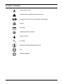
1
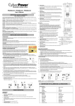
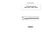
AC Power
For Business-Critical Continuity™
Liebert® PSI XR™
User Manual–1000/1500/1920/3000VA, 60Hz, 120VAC
TABLE OF CONTENTS
1.0
INTRODUCTION . . . . . . . . . . . . . . . . . . . . . . . . . . . . . . . . . . . . . . . . . . . . . . . . . . . . . . . . . .4
2.0
WHAT’S INCLUDED . . . . . . . . . . . . . . . . . . . . . . . . . . . . . . . . . . . . . . . . . . . . . . . . . . . . . . .6
3.0
INSTALLATION . . . . . . . . . . . . . . . . . . . . . . . . . . . . . . . . . . . . . . . . . . . . . . . . . . . . . . . . . .7
3.1
Preparation . . . . . . . . . . . . . . . . . . . . . . . . . . . . . . . . . . . . . . . . . . . . . . . . . . . . . . . . . . . . . . . . . 7
3.2
Tower UPS Installation . . . . . . . . . . . . . . . . . . . . . . . . . . . . . . . . . . . . . . . . . . . . . . . . . . . . . . . 8
3.3
Rack-Mount UPS Conversion and Installation . . . . . . . . . . . . . . . . . . . . . . . . . . . . . . . . . . . . 9
3.4
Orient Display for Installation . . . . . . . . . . . . . . . . . . . . . . . . . . . . . . . . . . . . . . . . . . . . . . . . 10
3.5
Connect Input Power and Load . . . . . . . . . . . . . . . . . . . . . . . . . . . . . . . . . . . . . . . . . . . . . . . . 10
3.6
Connect Network Surge protection . . . . . . . . . . . . . . . . . . . . . . . . . . . . . . . . . . . . . . . . . . . . . 11
3.7
Connect Computer Interface Port . . . . . . . . . . . . . . . . . . . . . . . . . . . . . . . . . . . . . . . . . . . . . . 11
3.8
EPO Switch. . . . . . . . . . . . . . . . . . . . . . . . . . . . . . . . . . . . . . . . . . . . . . . . . . . . . . . . . . . . . . . . 12
3.9
External Battery Cabinet Installation . . . . . . . . . . . . . . . . . . . . . . . . . . . . . . . . . . . . . . . . . . 12
4.0
CONTROLS AND INDICATORS. . . . . . . . . . . . . . . . . . . . . . . . . . . . . . . . . . . . . . . . . . . . . . . 14
4.1
Control Buttons . . . . . . . . . . . . . . . . . . . . . . . . . . . . . . . . . . . . . . . . . . . . . . . . . . . . . . . . . . . . 15
4.1.1
4.1.2
4.2
On/Alarm Silence/Manual Self-Diagnostic Test . . . . . . . . . . . . . . . . . . . . . . . . . . . . . . . . . . . . 15
Off Button . . . . . . . . . . . . . . . . . . . . . . . . . . . . . . . . . . . . . . . . . . . . . . . . . . . . . . . . . . . . . . . . . . 15
Status Indicators . . . . . . . . . . . . . . . . . . . . . . . . . . . . . . . . . . . . . . . . . . . . . . . . . . . . . . . . . . . 15
4.2.1
4.2.2
4.2.3
4.2.4
Status Change Button . . . . . . . . . . . . . . . . . . . . . . . . . . . . . . . . . . . . . . . . . . . . . . . . . . . . . . . .
Load Level Indicator. . . . . . . . . . . . . . . . . . . . . . . . . . . . . . . . . . . . . . . . . . . . . . . . . . . . . . . . . .
Battery Level Indicator . . . . . . . . . . . . . . . . . . . . . . . . . . . . . . . . . . . . . . . . . . . . . . . . . . . . . . .
UPS Status Indicators . . . . . . . . . . . . . . . . . . . . . . . . . . . . . . . . . . . . . . . . . . . . . . . . . . . . . . . .
15
15
16
16
5.0
OPERATIONAL MODES . . . . . . . . . . . . . . . . . . . . . . . . . . . . . . . . . . . . . . . . . . . . . . . . . . . 17
5.1
Normal Mode . . . . . . . . . . . . . . . . . . . . . . . . . . . . . . . . . . . . . . . . . . . . . . . . . . . . . . . . . . . . . . 17
5.2
Buck/Boost Mode . . . . . . . . . . . . . . . . . . . . . . . . . . . . . . . . . . . . . . . . . . . . . . . . . . . . . . . . . . . 17
5.3
Battery Mode . . . . . . . . . . . . . . . . . . . . . . . . . . . . . . . . . . . . . . . . . . . . . . . . . . . . . . . . . . . . . . 17
5.4
Battery Recharge Operation . . . . . . . . . . . . . . . . . . . . . . . . . . . . . . . . . . . . . . . . . . . . . . . . . . 17
6.0
COMMUNICATION . . . . . . . . . . . . . . . . . . . . . . . . . . . . . . . . . . . . . . . . . . . . . . . . . . . . . . . 18
6.1
DB-9 Connector . . . . . . . . . . . . . . . . . . . . . . . . . . . . . . . . . . . . . . . . . . . . . . . . . . . . . . . . . . . . 18
6.2
Remote Shutdown Via the DB-9 Connector . . . . . . . . . . . . . . . . . . . . . . . . . . . . . . . . . . . . . . 18
6.2.1
6.2.2
Any Mode Shutdown Via Pins 5 & 6 . . . . . . . . . . . . . . . . . . . . . . . . . . . . . . . . . . . . . . . . . . . . . 18
Battery Mode Shutdown Via Pins 4 & 5 . . . . . . . . . . . . . . . . . . . . . . . . . . . . . . . . . . . . . . . . . . 18
6.3
RJ-45 Data Line Protection Connectors . . . . . . . . . . . . . . . . . . . . . . . . . . . . . . . . . . . . . . . . . 19
6.4
UPS Communications . . . . . . . . . . . . . . . . . . . . . . . . . . . . . . . . . . . . . . . . . . . . . . . . . . . . . . . 19
6.5
UPS Inverter/Transfer Voltage Configurations . . . . . . . . . . . . . . . . . . . . . . . . . . . . . . . . . . . 19
i
7.0
BATTERY MAINTENANCE. . . . . . . . . . . . . . . . . . . . . . . . . . . . . . . . . . . . . . . . . . . . . . . . . . 20
7.1
Battery Charging, Storage . . . . . . . . . . . . . . . . . . . . . . . . . . . . . . . . . . . . . . . . . . . . . . . . . . . . 20
7.2
Internal Battery Replacement Procedure . . . . . . . . . . . . . . . . . . . . . . . . . . . . . . . . . . . . . . . . 20
8.0
SPECIFICATIONS . . . . . . . . . . . . . . . . . . . . . . . . . . . . . . . . . . . . . . . . . . . . . . . . . . . . . . . .21
9.0
TROUBLESHOOTING . . . . . . . . . . . . . . . . . . . . . . . . . . . . . . . . . . . . . . . . . . . . . . . . . . . . . 24
FIGURES
Figure 1
Figure 2
Figure 3
Figure 4
Figure 5
Figure 6
Figure 7
Figure 8
Figure 9
Figure 10
Figure 11
Figure 12
Figure 13
Figure 14
Figure 15
Figure 16
Figure 17
Figure 18
Front view of UPS, rack mount . . . . . . . . . . . . . . . . . . . . . . . . . . . . . . . . . . . . . . . . . . . . . . . . . . . . . 4
1000 and 1500VA—rear view . . . . . . . . . . . . . . . . . . . . . . . . . . . . . . . . . . . . . . . . . . . . . . . . . . . . . . . 4
1920VA—rear view . . . . . . . . . . . . . . . . . . . . . . . . . . . . . . . . . . . . . . . . . . . . . . . . . . . . . . . . . . . . . . . 5
3000VA—rear view . . . . . . . . . . . . . . . . . . . . . . . . . . . . . . . . . . . . . . . . . . . . . . . . . . . . . . . . . . . . . . . 5
Accessories. . . . . . . . . . . . . . . . . . . . . . . . . . . . . . . . . . . . . . . . . . . . . . . . . . . . . . . . . . . . . . . . . . . . . . 6
Placing the Liebert PSI XR . . . . . . . . . . . . . . . . . . . . . . . . . . . . . . . . . . . . . . . . . . . . . . . . . . . . . . . . 7
Tower configuration—attach Tower Stand . . . . . . . . . . . . . . . . . . . . . . . . . . . . . . . . . . . . . . . . . . . . 8
Convert the Liebert PSI XR for rack installation . . . . . . . . . . . . . . . . . . . . . . . . . . . . . . . . . . . . . . . 9
Adjusting the UPS display . . . . . . . . . . . . . . . . . . . . . . . . . . . . . . . . . . . . . . . . . . . . . . . . . . . . . . . . 10
Connect input power and load . . . . . . . . . . . . . . . . . . . . . . . . . . . . . . . . . . . . . . . . . . . . . . . . . . . . . 10
Connect network surge protection . . . . . . . . . . . . . . . . . . . . . . . . . . . . . . . . . . . . . . . . . . . . . . . . . . 11
Connect computer interface port . . . . . . . . . . . . . . . . . . . . . . . . . . . . . . . . . . . . . . . . . . . . . . . . . . . 11
EPO connection for normally open operation . . . . . . . . . . . . . . . . . . . . . . . . . . . . . . . . . . . . . . . . . 12
Install the external battery cabinet in tower installation . . . . . . . . . . . . . . . . . . . . . . . . . . . . . . . 12
Connect battery cabinets to UPS . . . . . . . . . . . . . . . . . . . . . . . . . . . . . . . . . . . . . . . . . . . . . . . . . . . 13
Display and status indicators. . . . . . . . . . . . . . . . . . . . . . . . . . . . . . . . . . . . . . . . . . . . . . . . . . . . . . 14
DIP switch settings for 120V system . . . . . . . . . . . . . . . . . . . . . . . . . . . . . . . . . . . . . . . . . . . . . . . . 19
Battery replacement . . . . . . . . . . . . . . . . . . . . . . . . . . . . . . . . . . . . . . . . . . . . . . . . . . . . . . . . . . . . . 20
TABLES
Table 1
Table 2
Table 3
Table 4
Table 5
Table 6
Table 7
Table 8
Table 9
Battery cabinet connector color key . . . . . . . . . . . . . . . . . . . . . . . . . . . . . . . . . . . . . . . . . . . . . . . . .
Display and status indicators function, legend . . . . . . . . . . . . . . . . . . . . . . . . . . . . . . . . . . . . . . . .
Status indicators—color, illumination mode . . . . . . . . . . . . . . . . . . . . . . . . . . . . . . . . . . . . . . . . . .
DB-9 pin assignment . . . . . . . . . . . . . . . . . . . . . . . . . . . . . . . . . . . . . . . . . . . . . . . . . . . . . . . . . . . .
Voltage configurations . . . . . . . . . . . . . . . . . . . . . . . . . . . . . . . . . . . . . . . . . . . . . . . . . . . . . . . . . . .
Liebert PSI XR specifications . . . . . . . . . . . . . . . . . . . . . . . . . . . . . . . . . . . . . . . . . . . . . . . . . . . . . .
Battery cabinet specifications . . . . . . . . . . . . . . . . . . . . . . . . . . . . . . . . . . . . . . . . . . . . . . . . . . . . .
Liebert PSI XR battery run times . . . . . . . . . . . . . . . . . . . . . . . . . . . . . . . . . . . . . . . . . . . . . . . . . .
Troubleshooting—problems, causes and solutions . . . . . . . . . . . . . . . . . . . . . . . . . . . . . . . . . . . . .
ii
12
14
16
18
19
21
22
23
24
IMPORTANT SAFETY INSTRUCTIONS
SAVE THESE INSTRUCTIONS
This manual contains important instructions that should be followed during installation and maintenance of the UPS.
• Intended for installation in a temperature-controlled, indoor area free of conductive contaminants.
• Maximum ambient temperature 104°F (40°C).
Read this manual thoroughly before attempting to install or operate this UPS.
The equipment can be installed and operated by individuals without previous training.
! WARNING
Operate the UPS only from a properly grounded (earthed) 110-127VAC, 50Hz or 60Hz AC
supply.
Some components are live, even when AC power is disconnected. For service, contact a
properly trained and qualified technician. Do not remove the cover; the UPS has no
user-serviceable parts inside except the internal battery pack.
! WARNING
Although the UPS has been designed and manufactured to ensure personal safety, improper
use can result in electrical shock or fire. To ensure safety, observe the following rules:
• Turn Off and unplug the UPS before cleaning it. Clean the UPS with a dry cloth. Do not use
liquid or aerosol cleaners.
• Do not install or operate the UPS in or near water.
• Never block or insert any objects into the ventilation holes or other openings of the UPS.
Keep all vents free of dust accumulation that could restrict air flow.
• Do not place UPS power cord anywhere it might be damaged.
Battery Handling Precautions
! WARNING
Batteries should be replaced only by properly trained and qualified personnel knowledgeable
of batteries and required precautions.
A battery can present a risk of electrical shock and high short-circuit current. The following
precautions must be observed when working on batteries:
• Remove watches, rings and other metal objects.
• Use tools with insulated handles.
• Do not dispose battery or batteries in a fire. The battery may explode.
• Do not open or mutilate the battery or batteries. Released electrolyte is toxic. It may cause
injury to the skin and eyes.
• When replacing the battery, use the same type of battery as is listed in Tables 6 and 7.
• Handle, transport and recycle batteries in accordance with local regulations.
1
ELECTROMAGNETIC COMPATIBILITY—The Liebert PSI XR complies with part 15 of the FCC
Rules. Operation is subject to the following two conditions:
• This device may not cause harmful interference, and
• This device must accept any interference received, including interference that may cause undesired operation.
This equipment uses, generates and can radiate radio frequency energy and, if not installed and used
in accordance with the instructions, may cause harmful interference with radio communications.
However, there is no guarantee that interference will not occur in a particular installation. If this
equipment does cause harmful interference to radio or television reception, the user is encouraged to
try to correct the interference by one or more of the following measures:
• Reorient or relocate the receiving antenna.
• Increase the separation between the UPS and the receiver.
• Connect the UPS to an outlet on a circuit different from the one the receiver is connected to.
The Liebert PSI XR is not intended for use with life support or other designated critical devices. Maximum load must not exceed that shown on the rating label.
NOTICE
The input receptacle must be within 10 feet (3 meters) of the UPS.
Your UPS provides conditioned power to connected equipment. Maximum load must not
exceed that shown on UPS rating label. If uncertain, consult your local dealer, Emerson
representative or Emerson Network Power Liebert Applications.
Placing magnetic storage media on top of the UPS may result in data corruption.
NOTICE
Do not connect equipment that could overload the UPS or demand half-wave rectification
from the UPS, such as electric drills, vacuum cleaners, laserjet printers and hair dryers.
2
GLOSSARY OF SYMBOLS
Risk of electrical shock
!
Indicates caution followed by important instructions
Indicates the unit contains a valve-regulated, lead-acid battery
Recycle
DC voltage
Equipment grounding conductor
Bonded to ground
AC voltage
ON/Alarm Silence/Manual Self-Diagnostic Test
OFF
Status Change Button
3
Introduction
1.0
INTRODUCTION
The Liebert PSI™ XR is a 2U, line-interactive UPS that may be installed in a rack or used as a tower
UPS.
Status indicators on the front of the Liebert PSI XR display load level, battery level, buck/boost, sitewiring fault and battery status. Controls include a combination ON/ Alarm Silence/Manual Self-Diagnostic button, an Off button and a Display Status Change button.
The Liebert PSI XR has USB, DB-9 (RS232/contact closure) and SNMP interface ports. The DB-9 and
USB ports provide detailed operating information including voltages, currents, and alarm status to
the host system when used in conjunction with Liebert MultiLink™ shutdown software.
Figure 1
Front view of UPS, rack mount
Liebert PSI XR
rack-mount configuration
Display rotates for use as tower
Liebert PSI XR
tower configuration
Display rotates for use in rack
Figure 2
1000 and 1500VA—rear view
Liebert
IntelliSlot
Port
RS232 (DB-9) Port
Input Circuit Breaker
(12A for 1000VA;
15A for 1500VA)
USB
Port
INPUT
EPO
Output Circuit Breaker
(8A for 1000VA;
15A for 1500VA)
Receptacles
NEMA 5-15R
OUTPUT
EPO
FUNCTION
VOLTAGE=110V
VOLTAGE=120V
VOLTAGE=127V
2
1
Voltage Configuration
DIP Switch
DC 24V
RJ-45 Data Line
Connectors
External Battery
Cabinet Connector
4
Power Cord; 5-15P
(not shown for clarity)
Introduction
Figure 3
1920VA—rear view
15A Output Circuit Breaker
for Receptacles #3 & #4
Power Cord; 5-20P
(not shown for clarity)
RS232 (DB-9)
Port
Liebert
IntelliSlot
Port
30A Input
Circuit Breaker
Receptacles #3 and #4
NEMA 5-15R
Receptacles #1 and #2;
NEMA 5-20R T-Slot
Receptacles
#5 and #6
NEMA 5-15R
INPUT
EPO
FUNCTION
VOLTAGE=110V
VOLTAGE=120V
VOLTAGE=127V
2
1
OUTPUT
DC 48V
EPO
External Battery
Cabinet Connector
USB Port
Voltage Configuration
DIP Switch
Figure 4
RJ-45 Data
Line Connectors
20A Input Circuit Breaker
Receptacles #1 and #2
15A Output Circuit Breaker
for Receptacles #5 & #6
3000VA—rear view
Power Cord; L5-30P
(not shown for clarity)
RS232
(DB-9)
Port
Liebert
IntelliSlot
Port
15A Output Circuit Breaker
for Receptacles #3 & #4
Receptacles #3 and #4
NEMA 5-15R
NEMA L5-30R
30A Input
Receptacle
Circuit Breaker
Receptacles #1 and #2;
NEMA 5-20R T-Slot
Receptacles
#5 and #6
NEMA 5-15R
INPUT
EPO
FUNCTION
VOLTAGE=110V
VOLTAGE=120V
VOLTAGE=127V
2
1
OUTPUT
DC 48V
EPO
USB Port
Voltage Configuration
DIP Switch
External Battery
15A Output Circuit Breaker
Cabinet Connector
RJ-45 Data
for Receptacles #5 & #6
Line Connectors
20A Output Circuit Breaker
Receptacles #1 and #2
5
What’s Included
2.0
WHAT’S INCLUDED
The Liebert PSI XR is shipped with the following items:
•
•
•
•
•
•
•
•
•
•
Figure 5
Multi-Language User Manual on CD
Liebert MultiLink Shutdown Software and User Manual on CD
DB-9 Serial Cable
USB Cable
Tower Stand
Rack-Mount Handles
Battery-UPS Tab
Mounting Hardware
Fixed Mounting Rails
EPO Connector
Accessories
Liebert Shutdown
Software Program
Liebert MultiLink
Shutdown Software &
User Manual on CD
Battery-UPS Tab
DB-9
Serial Cable
6 ft (1.8m)
USB cable
6 ft (1.8m)
Rack-Mount
Handles
Mounting Hardware
(Screws and Washers)
Fixed
Mounting Rails
Tower Stand
6
Installation
3.0
INSTALLATION
3.1
Preparation
! CAUTION
The UPS and battery cabinets are heavy (see Table 6 and Table 7). Take proper precautions
when lifting or moving either the UPS or battery cabinets.
The Liebert PSI XR may be installed in either a tower or rack configuration. Determine the method
that suits the application and proceed.
Decide where to install the Liebert PSI XR. The UPS must be installed indoors in a controlled environment. Place it in an area with unrestricted airflow around the unit, away from water, flammable
liquids, gases, corrosives and conductive contaminants (see Figure 6).
Maintain a minimum clearance of 12 inches (305mm) in the front and rear of the UPS. Maintain an
ambient temperature range of 32°F to 104°F (0°C to 40°C).
Figure 6
Placing the Liebert PSI XR
AIR
32 F (0 C)
R
AI
104 F (40 C)
AIR
5mm
0
3
/
.
12 in
Relative humidity
(non-condensing)
7
0% ~ 90%
Installation
3.2
Tower UPS Installation
See Figure 7 when using the Liebert PSI XR in a tower configuration.
Figure 7
Tower configuration—attach Tower Stand
Step 2
Step 1
8
Installation
3.3
Rack-Mount UPS Conversion and Installation
See Figure 8 when installing the Liebert PSI XR in a rack. External battery cabinets are installed in
same manner.
Figure 8
Convert the Liebert PSI XR for rack installation
Step 1
Step 2
Load Level
Battery Level
Load Level
Battery Level
Step 4
Step 3
Load Level
Battery
Level
Step 5
Load Level
Battery
Level
! WARNING
Placing heavy equipment near the top of a rack may increase the risk of tipping. Place the
UPS, and battery cabinet if one is being used, in the bottom of the rack.
! CAUTION
Lifting equipment into rack may be a two-person job, depending on weight of equipment.
NOTICE
When rack-mounted, the UPS must be supported by a shelf, slide rails, brackets or fixed rails
on each side. The rack-mount handles WILL NOT support the weight of the UPS. They are
used to move the UPS into and out of the rack.
9
Installation
3.4
Orient Display for Installation
The Liebert PSI XR features a rotating display that may be oriented for either tower or rack installations.
To set the display for your installation, pull out on the display and rotate it until it is oriented correctly, then press it into the UPS until it is seated.
Figure 9
3.5
Adjusting the UPS display
Connect Input Power and Load
Connect input power to the UPS, then plug the equipment into the outlets on the rear of the UPS.
These UPS outlets provide battery backup and surge protection to the equipment when utility power
fails, spikes or sags (see Figure 10).
Figure 10 Connect input power and load
FUNCTION
VOL TAGE=1 10 V
VOL TAGE=1 20 V
VOL TAGE=1 27 V
EPO
2
1
INPUT
OUTPUT
DC 24V
10
Installation
3.6
Connect Network Surge protection
Connect a 10 base-T/100 network cable to the RJ-45 network surge protection IN jack on the rear of
the UPS. Connect from the OUT jack with network cabling to network equipment (see Figure 11).
Figure 11
Connect network surge protection
Network
Equipment
INPUT
OUTPUT
EPO
FUNCTION
2
1
VOLTAGE=110V
VOLTAGE=120V
VOLTAGE=127V
DC 24V
Network surge
protection IN jack
3.7
Network surge
protection OUT Jack
Connect Computer Interface Port
Determine what type of communication connection to use to manage the UPS. The Liebert PSI XR
can be monitored with any of these communication methods:
•
•
•
•
serial
contact closure
USB
SNMP
Connect the appropriate, factory-supplied cable to the interface port on the rear of the UPS and to the
computer interface port. See the Liebert MultiLink shutdown software user manual on the included
CD-ROM for details and installation information. Also refer to 6.4 - UPS Communications.
Figure 12 Connect computer interface port
EPO
USB connector is to left of DB-9 port
on the UPS; USB port on computer varies
FUNCTION
VO LT AGE= 110V
VO LT AGE=120V
VO LT AGE=127V
2
1
INPUT
OUTPUT
DC 24V
11
Installation
3.8
EPO Switch
The Liebert PSI XR is equipped with an Emergency Power Off (EPO) switch. The user must supply a
means of interfacing with the EPO circuit to allow disconnecting the UPS input feeder breaker to
interrupt all sources of power to the UPS and connected equipment to comply with national and local
wiring codes and regulations.
Figure 13 EPO connection for normally open operation
1
3.9
1 = EPO+
2 = Ground
Short Pin 1 and Pin 2 to enable the EPO function
2
External Battery Cabinet Installation
Optional Liebert external battery cabinets may be connected to the UPS to provide additional battery
run time. External battery cabinets are designed to be placed all on one side of the UPS or stacked
beneath the UPS. The batteries have a maximum run time of three hours at full load.
1. Install the external battery cabinet in tower- or rack-configuration (see Figure 14 or 3.3 - RackMount UPS Conversion and Installation).
2. Connect the external battery cabinet cable to the rear of the external battery cabinet, then to the
rear of the UPS (see Figure 15).
Figure 14 Install the external battery cabinet in tower installation
Connect the top of the UPS
to the top of the battery cabinet
with the Battery UPS Tab and
hardware
If two or more battery cabinets are
used in a tower setup, the tower stand
must be extended with the spacers
included with each battery cabinet.
Connect tower stand and set
the UPS and battery cabinet in
them; check to ensure stability
NOTICE
External battery cabinet power connectors are color-coded as noted in Table 1. Do not try to
install external battery cabinets with connectors that are a different color from the battery
connector on the UPS.
Table 1
Battery cabinet connector color key
UPS Model
PS1000RT3-120XR
PS1000RT3120XRW
PS1500RT3-120XR
PS1500RT3120XRW
PS2200RT3-120XR
PS2200RT3120XRW
PS3000RT3-120XR
PS3000RT3120XRW
Nominal System Voltage (connector color)
External Battery Cabine Model
24VDC (Red)
PSRT3-24VBXR
48VDC (Gray)
PSRT3-48VBXR
12
Installation
Figure 15 Connect battery cabinets to UPS
INPUT
OUTPUT
EPO
FUNCTION
VOLTAGE=110V
VOLTAGE=120V
VOLTAGE=127V
2
1
DC 24V
See Table 8 for approximate battery run times.
13
Controls and Indicators
4.0
CONTROLS AND INDICATORS
Buttons on the front panel display control the Liebert PSI XR. Eight LEDs indicate the UPS’s status.
Refer to Figure 16 and Table 2.
Figure 16 Display and status indicators
1
2
3
4
5
Load Level
Battery Level
6
Table 2
Item
7
8
9
10
11
Display and status indicators function, legend
Name
Status Indicators
Description
1
LED 1
AVR Boost
UPS Operation in AVR Boost Mode
2
LED 2
AVR Buck
UPS Operation in AVR Buck Mode
3
LED 3
Battery Condition
Battery Fault/Weak
4
LED 4
Grounding/Site Wiring Fault
UPS Grounding/Site Wiring Fault
5
LED 5
Overload
UPS Overload
1 to 5
Load/Battery Level
Indicate Load/Battery Level
6
Status Change Button
Switches Display from Load Level Indicators
to Battery Level Indicators
7
OFF Button
UPS Off
8
ON Button
Turn on UPS, Manual Self-Diagnostic (Normal Mode),
Silence Alarm (Battery Mode)
9
LED 9
Normal Mode
UPS Operation in Normal Mode
10
LED 10
Battery Mode
UPS Operation in Battery Mode
11
LED 11
UPS Fault
UPS Fault
14
Controls and Indicators
4.1
Control Buttons
4.1.1
On/Alarm Silence/Manual Self-Diagnostic Test
This button controls output power to connected load(s). It has three functions:
• On
• Alarm Silence
• Manual Self-Diagnostic Test
ON—Start the UPS by pressing this button for more than 3 seconds, then releasing the button (an
alarm will sound briefly). If the ON button is pressed and utility is outside input parameters, the UPS
will start on battery (dark start).
Alarm Silence—Silence a battery mode audible alarm by pressing this button for longer than one
second, then releasing it.
Manual Self-Diagnostic Test—To initiate a Manual Self-Diagnostic, press this button for at least
three (3) seconds while operating from utility power. UPS will switch to Battery Mode to detect battery voltage and whether the UPS is operating normally.
If LED indicates the battery is weak: Allow the UPS to recharge the batteries for 8 hours.
Retest the battery after recharge.
If LED still indicate battery weak after the battery has been retested, contact your local
dealer, Emerson representative or Liebert Applications.
If LED indicates a Battery Fault: Contact your local dealer, Emerson representative or Liebert
Applications.
If LED indicates UPS Fault: Remove the load, retest the self diagnostic test, if LED indicated
UPS Fault, Contact your local dealer, Emerson representative or Liebert Applications.
NOTE
Refer to Figure 16 and Table 2 for details about the LEDs’ meaning.
4.1.2
Off Button
When the UPS is operating in either Normal Mode or Battery Mode, pressing the Off button for more
than three seconds will shut down the UPS.
4.2
Status Indicators
4.2.1
Status Change Button
The Status Change Button determines the information displayed by the five LEDs on the front panel.
The default information shown by the LEDs is the load level on the UPS. Pressing the Status Change
Button while the UPS is On prompts the LED display to show battery capacity for 5 seconds. This
function assists in assessing the meaning of status indicators as described in 4.2.4 - UPS Status
Indicators. See Figure 16 and Table 2 for the Status Change Button’s location.
4.2.2
Load Level Indicator
The five LEDs at the top of the front panel illuminate with a steady glow to indicate the load level on
the output of the UPS. The LEDs show the load level as a range, ± 5%. The LEDs’ load level meanings
and colors are:
LED 1
LED 2
LED 3
LED 4
LED 5
10 - 24% — Green
25 - 49% — Green
50 - 74% — Yellow
75 - 99% — Yellow
100% or greater — Red
15
Controls and Indicators
4.2.3
Battery Level Indicator
The five LEDs illuminate with a steady glow to indicate battery capacity. Battery capacity is shown
for five seconds after the Status Change Button is pressed. The LEDs show the battery capacity as a
range, ± 5% The LEDs’ battery level meanings and colors are:
4.2.4
LED 1
LED 2
LED 3
LED 4
LED 5
100 - 76% — Green
75 - 51% — Green
50 - 26% — Yellow
25 - 11% — Yellow
10% or less — Red
UPS Status Indicators
LEDs on the display panel illuminate with a steady glow or flash to indicate the UPS’s status:
Normal Mode—The Normal Mode indicator illuminates (LED 9) with a steady glow when utility
power is available and within the input specifications.
Battery Mode—The Battery Indicator illuminates (LED 10) with a steady glow when the UPS is
operating on battery
AVR Boost, AVR Buck—When the UPS is in AVR Boost/Buck Mode, the LED display will indicate
the relative load level on the output of the UPS and will flash LED 1 (boost) or LED 2 (buck) to indicate the mode.
Weak Battery—When the UPS battery voltage is low, the LED display will indicate the relative load
level on the output of the UPS and LED 3 will flash as a warning.
Site-Wiring Fault—In case of a site-wiring fault, the LED display will indicate the relative load
level on the output of the UPS and LED 4 will flash as a warning.
Overload—When UPS operates in overload status, the LED display will indicate the relative load
level on the output of the UPS and LED 5 will flash as a warning.
Table 3
Status indicators—color, illumination mode
Status
LED 1
LED 2
LED 3
LED 4
LED 5
AVR Buck
Green
Flashes
Green
Flashes
Green
Steady
Yellow
Steady
Yellow
Flashes
Yellow
Flashes
Site-Wiring Fault
Red
Flashes
Overload
Battery Fault
Shutdown
LED 11
Green
Steady
Battery Mode
(dark start)
Weak Battery
LED 10
Green
Steady
Normal Mode
AVR Boost
LED 9
Yellow
Steady
Overload
Shutdown
Red
Steady
Red
Steady
UPS Output
Abnormal
Shutdown
Red
Steady
Yellow
Steady
16
Red
Steady
Operational Modes
5.0
OPERATIONAL MODES
5.1
Normal Mode
When the UPS is in Normal Mode, the Normal Mode Indicator illuminates green.
5.2
Buck/Boost Mode
The Automatic Voltage Regulator (AVR) circuitry compensates for fluctuations in utility power, such
as voltage surges and sags. When the Liebert PSI XR detects an abnormality, it raises the undervoltage (boost) or lowers the overvoltage (buck) as needed. The AVR operates automatically and maintains the output voltage to the connected equipment, without utilizing the batteries.
LED 1 flashes green and LED 9 illuminates steady green when the UPS is in Boost Mode. LED 2
flashes green and LED 9 illuminates steady green when the UPS is in Buck Mode (see 9.0 - Troubleshooting for details).
5.3
Battery Mode
The UPS switches to Battery Mode in the event of an extreme input voltage/frequency condition or
utility failure.
When the UPS is in Battery Mode, the Battery Indicator illuminates amber and an alarm sounds at
two-second intervals. As capacity decreases, fewer indicators remain illuminated.
When a Low Battery condition occurs, the Battery Indicator flashes amber and an alarm sounds at
one-second intervals. Refer to Table 8 for approximate battery run times.
5.4
Battery Recharge Operation
Once utility power is restored, the UPS resumes normal operation and the Battery Charger begins
recharging the batteries.
17
Communication
6.0
COMMUNICATION
6.1
DB-9 Connector
The UPS has a DB-9 (9 pin female) connector on the rear to allow UPS status communications with a
computer running Liebert MultiLink shutdown software. The connection provides serial communication, On Battery and Low Battery signals. Liebert MultiLink software and a 6 ft. (1.8m) DB-9 serial
cable are shipped with the UPS.
When power is interrupted and battery power is low, Liebert MultiLink software can signal the host
computer to gracefully shut down the operating system.
Table 4
DB-9 pin assignment
DB-9 Pin
Assignment Description
1
Low Battery (open collector)
2
UPS TxD
3
UPS RxD
4
Remote Shutdown (5-12V); on-battery operation
5
Common
6
Output Off, (short to Pin 5, non-latching); any mode operation
7
Low Battery (open emitter)
8
Utility Fail (open emitter)
9
Utility Fail (open collector)
Pin Assignment
6
7
8
Collector to Emitter*
9
330 Ohms
1
6.2
2
3
4
Open
(+) Collector
(-)
5
Open
Emitter
Remote Shutdown Via the DB-9 Connector
The Liebert PSI XR can be shut down remotely by shorting Pins 5 and 6 or via Pins 4 and 5 of the DB9 connector.
6.2.1
Any Mode Shutdown Via Pins 5 & 6
When Pin 6 is shorted to Pin 5, the UPS output is shut Off no matter what mode the UPS is operating. The UPS cannot be started as long as the pins are shorted. When the short is removed, the UPS
output can be enabled by pressing the ON/Alarm Silence/Manual Self-Diagnostic button.
6.2.2
Battery Mode Shutdown Via Pins 4 & 5
While the UPS is operating on battery, a 5-12VDC signal for 2 seconds or longer is required to signal
a shutdown. Signals for less than 2 seconds are ignored.
After Pin 4 receives the shutdown signal, a 2-minute shutdown timer begins a countdown. The shutdown timer cannot be stopped: If utility power returns during the 2-minute countdown, the shutdown
timer continues until the end of 2 minutes and the UPS turns Off. The UPS will restart 10 seconds
after utility power returns.
18
Communication
6.3
RJ-45 Data Line Protection Connectors
Data line (in and out) connectors on the rear of the UPS provide transient voltage surge suppression
(TVSS) for network devices.
6.4
UPS Communications
The Liebert PSI XR is equipped with a Liebert IntelliSlot® port to provide advanced communication
and monitoring options.
Liebert MultiLink software continually monitors the UPS and can shut down your computer or server
via USB and RS-232 in the event of an extended power failure.
The Liebert IS-WEBRT3 provides SNMP and Web-based monitoring and control of the UPS across
the network.
NOTE
The USB, SNMP and contact closure communications operate in parallel. Using the Liebert
IS-WEBRT3 disables the serial communications of the DB-9.
6.5
UPS Inverter/Transfer Voltage Configurations
A two-pin DIP switch on the rear of the PSI XR permits setting the UPS to operate at nominal voltages of 110V, 120V or 127V. This feature will change the high and low points at which the UPS
switches to battery power. It also changes the UPS’ output voltage when the UPS is operating in battery mode. The factory default setting is 120 VAC.
Figure 17 DIP switch settings for 120V system
FUNCTION
1
2
Voltage = 110V
Voltage = 120V
1
Voltage = 120V
DIP ON
Voltage = 127V
Table 5
2
Voltage configurations
Setting
Input Voltage Range
Output Voltage (Battery Mode)
110
83~138
110VAC
120
90~150
120VAC
127
96~159
127VAC
19
Battery Maintenance
7.0
BATTERY MAINTENANCE
7.1
Battery Charging, Storage
The batteries are valve-regulated, nonspillable, lead acid and must be kept charged to retain their
design life. The Liebert PSI XR continuously charges the batteries when connected to the utility supply, even while the UPS is switched Off.
If the Liebert PSI XR will be stored for an extended period, Liebert recommends connecting the UPS
to input power for at least 8 hours every four to six months to keep the batteries charged.
7.2
Internal Battery Replacement Procedure
NOTICE
This UPS is equipped with internal batteries that the user can replace without shutting down
the UPS or connected loads (hot swappable). Caution must be exercised when replacing the
batteries because the load is unprotected from power fluctuations and power failures.
To replace the batteries:
1.
2.
3.
4.
5.
6.
7.
8.
9.
10.
11.
12.
13.
Remove the two screws on the left side of the front bezel.
Pull the front bezel off the UPS.
Remove the screw on the battery connectors holder.
Remove the two screws on the battery bracket.
Disconnect the two slotted, red/gray and black battery connectors.
Grasp the battery pack assembly by the handle and pull it out of the front of the UPS.
Unpack the new battery assembly, taking care not to destroy the packing.
Compare the new and old battery assemblies to make sure they are the same. If so, proceed with
replacement. If they are different, STOP and contact your local dealer, Emerson representative or
Liebert Applications.
Slide the new battery pack into the UPS.
Reattach the battery bracket with the two screws.
Reconnect the slotted, red/gray and black battery connectors.
Reinsert the screw on the battery connectors holder.
Reattach the front bezel.
Figure 18 Battery replacement
Step 1
Step 2
Load Level
Battery Level
Load Level
Battery Level
Step 3
Step 4
l
Load Leve
Level
Battery
Load Level
Battery Level
20
Specifications
8.0
SPECIFICATIONS
Table 6
Liebert PSI XR specifications
PS1000RT3-120XR PS1500RT3-120XR PS2200RT3-120XR
PS1000RT3120XRW PS1500RT3120XRW PS2200RT3120XRW
Model Number
PS3000RT3-120XR
PS3000RT3120XRW
1000VA/900W
1500VA/1350W
1920VA/1920W*
3000VA/2700W
Unit
17.3 x 19.3 x 3.5
(440 x 490.5 x 88)
17.3 x 19.3 x 3.5
(440 x 490.5 x 88)
17.3 x 27.6 x 3.5
(440 x 700.5 x 88)
17.3 x 27.6 x 3.5
(440 x 700.5 x 88)
Shipping
22 x 24.1 x 9
(560 x 612 x 228)
22 x 24.1 x 9
(560 x 612 x 228)
22 x 34.8 x 9.0
(560 x 884 x 228)
22.0 x 34.8 x 9
(560 x 884 x 228)
Unit
56 (25)
62 (28)
92 (42)
105 (48)
Shipping
64 (29)
70 (32)
101 (46)
115 (52)
Power Rating, VA/W
Dimensions, W x D x H, in (mm)
Weight, lb (kg)
Input AC Parameters
Surge Protection
570J
Voltage Range
Without Battery Operation
83 to 159 VAC (configurable)
Frequency Range
Input Power Cord,
10ft (3m) attached
Output Receptacles
45~65Hz, (±0.5Hz)
NEMA 5-15P plug
(6) NEMA 5-15R
NEMA 5-15P plug
(6) NEMA 5-15R
NEMA 5-20P plug
NEMA L5-30P plug
(4) NEMA 5-15R
(4) NEMA 5-15R
(2) NEMA 5-20R T-Slot,
(2) NEMA 5-20R T-Slot,
accepts15A Plug
accepts15A Plug
(1) NEMA L5-30R
Voltage (Normal Mode)
110/120/127 VAC (configurable)
Voltage (Battery Mode)
110/120/127 VAC; ±5% before low-battery warning
Transfer Time
4-6 ms typical
Battery Waveform
Sinewave
Battery Parameters
Type
Quantity x Voltage x Ah
Recharge Time
Valve-regulated, nonspillable, lead acid
4 x 12 x 7.2
4 x 12 x 9
8 x 12 x 7.2
8 x 12 x 9
5 hours to 90% of rated capacity, after full discharge into resistive load
Battery Backup Time
Full Load
5 minutes
Half Load
10 minutes
Environmental
Operating Temperature, °F (°C)
32 to 104 (0 to 40)
Storage Temperature, °F (°C)
5 to 104 (-15 to 40)
Relative Humidity
0% to 90%, non-condensing
Operating Altitude
Audible Noise
Up to 3000m (10,000 ft)
<40 dBA, internal fan(s) Off; <45 dBA, internal fan(s) On
Agency
*
Safety
UL 1778, c-UL Listed
Emissions
FCC Part 15, Class A
Network Surge
UL 497 B
Transportation
ISTA Procedure 1A Certification
NEC limits the input current rating of the PS2200RT3-120XR and PS2200RT3120XRW models to 80% of the input plug's rating. Up to
2200VA/1980W is available by contacting a certified electrician to change the input plug to 30A plug. Emerson Network Power assumes no
liability for damage caused by miswiring or misapplication of the input plug.
21
Specifications
Table 7
Battery cabinet specifications
Model Number
PSRT3-24VBXR
PSRT3-48VBXR
Used w/UPS Model
PS1000RT3-120XR
PS1000RT3120XRW
PS1500RT3-120XR
PS1500RT3120XRW
PS2200RT3-120XR
PS2200RT3120XRW
PS3000RT3-120XR
PS3000RT3120XRW
Dimensions, W x D x H, in (mm)
Unit
17.3 x 19.3 x 3.5 (440 x 490.5 x 88)
Shipping
22 x 26.6 x 9 (560 x 675 x 228)
Weight, lb (kg)
Unit
64 (29)
Shipping
73 (33)
Batteries
Type
Quantity x Voltage x Ah
Valve-regulated, nonspillable, lead acid
8 x 12 x 7.2
Manufacturer
8 x 12 x 7.2
CSB, YUASA or Equivalent
Environmental
Operating Temperature, °F (°C)
32 to 104 (0 to 40)
Storage Temperature, °F (°C)
5 to 104 (-15 to 40)
Relative Humidity
0% to 90%, non-condensing
Maximum Operating Altitude
10,000 ft. (3000m)
Agency
Safety
UL 1778, c-UL Listed
Emissions
FCC Part 15, Class A
Transportation
ISTA Procedure 1A Certification
22
Specifications
Table 8
Liebert PSI XR battery run times
Number of Batteries
Internal Battery
Internal Battery
+ 1 External
Battery Cabinets
Internal Battery
+ 2 External
Battery Cabinets
Internal Battery
+ 3 External
Battery Cabinets
Internal Battery
+ 4 External
Battery
Cabinets
Internal Battery
+ 5 External
Battery Cabinets
Internal Battery
+ 6 External
Battery Cabinets
Load %
1000VA
1500VA
1920VA
3000VA
10
82
81
76
75
25
43
32
32
32
50
15
13
14
13
75
9
8
8
8
100
6
5
5
5
10
272
222
161
142
25
139
109
80
70
50
73
55
45
31
75
51
31
25
17
100
31
18
15
12
10
438
357
241
205
25
231
175
128
106
50
129
95
67
56
75
84
61
47
31
100
65
46
29
18
10
614
492
322
267
25
324
241
170
139
50
181
131
95
73
75
126
84
62
50
100
96
64
48
31
10
789
627
483
329
25
385
308
255
171
50
233
167
143
95
75
162
114
100
62
100
124
82
72
47
10
964
762
564
392
25
509
374
298
204
50
285
203
167
113
75
197
139
116
74
100
151
106
84
56
10
1140
897
644
454
25
601
440
341
236
50
336
239
191
131
75
233
163
133
85
100
179
124
102
65
Run times are in minutes, assume fully charged batteries and are typical at 77°F (25°C) with resistive loads.
23
Troubleshooting
9.0
TROUBLESHOOTING
The information below indicates various symptoms a user may encounter if the Liebert PSI XR experiences a problem. See Table 9 for suggested solutions.
1. An alarm sounds, alerting that the UPS requires attention. The alarm can be silenced except for
low battery, overload warning and fault.
2. One or more additional indicators will be illuminated to provide a diagnostic aid to the operator,
as described below:
If the UPS fails to operate properly, turn Off the unit and repeat the steps in 3.0 - Installation. If the
problem persists, refer to Table 9.
Table 9
Troubleshooting—problems, causes and solutions
Problem
Cause
Short circuit
UPS will not start
Battery is disconnected or
completely discharged
UPS not plugged in
UPS starts on battery, but will not
switch to AC (dark start)
Circuit breaker tripped
AC overvoltage
Short circuit or UPS output is
abnormal; LED 10 and LED 11
illuminate and sound audible
alarm
UPS shuts down
Overload; LED 5 and LED 11
illuminate and sound audible
alarm
LED 3 and LED 11 illuminate and
sound audible alarm
Liebert MultiLink shutdown
software
Site Wiring Fault LED (LED 4) flashing
Battery weak LED (LED 3) flashing
Site Wiring Fault, UPS detected a
line-to-neutral reversal or a loss of
proper grounding.
Batteries weak
Batteries need to be replaced
Solution
Check the circuit breaker on the
rear of the UPS.
If it is tripped, reset it and restart the
UPS. For help, contact your local
dealer, Emerson representative or
Liebert Applications.
Check for proper connection of
battery or batteries.
Plug in the power cord securely.
Reset the circuit breaker and restart
the UPS.
Wait until voltage drops to an
appropriate level or have the utility
power checked by a properly
trained and qualified electrician.
Remove the load and turn on the
UPS again. For help, contact your
local dealer, Emerson
representative or Liebert
Applications.
Check load level display and
remove nonessential loads.
Recalculate the load and reduce
equipment connected to UPS - the
total wattage must not exceed the
capacity of the UPS.
Recharge the battery for 8 hours,
then turn ON the UPS.
Consult the Liebert MultiLink
software user manual or contact
your LAN administrator.
Have the utility checked by a
properly trained and qualified
electrician.
Recharge batteries.
Replace batteries.
NOTE
The 1920VA UPS will sound an Overload alarm under certain Low Line conditions when it is
fully loaded and it exceeds the input current rating. Unless the load is reduced, the condition
will trip the branch circuit breaker.
24
Troubleshooting
Notes
25
Troubleshooting
26
Ensuring The High Availability
Of Mission-Critical Data And Applications.
Emerson Network Power, the global leader in enabling business-critical
continuity, ensures network resiliency and adaptability through
a family of technologies—including Liebert power and cooling
technologies—that protect and support business-critical systems.
Liebert solutions employ an adaptive architecture that responds
to changes in criticality, density and capacity. Enterprises benefit
from greater IT system availability, operational flexibility and
reduced capital equipment and operating costs.
Technical Support / Service
Web Site
www.liebert.com
Monitoring
800-222-5877
[email protected]
Outside the US: 614-841-6755
Single-Phase UPS
800-222-5877
[email protected]
Outside the US: 614-841-6755
Three-Phase UPS
800-543-2378
[email protected]
Environmental Systems
800-543-2778
Outside the United States
614-888-0246
Locations
United States
1050 Dearborn Drive
P.O. Box 29186
Columbus, OH 43229
Europe
Via Leonardo Da Vinci 8
Zona Industriale Tognana
35028 Piove Di Sacco (PD) Italy
+39 049 9719 111
Fax: +39 049 5841 257
Asia
7/F, Dah Sing Financial Centre
108 Gloucester Road, Wanchai
Hong Kong
852 2572220
Fax: 852 28029250
While every precaution has been taken to ensure the accuracy
and completeness of this literature, Liebert Corporation assumes no
responsibility and disclaims all liability for damages resulting from use of
this information or for any errors or omissions.
© 2008 Liebert Corporation
All rights reserved throughout the world. Specifications subject to change
without notice.
® Liebert is a registered trademark of Liebert Corporation.
All names referred to are trademarks
or registered trademarks of their respective owners.
SL-23315_REV02_08-08
Emerson Network Power.
The global leader in enabling Business-Critical Continuity.
AC Power
Embedded Computing
Embedded Power
Connectivity
DC Power
Monitoring
EmersonNetworkPower.com
Outside Plant
Power Switching & Controls
Racks & Integrated Cabinets
Services
Precision Cooling
Surge Protection
Business-Critical Continuity, Emerson Network Power and the Emerson Network Power logo are trademarks and service marks of Emerson Electric Co.
©2008 Emerson Electric Co.