1
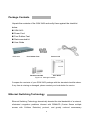
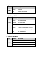
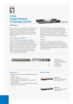
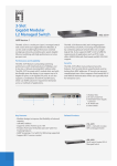
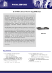
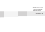
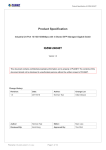
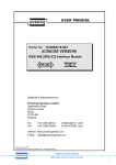
GSW-2453 Gigabit Chassis switch User Guide Contents 1. INTRODUCTION ......................................................................................................1 Features .......................................................................................................................1 Package Contents ........................................................................................................2 Ethernet Switching Technology ....................................................................................2 2. HARDWARE DESCRIPTION ...................................................................................4 Physical Dimension ......................................................................................................4 Front Panel ...................................................................................................................4 LED Indicators ..............................................................................................................4 Rear Panel....................................................................................................................6 Desktop Installation ......................................................................................................6 Rack-mounted Installation ............................................................................................6 3. NETWORK APPLICATION ......................................................................................8 4. TROUBLESHOOTING .............................................................................................9 5. TECHNICAL SPECIFICATION ..............................................................................11 1. Introduction GSW-2453, 3-slot Gigabit Chassis switch, is a modular Switch that can be used to build high-performance switched workgroup networks. This switch is a store-and-forward device that offers low latency for high-speed networking. The Switch is targeted at workgroup, department or backbone computing environment. GSW-2453 features a “store-and-forward “ switching scheme. This allows the switch to auto-learn and store source address in an 4K-entry MAC address table. MDI (Medium Dependent Interface) Port is also called an "uplink port". The MDI port does not cross transmit and receive lines, which is done by the regular ports (MDI-X ports) that connect to end stations. In general, MDI means connecting to another Hub or Switch while MDIX means connecting to a workstation or PC. Therefore, Auto MDI/MDIX means that you can connect to another Switch or workstation without changing non-crossover or crossover cabling. GSW-2453 has 3-module slot. User can accord their needs to purchase the modules. This can give elasticity on network application. Features Compatible with IEEE 802.3 10Base-T, IEEE802.3u 100Base-TX, IEEE802.3z gigabit fiber and IEEE802.3ab 1000Base-T Support 8 port gigabit 10/100/1000Tx module, 8 port Mini GBIC module, 4 port 10/100/1000TX + 4 port Mini GBIC module IEEE802.3x flow control ¾ Pause frame for 10/100/1000Mbps full duplex ¾ Backpressure for 10/100 Mbps half duplex 10Kbytes Jumbo packet support Store and forward architecture 19 inch Rack mount design 1 Package Contents Unpack the contents of the GSW-2453 and verify them against the checklist below. GSW-2453 Power Cord Four Rubber Feet Rack-mounted kit User Guide GSW-2453 Four Rubber Feet Power Cord Rack-mounted Kit User Guide Figure 1-2. Package Contents Compare the contents of your GSW-2453 package with the standard checklist above. If any item is missing or damaged, please contact your local dealer for service. Ethernet Switching Technology Ethernet Switching Technology dramatically boosted the total bandwidth of a network, eliminated congestion problems inherent with CSMA/CD (Carrier Sense multiple access with Collision Detection) protocol, and greatly reduced unnecessary 2 transmissions. This revolutionized networking. First, by allowing two-way, simultaneous transmissions over the same port (Full-duplex), which essentially doubled the bandwidth. Second, by reducing the collision domain to a single switch-port, which eliminated the need for carrier sensing. Third, by using the store-and-forward technology’s approach of inspecting each packet to intercept corrupt or redundant data, switching eliminated unnecessary transmission that slow the network. By employing address learning, which replaced the inefficient receiving port. Auto-negotiation regulates the speed and duplex of each port, based on the capability of both devices. Flow-control allows transmission from a 1000Mbps node to a 100Mbps node without loss of data. Auto-negotiation and flow-control may require disablement for some networking operations involves legacy equipment. Disabling the auto-negotiation is accomplished by fixing the speed or duplex of a port. Ethernet Switching Technology supplied higher performance at costs lower than other solutions. Wider bandwidth, no congestion, and the reduction in traffic is why switching is replacing expensive routers and inefficient hubs as the ultimate networking solution. Switching brought a whole new way of thinking to networking. 3 2. Hardware Description This Section mainly describes the hardware of the GSW-2453, and gives a physical and functional overview of this chassis switch. Physical Dimension The GSW-2453 physical dimension is 440mm(W) x 224mm(D) x 44mm(H). Front Panel The Front Panel of the GSW-2453 consists of 3 module slots. Figure 2-1 The Front Panel of the GSW-2453 The modules in the picture are optional, not including in the package. LED Indicators The LED Indicators gives real-time information of systematic operation status. The LED indicators are located in each module. The LED indicators will be different for different type of module. The following table provides descriptions of LED status and their meaning. 4 System LED Status Description Green Power On Off Power is not connected Power Gigabit Copper Module LED 1000/100 LK/ACT Status Description Green In 1000Mpbs speed Orange In 100Mbps speed Off In 10Mbps or no device is connected. Green The port is connecting with the device. Blinks The port is receiving or transmitting data. Off No device attached. Gigabit Mini GBIC Module LED LK/ACT Status Description Green The port is connecting with the device. Blinks The port is receiving or transmitting data. Off No device attached. 5 Rear Panel The 3-pronged power plug, 2 fans, power switching is located at the rear panel of the GSW-2453 as shown in Figure 2-2. The switch will work with AC power in the range of 100-240V AC, 50-60Hz. Figure 2-2. The Rear Panel of the 3-slot Gigabit Cassis switch Desktop Installation Set the Switch on a sufficiently large flat space with a power outlet nearby. The surface where you put your Switch should be clean, smooth, level and sturdy. Make sure there is enough clearance around the Switch to allow attachment of cables, power cord and allow air circulation. Attaching Rubber Feet A. Make sure mounting surface on the bottom of the Switch is grease and dust free. B. Remove adhesive backing from your Rubber Feet. C. Apply the Rubber Feet to each corner on the bottom of the Switch. These footpads can prevent the Switch from shock/vibration. Rack-mounted Installation The switch come with a rack-mounted kit and can be mounted in an EIA standard size, 19-inch Rack. The Switch can be placed in a wiring closet with other equipment. Perform the following steps to rack mount the switch: 6 A. Position one bracket to align with the holes on one side of the switch and secure it with the smaller bracket screws. Then attach the remaining bracket to the other side of the Switch. B. After attached both mounting brackets, position the switch in the rack by lining up the holes in the brackets with the appropriate holes on the rack. Secure the Switch to the rack with a screwdriver and the rack-mounting screws. Note: For proper ventilation, allow about at least 4 inches (10 cm) of clearance on the front and 3.4 inches (8 cm) on the back of the Switch. This is especially important for enclosed rack installation. Power On Connect the power cord to the power socket on the rear panel of the Switch. The other side of power cord connects to the power outlet. The internal power supply of the Switch works with voltage range of AC power in the 100-240VAC, frequency 50~60Hz. Check the power indicator on the front panel to see if power is properly supplied. 7 3. Network Application GSW-2453 is designed as a segment switch. That is, with its large address table (4000 MAC address) and high performance, it is ideal for interconnecting networking segments. PC, workstations, and servers can communicate each other by directly connecting with 3-slot Gigabit Chassis s switch. The switch automatically learns nodes address, which are subsequently used to filter and forward all traffic based on the destination address. . By using Gigabit or Gigabit Fiber the switch can connect with another switch or hub to interconnect other small-switched workgroups to form a larger switched network. Meanwhile, you can also use Ethernet or Gigabit fiber ports to connect switches. 8 4. Troubleshooting This section is intended to help you solve the most common problems on the GSW-2453. Incorrect connections The switch port can auto detect straight or crossover cable when you link switch with other Ethernet device. For the UTP connector should use correct UTP or STP cable, 10/100Mbps port use 2 pairs twisted cable and Gigabit 1000T port use 4 pairs twisted cable. If the UTP connector is not correct pin on right position then the link will fail. For fiber connection, please notice that fiber cable mode and fiber module should be match. Faulty or loose cables Look for loose or obviously faulty connections. If they appear to be OK, make sure the connections are snug. IF that does not correct the problem, try a different cable. Non-standard cables Non-standard and miss-wired cables may cause numerous network collisions and other network problem, and can seriously impair network performance. A category 5-cable tester is a recommended tool for every 100Base-T network installation. Improper Network Topologies It is important to make sure that you have a valid network topology. Common topology faults include excessive cable length and too many repeaters (hubs) between end nodes. In addition, you should make sure that your network topology contains no data path loops. Between any two ends nodes, there should be only one active cabling path 9 at any time. Data path loops will cause broadcast storms that will severely impact your network performance. Diagnosing LED Indicators The Switch can be easily monitored through panel indicators to assist in identifying problems, which describes common problems you may encounter and where you can find possible solutions. IF the power indicator does turn on when the power cord is plugged in, you may have a problem with power outlet, or power cord. However, if the Switch powers off after running for a while check for loose power connections, power losses or surges at power outlet. IF you still cannot resolve the problem, contact your local dealer for assistance. Cabling UTP ports use unshielded twisted-pair (UTP) or shield twisted-pair ( STP ) cable for RJ-45 connections: 100Ω Category 3, 4 or 5 cable for 10Mbps connections or 100Ω Category 5 cable for 100Mbps connections. Also be sure that the length of any twisted-pair connection does not exceed 100 meters (328 feet). Gigabit port should use Cat-5 or cat-5e cable for 1000Mbps connections. The length does not exceed 100 meters. 10 5. Technical Specification This section provides the specifications of the GSW-2453 and the following table lists these specifications. IEEE802.3 10Base-T Standard IEEE802.3u 100Base-TX IEEE802.3z Gigabit fiber IEEE802.3ab 1000Base-T Switch architecture Store and forward switch architecture System: Power LED Indicators Per RJ-45 port: 1000/100Mbps, Link/Activity, Full duplex/ collision Gigabit SX/LX/MINI GBIC slot: Link/Activity Gigabit copper: RJ-45 with Auto MID/MDI-X Connector Gigabit Fiber: SC MINI GBIC: LC (3.3 V type) 14880 Packets per Second for 10Mbps Transfer Rate 148800 Packets per second for 100Mbps 1488000 Packets per second for 1000Mbps 10Base-T: 2 pairs UTP/STP CAT.3, 4, 5 cable EIA/TIA 568 100Ohm(100M) Network Cable 100Base-TX: 2 pairs UTP/STP CAT. 5 cable EIA/TIA 568 100Ohm(100M) Gigabit Copper: 4 pairs UTP/STP CAT. 5 or CAT. 5e cable EIA/TIA 568 100Ohm(100M) 11 8-port Gigabit copper module(MDU-2453T) Expansion module 8 MINI GBIC module (MDU-2453M) 4 Gigabit copper+4 MiniGBIC module (MDU-2453TM) MAC address 4K Packet Buffer 2 Mbits Dimensions 440mm(W) x 224mm(D) x 44mm(H) Power Supply 100~240VAC, 50 /60Hz, 0.8A (maximum) Ventilation 2 x DC cooling fan Operating temperature -5℃~55℃, 10%~95%RH Storage temperature -40℃~70℃, 95% RH EMI FCC Class A, CE Safety UL, cUL, CE/EN60950 12