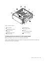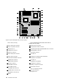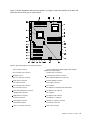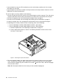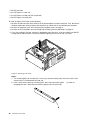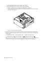
1
ThinkStation
User Guide
Machine Types: 4262, 4263, 4264, 4265, 4266, 4269, 4271, and 4272
Note: Before using this information and the product it supports, be sure to read and understand the
ThinkStation Safety and Warranty Guide and Appendix B “Notices” on page 73.
Third Edition (December 2011)
© Copyright Lenovo 2010, 2011.
LIMITED AND RESTRICTED RIGHTS NOTICE: If data or software is delivered pursuant a General Services Administration
“GSA” contract, use, reproduction, or disclosure is subject to restrictions set forth in Contract No. GS-35F-05925.
Contents
Important safety information . . . . .
iii
Chapter 1. Product overview . . . . . . 1
Features . . . . . . . . . . . . . . . . .
Specifications . . . . . . . . . . . . . . .
Software overview . . . . . . . . . . . . .
Software provided with your Windows
operating system . . . . . . . . . . . .
Locating computer controls, connectors, and
parts . . . . . . . . . . . . . . . . . .
Locating controls and connectors on the front
of your computer . . . . . . . . . . . .
Locating connectors on the rear of your
computer . . . . . . . . . . . . . . .
Locating components . . . . . . . . . .
Locating parts and connectors on the system
board . . . . . . . . . . . . . . . .
Chapter 2. Installing or replacing
hardware . . . . . . . . . . . . . . .
Installing or replacing hardware . . . . . .
Installing external options . . . . . .
Removing the computer cover. . . . .
Removing and reinstalling the front bezel
Removing and reinstalling the PCI card
holder . . . . . . . . . . . . . .
Installing or replacing a memory module .
Installing or replacing a PCI card . . . .
Installing a new hard disk drive . . . .
Replacing a hard disk drive . . . . . .
Replacing the optical drive . . . . . .
Replacing the heat sink and fan assembly
Replacing the front fan assembly . . .
Replacing the rear fan assembly . . . .
Replacing the keyboard or mouse . . .
Completing the parts replacement . . .
Obtaining device drivers . . . . . . . . .
Basic security features . . . . . . . . .
Locking devices . . . . . . . . . .
Password protection . . . . . . . .
.
.
.
1
3
4
.
4
.
6
.
6
.
.
7
8
.
9
13
.
.
.
.
.
.
.
.
13
13
13
14
.
.
.
.
.
.
.
.
.
.
.
.
.
.
.
.
.
.
.
.
.
.
.
.
.
.
.
.
.
.
15
17
21
23
26
27
29
32
34
36
37
38
38
39
40
Chapter 3. Recovery information . . .
41
Creating and using recovery media . . .
Creating recovery media . . . . . .
Using recovery media . . . . . . .
Performing backup and recovery operations
Performing a backup operation . . .
Performing a recovery operation . . .
© Copyright Lenovo 2010, 2011
.
.
.
.
.
.
.
.
.
.
.
.
.
.
.
.
.
.
41
41
41
42
43
43
Using the Rescue and Recovery workspace
Creating and using a rescue medium . . .
Creating a rescue medium . . . . .
Using a rescue medium . . . . . .
Installing or reinstalling device drivers . .
Solving recovery problems . . . . . . .
.
.
.
.
.
.
.
.
.
.
.
.
44
45
45
45
46
46
Chapter 4. Using the Setup Utility
program . . . . . . . . . . . . . . . .
49
Starting the Setup Utility program . . . . .
Viewing or changing settings . . . . . . .
Using passwords. . . . . . . . . . . .
Password considerations . . . . . . .
Administrator password . . . . . . .
User Password . . . . . . . . . . .
Setting, changing, or deleting a password
Enabling or disabling a device . . . . . .
Selecting a startup device . . . . . . . .
Selecting a temporary startup device . .
Viewing or changing the startup device
sequence . . . . . . . . . . . . .
Advanced settings . . . . . . . . . . .
Exiting the Setup Utility program . . . . .
.
.
.
.
.
.
.
.
.
.
.
.
.
.
.
.
.
.
.
.
.
.
.
.
.
.
49
49
49
50
50
50
50
50
51
51
. .
. .
. .
51
52
52
Chapter 5. Configuring RAID . . . . .
53
Configuring RAID for machine types 4262, 4263,
4264, and 4265 . . . . . . . . . . . . . .
Installing SATA hard disk drives . . . . . .
Configuring the system BIOS to enable SATA
RAID functionality. . . . . . . . . . . .
Creating RAID volumes . . . . . . . . .
Deleting RAID volumes . . . . . . . . .
Configuring RAID for machine types 4266, 4269,
4271, and 4272 . . . . . . . . . . . . . .
Installing SATA or SAS hard disk drives . . .
Entering the Marvell BIOS Setup to configure
SATA or SAS RAID . . . . . . . . . . .
Configuring the Marvell BIOS Setup to enable
SATA/SAS RAID 0, 1, or 5 functionality . . .
Configuring the Marvell BIOS Setup to set an
optional hot spare hard disk drive . . . . .
Configuring the Marvell BIOS Setup to delete
an optional hot spare hard disk drive . . . .
Configuring the Marvell BIOS Setup to delete
an array . . . . . . . . . . . . . . .
53
53
53
54
54
54
55
55
55
56
56
56
Chapter 6. Updating system
programs . . . . . . . . . . . . . . .
57
Using system programs . . . . . . . . . . .
57
i
Updating (flashing) the BIOS from a disc . . . .
Updating (flashing) the BIOS from your operating
system . . . . . . . . . . . . . . . . . .
Recovering from a POST/BIOS update failure . .
58
58
Chapter 7. Troubleshooting and
diagnostic programs . . . . . . . . .
61
Basic troubleshooting . . . . . . . .
Diagnostic programs . . . . . . . .
Lenovo Solution Center . . . . .
Lenovo ThinkVantage Toolbox . . .
PC-Doctor for Rescue and Recovery
PC-Doctor for DOS . . . . . . .
Cleaning an optical mouse . . . . . .
.
.
.
.
.
.
.
.
.
.
.
.
.
.
.
.
.
.
.
.
.
.
.
.
.
.
.
.
57
61
62
62
62
63
63
64
Lenovo ThinkVantage Tools . . . . . .
Lenovo Welcome . . . . . . . . . .
Safety and warranty . . . . . . . . .
Lenovo Web site (http://www.lenovo.com)
Help and service . . . . . . . . . . . .
Using the documentation and diagnostic
programs . . . . . . . . . . . . .
Calling for service. . . . . . . . . .
Using other services . . . . . . . .
Purchasing additional services . . . .
.
.
.
.
.
.
.
.
.
.
65
65
66
66
66
.
.
.
.
.
.
.
.
66
66
67
68
Appendix A. System memory speed .
69
Appendix B. Notices. . . . . . . . . .
73
74
74
74
75
Chapter 8. Getting information, help,
and service . . . . . . . . . . . . . .
65
Television output notice . . . . . . . . . . .
European conformance CE mark . . . . . . .
Trademarks . . . . . . . . . . . . . . . .
Information resources . . . . . . . . . . . .
Online Books folder . . . . . . . . . . .
65
65
Index. . . . . . . . . . . . . . . . . .
ii
ThinkStation User Guide
Important safety information
CAUTION:
Before using this manual, be sure to read and understand all the related safety information for this
product. Refer to the ThinkStation Safety and Warranty Guide that you received with this product for
the latest safety information. Reading and understanding this safety information reduces the risk of
personal injury and or damage to your product.
If you no longer have a copy of the ThinkCentre Safety and Warranty Guide, you can obtain a Portable
Document Format (PDF) version from the Lenovo® Support Web site at http://support.lenovo.com.
© Copyright Lenovo 2010, 2011
iii
iv
ThinkStation User Guide
Chapter 1. Product overview
This chapter provides information about the computer features, specifications, preinstalled software
programs, and connector and part locations.
This chapter contains the following topics:
•
“Features” on page 1: This section provides information about the computer features.
•
“Specifications” on page 3: This section lists the physical specifications for your computer.
•
“Software overview” on page 4: This section provides information about the software programs provided
with your computer.
•
“Locating computer controls, connectors, and parts” on page 6: This section provides information to
help you locate your computer controls, connectors, and parts.
Features
This section provides information about the computer features.
System information
The following information covers a variety of models. For information about your specific model, use the
Setup Utility program. See Chapter 4 “Using the Setup Utility program” on page 49.
Microprocessor
Your computer comes with one of the following microprocessors (internal cache size varies by model type):
• Intel® Xeon® Dual Core microprocessor
• Intel Xeon Quad Core microprocessor
• Intel Xeon Six Core microprocessor
Memory module(s)
• Supports up to six or 12 double data rate 3 dual inline memory modules (DDR3 DIMMs)
• Each microprocessor supports up to three or six memory modules
Note: The Intel Xeon microprocessor families compatible with this ThinkStation™ computer feature an
integrated memory controller, which provides the microprocessor with direct access to the system memory.
Because of this design, the system memory speed will be determined by a number of factors, including
the microprocessor model and the type, speed, size (capacity), and number of DIMMs installed. Refer to
Appendix A “System memory speed” on page 69 for the information on the supported system memory
speed for your computer model.
Internal drives
• One Serial Advanced Technology Attachment (SATA) optical drive
• Three SATA hard disk drives or Serial Attached SCSI (SAS) hard disk drives
Video subsystem
• Two Peripheral Component Interconnect (PCI) Express x16 card slots on the system board for discrete
graphics cards (varies by model type)
© Copyright Lenovo 2010, 2011
1
Audio subsystem
• Integrated high-definition (HD) audio
• Microphone connector and headphone connector on the front panel
• Eight audio connectors on the rear panel
– Audio line-in connector
– Audio line-out front speaker connector
– Audio line-out rear speaker connector
– Audio line-out side speaker connector
– Audio line-out subwoofer/center speaker connector
– Microphone connector
– Optical Sony Philips Digital Interconnect Format (SPDIF) in connector
– Optical SPDIF out connector
• Internal speakers
Connectivity
• One or two 10/100/1000 Mbps Ethernet controller(s)
System management features
• Ability to store the power-on self-test (POST) hardware test results
• Advanced Configuration and Power Interface (ACPI) support
• Alert Standard Format (ASF) 2.0
• Automatic power-on startup
• Preboot Execution Environment (PXE)
• System Management (SM) Basic Input/Output System (BIOS) and SM software
• Wake on LAN
• Wake on Ring (in the Setup Utility program, this feature is called Serial Port Ring Detect for an external
modem)
• Windows Management Instrumentation (WMI)
Input/Output (I/O) features
• 9-pin serial port (available on some models)
• 10 USB (Universal Serial Bus) connectors
• Eight audio connectors on the rear panel
• One external Serial Advanced Technology Attachment (eSATA) connector
• One or two Ethernet connector(s)
• Two audio connectors on the front panel (microphone connector and headphone connector)
• Two IEEE 1394 connectors (available on some models)
For more information about I/O features, see “Locating connectors on the rear of your computer” on page 7.
Expansion
• One optical drive bay
• One PCI Express x1 card slot
2
ThinkStation User Guide
• One PCI Express x4 card slot (x16 mechanical)
• Three hard disk drives
• Two PCI card slots
• Two PCI Express x16 card slots
Power supply
• 800-watt auto-sensing power supply
Security features
• Cover presence switch (also called intrusion switch) (available in some models)
• Enabling or disabling SATA devices
• Enabling or disabling the serial port
• Enabling or disabling USB connectors individually
• User password and administrator password to deter unauthorized use of your computer
• Startup sequence control
• Startup without keyboard or mouse
• Support for a keylock
• Support for the addition of a padlock
• Support for the addition of an integrated cable lock (Kensington lock)
• Trusted Platform Module (TPM)
Preinstalled software programs
Your computer is preinstalled with some software programs to help you work more easily and securely. For
more information, see “Software overview” on page 4.
Preinstalled operating system
Your computer is preinstalled with one of the following operating systems:
• Microsoft® Windows® 7
• Microsoft Windows XP Professional (preinstalled through downgrade rights in Windows 7 Professional)
Operating system(s), certified or tested for compatibility1 (varies by model type)
• Linux®
Specifications
This section lists the physical specifications for your computer.
1.
The operating system(s) listed here are being certified or tested for compatibility at the time this publication goes to
press. Additional operating systems might be identified by Lenovo as compatible with your computer following the
publication of this manual. This list is subject to change. To determine if an operating system has been certified or
tested for compatibility, check the Web site of the operating system vendor.
Chapter 1. Product overview
3
Dimensions
Width: 130 mm (5.12 inches)
Height: 427 mm (16.81 inches)
Depth: 444 mm (17.48 inches)
Weight
Maximum configuration: 18.5 kg (40.8 lbs)
Environment
• Air temperature:
Operating: 10°C to 35°C (50°F to 95°F)
Storage: -10°C to 60°C (14°F to 140°F) without package
• Humidity:
Operating: 10% to 80% (10% per hour, non-condensing)
Storage: 10% to 90% (10% per hour, non-condensing)
• Maximum altitude: 7 000 ft (2 133.6 m)
Electrical input
• Input voltage:
– Low range:
Minimum: 100 V ac
Maximum: 127 V ac
Input frequency range: 50 to 60 Hz
– High range:
Minimum: 200 V ac
Maximum: 240 V ac
Input frequency range: 50 to 60 Hz
Software overview
The computer comes with a preinstalled operating system and several preinstalled applications.
Software provided with your Windows operating system
This section provides information about the software provided with your Windows operating system.
Software provided by Lenovo
The following software programs are provided by Lenovo to help you improve productivity and reduce the
cost associated with maintaining your computer. Software programs provided with your computer might
vary depending on your model type and preinstalled operating system.
Notes: The following software programs are supported on your ThinkStation computer. You can find detailed
information and download the software programs from the Lenovo Support Web site at:
http://support.lenovo.com
• ThinkVantage Productivity Center
• ThinkVantage Client Security Solution (CSS)
• ThinkVantage System Update (TVSU)
4
ThinkStation User Guide
Lenovo ThinkVantage Tools
The Lenovo ThinkVantage® Tools program guides you to a host of information sources and provides easy
access to various tools to help you work more easily and securely. For more information, see “Lenovo
ThinkVantage Tools” on page 65.
Note: The Lenovo ThinkVantage Tools program is only available on computers with the Windows 7 operating
system from Lenovo.
Lenovo Welcome
The Lenovo Welcome program introduces some innovative built-in features of Lenovo to you and guides you
through some important setup tasks to help you make the most of your computer.
Note: The Lenovo Welcome program is only available on computers preinstalled with the Windows 7
operating system from Lenovo.
Product Recovery
The Product Recovery program enables you to restore the contents of the hard disk drive to the factory
default settings.
ThinkVantage Rescue and Recovery
The ThinkVantage Rescue and Recovery program is a one button recovery and restore solution that includes
a set of self-recovery tools to help you diagnose computer problems, get help, and recover from system
crashes, even if you cannot start the Windows operating system.
Lenovo Solution Center
Note: Depending on the date when your computer was manufactured, your computer is preinstalled with
either the Lenovo Solution Center program or the Lenovo ThinkVantage Toolbox program for diagnostic
purposes. For additional information about the Lenovo ThinkVantage Toolbox program, see “Lenovo
ThinkVantage Toolbox” on page 62.
The Lenovo Solution Center program enables you to troubleshoot and resolve computer problems. It
combines diagnostic tests, system information collection, security status, and support information, along
with hints and tips for maximum system performance. See “Lenovo Solution Center” on page 62 for detailed
information.
Lenovo ThinkVantage Toolbox
Note: Depending on the date when your computer was manufactured, your computer is preinstalled with
either the Lenovo Solution Center program or the Lenovo ThinkVantage Toolbox program for diagnostic
purposes. For additional information about the Lenovo Solution Center program, see “Lenovo Solution
Center” on page 62.
The Lenovo ThinkVantage Toolbox program helps you maintain your computer, improve computing security,
diagnose computer problems, get familiar with the innovative technologies provided by Lenovo, and get more
information about your computer. For more information, see “Lenovo ThinkVantage Toolbox” on page 62.
PC-Doctor for Rescue and Recovery
The PC-Doctor for Rescue and Recovery diagnostic program is preinstalled on your ThinkStation computer
as part of the Rescue and Recovery workspace to help you diagnose hardware problems. It can also report
operating-system-controlled settings that interfere with the correct operation of your system. Use the
PC-Doctor for Rescue and Recovery diagnostic program if you are unable to start the Windows operating
system. For more information, see “PC-Doctor for Rescue and Recovery” on page 63.
Adobe Reader
The Adobe Reader program is a tool used to view, print, and search PDF documents.
Chapter 1. Product overview
5
See “Online Books folder” on page 65 for more information about accessing and viewing the publications.
Antivirus software
Your computer comes with antivirus software that you can use to detect and eliminate viruses. Lenovo
provides a full version of antivirus software on your computer with a free 30-day subscription. After 30 days,
you must renew the license to continue receiving the antivirus software updates.
For more information about how to use your antivirus software, refer to the help system of your antivirus
software.
Locating computer controls, connectors, and parts
This section provides information to help you locate your computer controls, connectors, and parts.
Locating controls and connectors on the front of your computer
Figure 1 “Front control and connector locations” on page 6 shows the locations of the controls and
connectors on the front of your computer.
Figure 1. Front control and connector locations
6
1 Hard disk drive activity indicator
5 Headphone connector
2 Power switch and power indicator
6 USB connector
3 USB connector
7 IEEE 1394 connector (available on some models)
4 Microphone connector
8 Optical drive eject button
ThinkStation User Guide
Locating connectors on the rear of your computer
Figure 2 “Rear connector locations” on page 7 shows the locations of the connectors on the rear of your
computer. Some connectors on the rear of your computer are color-coded to help you determine where to
connect the cables on your computer.
Figure 2. Rear connector locations
1 eSATA connector
11 PCI card slot cover
2 Optical SPDIF in connector
12 PCI Express x16 card slot cover
3 Optical SPDIF out connector
13 PCI Express x4 card slot cover
4 USB connectors (8)
14 PCI card slot cover
5 Audio line-out side speaker connector
15 Audio line-out subwoofer/center speaker connector
6 Microphone connector
16 Audio line-out rear speaker connector
7 Audio line-out front speaker connector
17 Ethernet connector (available on some models)
8 Audio line-in connector
18 Ethernet connector
9 PCI Express x1 card slot cover
19 Serial port (available on some models)
10 PCI Express x16 card slot cover
20 IEEE 1394 connector (available on some models)
Chapter 1. Product overview
7
Connector
Description
Audio line-in connector
Used to receive audio signals from an external audio device, such as a stereo
system. When you attach an external audio device, a cable is connected between
the audio line-out connector of the device and the audio line-in connector of the
computer.
Audio line-out connector (front
speaker connector)
Used to send audio signals from the computer to external devices, such as
powered stereo speakers (speakers with built-in amplifiers), multimedia keyboards,
or the audio line-in connector on a stereo system or other external recording
devices.
When used with 5.1 or 7.1 surround-sound speakers, this connector should be
attached to the front left and right speakers.
Audio line-out connector (rear
speaker connector)
When used with 5.1 or 7.1 surround-sound speakers, this connector should be
attached to the rear left and right speakers.
Audio line-out connector (side
speaker connector)
When used with 7.1 surround-sound speakers, this connector should be attached
to the side left and right speakers.
Audio line-out connector
(subwoofer/center speaker
connector)
When used with 5.1 or 7.1 surround-sound speakers, this connector should be
attached to the center speaker or subwoofer.
eSATA connector
Use this connector to attach an external hard disk drive.
Ethernet connector
Used to attach an Ethernet cable for a local area network (LAN).
Notes:
1. To operate the computer within FCC Class B limits, use a Category 5 Ethernet
cable.
2. If your computer has two Ethernet connectors, it is recommended that you
connect your primary Ethernet cable to the Ethernet connector marked as
number "1" for optimal performance.
IEEE 1394 connector (available
on some models)
Used to send and receive IEEE 1394 signals between the computer and a
compliant device, such as a video camera or external storage drive. This connector
is sometimes called FireWire because it transmits data rapidly.
Microphone connector
Used to attach a microphone to your computer when you want to record sound or
if you use speech-recognition software.
Optical SPDIF in connector
Used to receive 5.1 digital audio signals from an external device (such as a receiver
or a multimedia device) through a TOSLINK (ToshibaLink) optical cable.
Optical SPDIF out connector
Used to send 5.1 digital audio signals from a computer to an external device (such
as an amplifier or a receiver) through a TOSLINK optical cable.
Serial port (available on some
models)
Used to attach an external modem, a serial printer, or other devices that use a
9-pin serial port.
USB connector
Used to attach a device that uses a USB connector, such as a USB keyboard, a
USB mouse, a USB scanner, or a USB printer. If the USB connectors on your
computer are not enough for you to connect all your USB devices, you can
purchase a USB hub, which you can use to connect additional USB devices.
Locating components
Figure 3 “Component locations” on page 9 shows the locations of the various components in your computer.
To remove the computer cover and access the inside of the computer, see “Removing the computer cover”
on page 13.
8
ThinkStation User Guide
Figure 3. Component locations
1 Memory modules
7 Hard disk drives (3)
2 Heat sink and fan assembly 2
8 Power supply assembly
3 Optical drive bracket
9 PCI card
4 Optical drive
10 Heat sink and fan assembly 1
5 Front fan assembly bracket
11 Rear fan assemblies (2)
6 Hard disk drive bay
Locating parts and connectors on the system board
Note: Your computer comes with one of the following system boards.
Figure 4 “System board part and connector locations” on page 10 shows the locations of the parts and
connectors on one type of system board.
Chapter 1. Product overview
9
35
34
33
32
31
Figure 4. System board part and connector locations
1 CPU 1 memory slots (6)
19 Clear Complementary Metal Oxide Semiconductor
(CMOS) /Recovery jumper
2 CPU 1 memory fan connector
20 Thermal sensor connector
3 CPU 2 12 V power connector
21 Cover presence switch connector
4 Microprocessor 2
22 Personal System/2 (PS/2) keyboard and mouse connector
5 24-pin power connector
23 Internal speaker connector
6 CPU 2 fan connector
24 Front audio connector
7 CPU 2 memory fan connector
25 PCI card slot
8 CPU 2 memory slots (6)
26 PCI Express x4 card slot (x16 mechanical)
9 Power switch and LEDs connector
27 PCI Express x16 card slot
10 Auxiliary LED connector
28 PCI card slot
11 Right rear fan connector
29 PCI Express x16 card slot
12 Front fan connector
30 PCI Express x1 card slot
13 Card reader connector
31 Auxiliary 12 V power connector
14 Front USB connector
32 Left rear fan connector
15 Front IEEE 1394 connector
33 CPU 1 12 V power connector
16 Hard disk drive connectors (5)
34 CPU 1 fan connector
17 Optical drive connectors (3)
35 Microprocessor 1
18 Battery
10
ThinkStation User Guide
Figure 5 “System board part and connector locations” on page 11 shows the locations of the parts and
connectors on the other type of system board.
Figure 5. System board part and connector locations
1 CPU 1 memory slots (3)
18 Clear Complementary Metal Oxide Semiconductor
(CMOS) /Recovery jumper
2 CPU 1 memory fan connector
19 Thermal sensor connector
3 Microprocessor 2
20 Cover presence switch connector
4 CPU 2 12 V power connector
21 PS/2 keyboard and mouse connector
5 24-pin power connector
22 Internal speaker connector
6 CPU 2 fan connector
23 Front audio connector
7 CPU 2 memory fan connector
24 PCI card slot
8 CPU 2 memory slots (3)
25 PCI Express x4 card slot (x16 mechanical)
9 Power switch and LEDs connector
26 PCI Express x16 card slot
10 Auxiliary LED connector
27 PCI card slot
11 Right rear fan connector
28 PCI Express x16 card slot
12 Front fan connector
29 PCI Express x1 card slot
13 Card reader connector
30 Auxiliary 12 V power connector
14 Front USB connector
31 Left rear fan connector
15 CPU 1 12 V power connector
32 CPU 1 fan connector
Chapter 1. Product overview
11
16 SATA connectors (4)
17 Battery
12
ThinkStation User Guide
33 Microprocessor 1
Chapter 2. Installing or replacing hardware
This chapter provides instructions on how to install or replace hardware for your computer.
This chapter contains the following topics:
•
“Installing or replacing hardware” on page 13
•
“Obtaining device drivers” on page 38
•
“Basic security features” on page 38
Installing or replacing hardware
This section provides instructions on how to install or replace hardware for your computer. You can maintain
your computer or expand the capabilities of your computer by installing or replacing hardware.
Notes:
1. Use only computer parts provided by Lenovo.
2. When installing or replacing an option, use the appropriate instructions in this section along with the
instructions that come with the option.
Installing external options
You can install external options to your computer, such as external speakers, a printer, or a scanner. For
some external options, you must install additional software in addition to making the physical connection.
When you install an external option, see “Locating computer controls, connectors, and parts” on page 6 to
identify the required connector. Then, use the instructions that come with the option to help you make the
connection and install any software or device drivers that are required for the option.
Removing the computer cover
Attention: Do not open your computer or attempt any repair before reading and understanding the “Important safety
information” in the ThinkStation Safety and Warranty Guide that came with your computer. To obtain a copy of the
ThinkStation Safety and Warranty Guide, go to:
http://support.lenovo.com
This section provides instructions on how to remove the computer cover.
CAUTION:
The heat sink and fan assembly might be very hot. Turn off the computer and wait three to five
minutes to let the computer cool before removing the computer cover.
To remove the computer cover, do the following:
1. Remove all media from the drives and turn off all attached devices and the computer. Then, disconnect
all power cords from electrical outlets and disconnect all cables that are connected to the computer.
© Copyright Lenovo 2010, 2011
13
2. Use the keys that came with your computer to unlock the keylock 1 in the computer cover. Press the
computer cover-release button 2 and then remove the computer cover. Place the computer cover
on a flat surface.
Figure 6. Removing the computer cover
Removing and reinstalling the front bezel
Attention: Do not open your computer or attempt any repair before reading and understanding the “Important safety
information” in the ThinkStation Safety and Warranty Guide that came with your computer. To obtain a copy of the
ThinkStation Safety and Warranty Guide, go to:
http://support.lenovo.com
This section provides instructions on how to remove and reinstall the front bezel.
To remove and reinstall the front bezel, do the following:
1. Remove all media from the drives and turn off all attached devices and the computer. Then, disconnect
all power cords from electrical outlets and disconnect all cables that are connected to the computer.
2. Remove the computer cover. See “Removing the computer cover” on page 13.
14
ThinkStation User Guide
3. Remove the front bezel by releasing the two plastic tabs on the left side and pivoting the front bezel
outward.
Figure 7. Removing the front bezel
4. Lay the front bezel on a flat surface.
5. To reinstall the front bezel, align the other three plastic tabs on the right side of the front bezel with the
corresponding holes in the chassis, then pivot the front bezel inward until it snaps into position.
Removing and reinstalling the PCI card holder
Attention: Do not open your computer or attempt any repair before reading and understanding the “Important safety
information” in the ThinkStation Safety and Warranty Guide that came with your computer. To obtain a copy of the
ThinkStation Safety and Warranty Guide, go to:
http://support.lenovo.com
This section provides instructions on how to remove and reinstall the PCI card holder.
To remove and reinstall the PCI card holder, do the following:
1. Remove all media from the drives and turn off all attached devices and the computer. Then, disconnect
all power cords from electrical outlets and disconnect all cables that are connected to the computer.
2. Remove the computer cover. See “Removing the computer cover” on page 13.
3. Remove the front bezel. See “Removing and reinstalling the front bezel” on page 14.
4. Lay the computer on its side.
Chapter 2. Installing or replacing hardware
15
5. Press the two tabs 1 that secure the PCI card holder 2 inward, and then pivot the card holder to
remove it from the chassis.
Figure 8. Removing the PCI card holder
6. To reinstall the PCI card holder into the chassis, insert the two tabs 1 into the corresponding holes
in the chassis, and then pivot the PCI card holder downward until the front of the card holder snaps
into position.
16
ThinkStation User Guide
Figure 9. Installing the PCI card holder
Installing or replacing a memory module
Attention: Do not open your computer or attempt any repair before reading and understanding the “Important safety
information” in the ThinkStation Safety and Warranty Guide that came with your computer. To obtain a copy of the
ThinkStation Safety and Warranty Guide, go to:
http://support.lenovo.com
This section provides instructions on how to install or replace a memory module.
Depending on your model, your computer has six or 12 slots for installing or replacing DDR3 ECC UDIMMs
(double data rate 3 error correction code unbuffered dual in-line memory modules) or DDR3 ECC RDIMMs
(double data rate 3 error correction code registered dual in-line memory modules). See “Locating parts
and connectors on the system board” on page 9.
When installing or replacing memory modules, use the following guidelines:
• Use either DDR3 ECC UDIMMs or DDR3 ECC RDIMMs for your computer. Do not install both the
UDIMMs and RDIMMs into the same computer.
• Use 1 GB, 2 GB, or 4 GB UDIMMs in any combination up to a maximum of 24 GB or 48 GB of system
memory.
• Use 1 GB, 2 GB, 4 GB, 8 GB, or 16 GB RDIMMs in any combination up to a maximum of 96 GB or
192 GB of system memory.
• Always install DIMMs in the numerical order printed on the system board (DIMM1, DIMM2, DIMM3, and
so on). Install memory modules into the blue memory slots first.
Chapter 2. Installing or replacing hardware
17
• If your computer has only one CPU installed, be sure to install memory modules only in the memory
slots adjacent to that CPU.
• If your computer has two CPUs installed, install equal numbers of memory modules in both sets of CPU
DIMM slots for maximum performance.
To install or replace a memory module, do the following:
1. Remove all media from the drives and turn off all attached devices and the computer. Then, disconnect
all power cords from electrical outlets and disconnect all cables that are connected to the computer.
2. Remove the computer cover. See “Removing the computer cover” on page 13.
3. Remove the PCI card holder. See “Removing and reinstalling the PCI card holder” on page 15.
4. Locate the memory slots. See “Locating parts and connectors on the system board” on page 9.
5. Depending on the memory module that you are replacing, do one of the following:
• If you are replacing the memory module adjacent to CPU 1, go to step 6.
• If you are replacing the memory module adjacent to CPU 2, do the following:
a. Remove the optical drive. See “Replacing the optical drive” on page 27.
b. Pivot the optical drive bracket as shown in the following illustration and then remove it from
the chassis. Go to step 6.
Figure 10. Removing the optical drive bracket
6. For some computer models, you might need to remove the memory fan duct to access the memory
slots. To remove the memory fan duct, disconnect the memory fan cable from the system board,
remove the blue shipping clip, press inward on the two tabs 1 , pivot the fan duct, and then disengage
the rear of the fan duct.
Note: Not all computer models have the memory fan duct and blue shipping clip.
18
ThinkStation User Guide
Figure 11. Removing the memory fan duct
7. Open the retaining clips as shown.
Figure 12. Opening the retaining clips
If you are replacing an old memory module, open the retaining clips and gently pull the memory module
out of the memory slot.
Figure 13. Removing a memory module
Notes:
a. If your computer has 12 memory slots on the system board, you might have to use more force to
remove the memory modules installed in memory slots 1 and 2 .
Chapter 2. Installing or replacing hardware
19
b. If your computer has six memory slots on the system board, you might have to use more force to
remove the memory module installed in memory slot 1 .
20
ThinkStation User Guide
8. Position the new memory module over the memory slot. Make sure that the notch 1 on the memory
module aligns correctly with the key 2 in the memory slot. Push the memory module straight down into
the slot until the retaining clips close.
Figure 14. Installing a memory module
9. To install the memory fan duct, engage the rear of the duct with the retainer on the system board and
then pivot the fan duct downward until the fan duct snaps into position. Reconnect the memory fan
cable to the system board. See “Locating parts and connectors on the system board” on page 9.
Figure 15. Installing the memory fan duct
10. Reinstall the blue shipping clip if your computer needs to be repackaged and shipped in the future.
11. Reinstall the optical drive bracket into the chassis if you have removed it. Then, reinstall the optical
drive into the chassis. See “Replacing the optical drive” on page 27.
12. Reinstall the PCI card holder. See “Removing and reinstalling the PCI card holder” on page 15.
What to do next:
• To work with another piece of hardware, go to the appropriate section.
• To complete the installation or replacement, go to “Completing the parts replacement” on page 37.
Installing or replacing a PCI card
Attention: Do not open your computer or attempt any repair before reading and understanding the “Important safety
information” in the ThinkStation Safety and Warranty Guide that came with your computer. To obtain a copy of the
ThinkStation Safety and Warranty Guide, go to:
http://support.lenovo.com
This section provides instructions on how to install or replace a PCI card. Your computer has the following
six expansion slots for installing or replacing PCI cards:
Chapter 2. Installing or replacing hardware
21
• Two PCI card slots
• One PCI Express x1 card slot
• One PCI Express x4 card slot (x16 mechanical)
• Two PCI Express x16 card slots
To install or replace a PCI card, do the following:
1. Remove all media from the drives and turn off all attached devices and the computer. Then, disconnect
all power cords from electrical outlets and disconnect all cables that are connected to the computer.
2. Remove the computer cover. See “Removing the computer cover” on page 13.
3. Remove the PCI card holder. See “Removing and reinstalling the PCI card holder” on page 15.
4. If you are installing a PCI card, remove the appropriate metal slot cover. If you are replacing an old PCI
card, grasp the old card that is currently installed and gently pull it out of the slot, as shown:
Figure 16. Removing a PCI card
Notes:
a. The card fits tightly into the card slot. If necessary, alternate moving each side of the card a small
amount until it is removed from the card slot.
b. If the card is held in place by a retaining latch, press the card retaining latch 1 as shown to
disengage the latch. Grasp the card and then gently pull it out of the slot.
22
ThinkStation User Guide
5. Remove the new PCI card from its static-protective package.
6. Install the new PCI card into the appropriate slot on the system board. See “Locating parts and
connectors on the system board” on page 9.
Figure 17. Installing a new PCI card
7. Reinstall the PCI card holder into the chassis. See “Removing and reinstalling the PCI card holder”
on page 15.
What to do next:
• To work with another piece of hardware, go to the appropriate section.
• To complete the installation or replacement, go to “Completing the parts replacement” on page 37.
Installing a new hard disk drive
Attention: Do not open your computer or attempt any repair before reading and understanding the “Important safety
information” in the ThinkStation Safety and Warranty Guide that came with your computer. To obtain a copy of the
ThinkStation Safety and Warranty Guide, go to:
http://support.lenovo.com
This section provides instructions on how to install a new hard disk drive into your computer.
To install a new hard disk drive, do the following:
1. Remove all media from the drives and turn off all attached devices and the computer. Then, disconnect
all power cords from electrical outlets and disconnect all cables that are connected to the computer.
2. Remove the computer cover. See “Removing the computer cover” on page 13.
3. Remove the front bezel. See “Removing and reinstalling the front bezel” on page 14.
4. Remove the PCI card holder. See “Removing and reinstalling the PCI card holder” on page 15.
5. Pull the handle of a spare hard disk drive bracket out to remove the bracket from the hard disk drive bay.
Chapter 2. Installing or replacing hardware
23
6. To install a new hard disk drive into the bracket, flex the sides of the bracket properly and align pin 1 ,
pin 2 , pin 3 , and pin 4 on the bracket with the corresponding holes in the hard disk drive. Do not
touch the circuit board 5 on the hard disk drive.
Figure 18. Installing a new hard disk drive into the bracket
7. Connect one end of the signal cable that comes with the new hard disk drive to the rear of the new
hard disk drive.
Note: The signal cable will be different depending on whether you are installing a SATA hard disk
drive or a SAS hard disk drive.
Figure 19. Connecting the signal cable to a SATA hard disk drive
Figure 20. Connecting the signal cable to a SAS hard disk drive
24
ThinkStation User Guide
8. Slide the new hard disk drive with the bracket and the signal cable into the hard disk drive bay until
it snaps into position.
Figure 21. Installing a new hard disk drive
9. Locate one of the extra five-wire power cables and connect it to the new hard disk drive.
Chapter 2. Installing or replacing hardware
25
Note: You might need to disconnect power cables for other hard disk drives installed in your computer
and then rotate the air flow wall outward for easier access to the rear of the new hard disk drive.
Figure 22. Rotating the air flow wall
10. Connect the other end of the signal cable to one of the available hard disk drive connectors on the
system board. See “Locating parts and connectors on the system board” on page 9.
11. Reconnect all hard disk drive power cables that you have removed and then rotate the air flow wall
inward into the computer.
12. Reinstall the front bezel. See “Removing and reinstalling the front bezel” on page 14.
13. Reinstall the PCI card holder. See “Removing and reinstalling the PCI card holder” on page 15.
What to do next:
• To work with another piece of hardware, go to the appropriate section.
• To complete the installation or replacement, go to “Completing the parts replacement” on page 37.
Replacing a hard disk drive
Attention: Do not open your computer or attempt any repair before reading and understanding the “Important safety
information” in the ThinkStation Safety and Warranty Guide that came with your computer. To obtain a copy of the
ThinkStation Safety and Warranty Guide, go to:
http://support.lenovo.com
This section provides instructions on how to replace a hard disk drive.
To replace a hard disk drive, do the following:
1. Remove all media from the drives and turn off all attached devices and the computer. Then, disconnect
all power cords from electrical outlets and disconnect all cables that are connected to the computer.
26
ThinkStation User Guide
2. Remove the computer cover. See “Removing the computer cover” on page 13.
3. Remove the front bezel. See “Removing and reinstalling the front bezel” on page 14.
4. Locate the hard disk drive that you want to replace.
5. Disconnect the signal cable and the power cable from the rear of the hard disk drive. Press the two
tabs of the hard disk drive bracket toward each other, and then pull the bracket outward to remove the
hard disk drive with the bracket from the chassis.
Figure 23. Removing the hard disk drive
6. Remove the failing hard disk drive from the bracket by flexing the bracket.
7. To install a new hard disk drive, go to “Installing a new hard disk drive” on page 23.
What to do next:
• To work with another piece of hardware, go to the appropriate section.
• To complete the installation or replacement, go to “Completing the parts replacement” on page 37.
Replacing the optical drive
Attention: Do not open your computer or attempt any repair before reading and understanding the “Important safety
information” in the ThinkStation Safety and Warranty Guide that came with your computer. To obtain a copy of the
ThinkStation Safety and Warranty Guide, go to:
http://support.lenovo.com
This section provides instructions on how to replace the optical drive.
To replace the optical drive, do the following:
Chapter 2. Installing or replacing hardware
27
1. Remove all media from the drives and turn off all attached devices and the computer. Then, disconnect
all power cords from electrical outlets and disconnect all cables that are connected to the computer.
2. Remove the computer cover. See “Removing the computer cover” on page 13.
3. Remove the front bezel. See “Removing and reinstalling the front bezel” on page 14.
4. Disconnect the signal cable and the power cable from the rear of the optical drive, press the blue release
button 1 as shown, and then slide the optical drive out of the computer.
Figure 24. Removing the optical drive
5. Install the optical drive retainer 1 on the side of the new optical drive. Then, slide the new optical drive
into the optical drive bracket from the front of the computer until the optical drive snaps into position.
Figure 25. Installing the new optical drive
6. Connect the signal cable and the power cable to the rear of the new optical drive.
28
ThinkStation User Guide
a. Connect the signal cable to the rear of the new optical drive.
Note: If you want to replace the signal cable, remove the PCI card holder. See “Removing and
reinstalling the PCI card holder” on page 15. Then, disconnect the old signal cable from the system
board. Connect one end of the new signal cable to the optical drive and the other end to an available
SATA connector on the system board. See “Locating parts and connectors on the system board”
on page 9.
b. Locate an available five-wire power connector and connect it to the new optical drive.
Figure 26. Connecting a new optical drive
7. Reinstall the PCI card holder into the chassis if you have removed it. See “Removing and reinstalling the
PCI card holder” on page 15.
8. Reinstall the front bezel. See “Removing and reinstalling the front bezel” on page 14.
What to do next:
• To work with another piece of hardware, go to the appropriate section.
• To complete the installation or replacement, go to “Completing the parts replacement” on page 37.
Replacing the heat sink and fan assembly
Attention: Do not open your computer or attempt any repair before reading and understanding the “Important safety
information” in the ThinkStation Safety and Warranty Guide that came with your computer. To obtain a copy of the
ThinkStation Safety and Warranty Guide, go to:
http://support.lenovo.com
CAUTION:
The heat sink and fan assembly might be very hot. Turn off the computer and wait three to five
minutes to let the computer cool before removing the computer cover.
This section provides instructions on how to replace the heat sink and fan assembly.
To replace the heat sink and fan assembly, do the following:
1. Remove all media from the drives and turn off all attached devices and the computer. Then, disconnect
all power cords from electrical outlets and disconnect all cables that are connected to the computer.
2. Remove the computer cover. See “Removing the computer cover” on page 13.
3. Remove the PCI card holder. See “Removing and reinstalling the PCI card holder” on page 15.
4. Your computer supports two heat sink and fan assemblies. Locate the heat sink and fan assembly you
want to replace. See “Locating components” on page 8.
5. Depending on the heat sink and fan assembly you want to replace, do one of the following:
Chapter 2. Installing or replacing hardware
29
• If you are replacing heat sink and fan assembly 1, go to step 6.
• If you are replacing heat sink and fan assembly 2, do the following:
a. Remove the optical drive. See “Replacing the optical drive” on page 27.
b. Pivot the optical drive bracket as shown in the following illustration and then remove it from
the chassis. Go to step 6.
Figure 27. Removing the optical drive bracket
6. Disconnect the heat sink and fan assembly cable from the system board. Note the cable location.
7. Follow this sequence to remove the four screws that secure the heat sink and fan assembly to the
system board:
a. Partially remove screw 1 , then fully remove screw 2 , and then fully remove screw 1 .
b. Partially remove screw 3 , then fully remove screw 4 , and then fully remove screw 3 .
Note: Carefully remove the four screws from the system board to avoid any possible damage to the
system board. The four screws cannot be removed from the heat sink and fan assembly.
30
ThinkStation User Guide
Figure 28. Removing the heat sink and fan assembly
8. Carefully lift the heat sink and fan assembly off the system board.
Notes:
a. You might have to gently twist the heat sink and fan assembly to free it from the microprocessor.
b. Do not touch the thermal grease while handling the heat sink and fan assembly.
9. Remove the plastic cover from the bottom of the new heat sink and fan assembly to expose the thermal
grease (this cover protects the thermal grease from contamination).
Notes:
a. Do not remove the plastic cover until you are ready to install the heat sink and fan assembly on
the microprocessor.
b. Do not touch the thermal grease on the heat sink and fan assembly.
c. Do not put the heat sink and fan assembly anywhere except on the microprocessor after the plastic
cover has been removed and the thermal grease exposed.
10. Position the new heat sink and fan assembly on the microprocessor so that the four screws are aligned
with the holes in the system board.
Note: Position the new heat sink and fan assembly so that the heat sink and fan assembly cable is
toward the microprocessor fan connector on the system board.
11. Follow this sequence to install the four screws to secure the new heat sink and fan assembly:
a. Partially tighten screw 1 , then fully tighten screw 2 , and then fully tighten screw 1 .
b. Partially tighten screw 3 , then fully tighten screw 4 , and then fully tighten screw 3 .
12. Connect the heat sink and fan assembly cable to the system board. See “Locating parts and connectors
on the system board” on page 9.
13. If you are replacing heat sink and fan assembly 2, reinstall the optical drive bracket into the chassis.
Then, reinstall the optical drive into the chassis. See “Replacing the optical drive” on page 27.
Chapter 2. Installing or replacing hardware
31
14. Reinstall the PCI card holder. See “Removing and reinstalling the PCI card holder” on page 15.
What to do next:
• To work with another piece of hardware, go to the appropriate section.
• To complete the installation or replacement, go to “Completing the parts replacement” on page 37.
Replacing the front fan assembly
Attention: Do not open your computer or attempt any repair before reading and understanding the “Important safety
information” in the ThinkStation Safety and Warranty Guide that came with your computer. To obtain a copy of the
ThinkStation Safety and Warranty Guide, go to:
http://support.lenovo.com
This section provides instructions on how to replace the front fan assembly.
Note: Not all computers have the front fan assembly.
To replace the front fan assembly, do the following:
1. Remove all media from the drives and turn off all attached devices and the computer. Then, disconnect
all power cords from electrical outlets and disconnect all cables that are connected to the computer.
2. Remove the computer cover. See “Removing the computer cover” on page 13.
3. Remove the front bezel. See “Removing and reinstalling the front bezel” on page 14.
4. Remove the PCI card holder. See “Removing and reinstalling the PCI card holder” on page 15.
5. Disconnect the front fan assembly cable from the front fan connector on the system board. See
“Locating parts and connectors on the system board” on page 9.
32
ThinkStation User Guide
6. Press the two tabs 1 that attach the front fan assembly bracket to the chassis toward each other as
shown and then completely remove the front fan assembly bracket from the chassis.
Figure 29. Removing the front fan assembly bracket
Chapter 2. Installing or replacing hardware
33
7. Insert the two tabs 1 on the new front fan assembly bracket into the corresponding holes in the chassis,
and then press the two tabs through the holes until the bracket is secured in place.
Figure 30. Installing the new front fan assembly bracket
8. Connect the front fan assembly cable to the front fan connector on the system board. See “Locating
parts and connectors on the system board” on page 9.
What to do next:
• To work with another piece of hardware, go to the appropriate section.
• To complete the installation or replacement, go to “Completing the parts replacement” on page 37.
Replacing the rear fan assembly
Attention: Do not open your computer or attempt any repair before reading and understanding the “Important safety
information” in the ThinkStation Safety and Warranty Guide that came with your computer. To obtain a copy of the
ThinkStation Safety and Warranty Guide, go to:
http://support.lenovo.com
This section provides instructions on how to replace the rear fan assembly.
Note: Your computer supports two rear fan assemblies.
34
ThinkStation User Guide
To replace the rear fan assembly, do the following:
1. Remove all media from the drives and turn off all attached devices and the computer. Then, disconnect
all power cords from electrical outlets and disconnect all cables that are connected to the computer.
2. Remove the computer cover. See “Removing the computer cover” on page 13.
3. Remove the front bezel. See “Removing and reinstalling the front bezel” on page 14.
4. Remove the PCI card holder for easier access to the rear fan assembly. See “Removing and reinstalling
the PCI card holder” on page 15.
5. Your computer supports two rear fan assemblies. Locate the rear fan assembly you want to replace.
See “Locating components” on page 8.
6. Disconnect the rear fan assembly cable from the appropriate rear fan connector on the system board.
See “Locating parts and connectors on the system board” on page 9.
7. The rear fan assembly is attached to the chassis by four rubber mounts. Remove the rear fan assembly
by breaking or cutting the rubber mounts and gently pulling the rear fan assembly out of the chassis.
Figure 31. Removing the rear fan assembly
8. Install the new rear fan assembly by aligning the new rubber mounts with the corresponding holes in the
chassis and push the rubber mounts through the holes.
Note: The new rear fan assembly you received will have four new rubber mounts attached.
Chapter 2. Installing or replacing hardware
35
9. Pull on the tips of the rubber mounts until the rear fan assembly is secured in place.
Figure 32. Installing the rear fan assembly
10. Connect the rear fan assembly cable to the appropriate rear fan connector on the system board. See
“Locating parts and connectors on the system board” on page 9.
What to do next:
• To work with another piece of hardware, go to the appropriate section.
• To complete the installation or replacement, go to “Completing the parts replacement” on page 37.
Replacing the keyboard or mouse
Attention: Do not open your computer or attempt any repair before reading and understanding the “Important safety
information” in the ThinkStation Safety and Warranty Guide that came with your computer. To obtain a copy of the
ThinkStation Safety and Warranty Guide, go to:
http://support.lenovo.com
This section provides instructions on how to replace the keyboard or mouse.
To replace the keyboard or mouse, do the following:
1. Remove any media from the drives. Then, turn off all attached devices and the computer.
2. Disconnect all power cords from electrical outlets.
3. Disconnect the old keyboard cable or mouse cable from the computer.
36
ThinkStation User Guide
4. Connect a new keyboard or mouse to one of the USB connectors on the computer. Depending on
where you want to connect the new keyboard or mouse, see “Locating controls and connectors on the
front of your computer” on page 6 or “Locating connectors on the rear of your computer” on page 7.
Figure 33. Connecting the USB keyboard or mouse
What to do next:
• To work with another piece of hardware, go to the appropriate section.
• To complete the installation or replacement, go to “Completing the parts replacement” on page 37.
Completing the parts replacement
After completing the installation or replacement for all parts, you need to reinstall the computer cover
and reconnect cables.
To reinstall the computer cover and reconnect cables, do the following:
1. Make sure that all components have been reassembled correctly and that no tools or loose screws
are left inside your computer. See “Locating components” on page 8 for the locations of various
components in your computer.
2. Make sure that the cables are routed correctly before reinstalling the computer cover. Keep cables clear
of the hinges and sides of the computer chassis to avoid interference with reinstalling the computer
cover.
3. Reinstall the front bezel if you have removed it. See “Removing and reinstalling the front bezel” on
page 14.
4. Reinstall the PCI card holder if you have removed it. See “Removing and reinstalling the PCI card
holder” on page 15.
Chapter 2. Installing or replacing hardware
37
5. Position the computer cover on the chassis so that the rail guides on the bottom of the computer cover
engage with the rails on the chassis. Then, close the computer cover to engage the cover-release button.
Figure 34. Reinstalling the computer cover
6. Use the keys that came with your computer to lock the keylock in the computer cover. See “Locking
devices” on page 39.
7. Lock the computer if you have an integrated cable lock or a padlock. See “Locking devices” on page 39.
8. Reconnect the external cables and power cord to the computer. See “Locating connectors on the rear
of your computer” on page 7.
9. Depending on the parts you installed or replaced, you might need to confirm the updated information in
the Setup Utility program. Refer to Chapter 4 “Using the Setup Utility program” on page 49.
Note: In most areas of the world, Lenovo requires the return of the defective Customer Replaceable Unit
(CRU). Information about this will come with the CRU or will come a few days after the CRU arrives.
Obtaining device drivers
You can obtain device drivers for operating systems that are not preinstalled at http://support.lenovo.com.
Installation instructions are provided in readme files with the device driver files.
Basic security features
There are several security options available to help you prevent hardware theft and unauthorized access to
your computer. In addition to physical locks, you can also prevent unauthorized use of your computer by a
software lock that locks the keyboard until a correct password is typed in.
38
ThinkStation User Guide
Locking devices
Note: Make sure that any security cables you installed do not interfere with other computer cables.
This section describes the different kinds of locking devices for your computer.
Figure 35. Locking devices
1 Padlock hasp
2 Integrated cable lock (Kensington lock)
3 Keylock
An optional padlock with a 5 mm (0.20 inch) shackle can be used to secure your computer using the
padlock hasp 1 .
An optional integrated cable lock 2 (sometimes referred to as the Kensington lock) can be used to secure
your computer to a desk, table, or other non-permanent fixture. The integrated cable lock attaches to the
integrated cable lock slot in the rear of your computer and is operated with a key. This is the same type of
lock used with many notebook computers. You can order an integrated cable lock from Lenovo by searching
for Kensington at:
http://support.lenovo.com
Your computer comes with a keylock 3 , which was built into the computer cover. The keys for the computer
cover are attached to the rear of the machine. For security, store the keys in a secure place when you are
not using them.
Chapter 2. Installing or replacing hardware
39
Password protection
To deter unauthorized use of your computer, you can use the Setup Utility program to set a password. When
you turn on your computer, you are prompted to type the password. The computer cannot be used until
a valid password is typed in. Refer to Chapter 4 “Using the Setup Utility program” on page 49 for more
information.
40
ThinkStation User Guide
Chapter 3. Recovery information
This chapter provides information about the recovery solutions provided by Lenovo.
This chapter contains the following topics:
•
“Creating and using recovery media” on page 41
•
“Performing backup and recovery operations” on page 42
•
“Using the Rescue and Recovery workspace” on page 44
•
“Creating and using a rescue medium” on page 45
•
“Installing or reinstalling device drivers” on page 46
•
“Solving recovery problems” on page 46
Notes:
1. There are a variety of methods to choose from when considering how to recover in the event of a
software- or hardware-related problem. Some methods vary depending on the type of your operating
system.
2. The product on the recovery media may be used only for the following purposes:
• Restore the product preinstalled on your computer
• Reinstall the product
• Modify the product using the Additional Files
Creating and using recovery media
You can use recovery media to restore the hard disk drive to the factory default settings. Recovery media
are useful if you transfer the computer to another area, sell the computer, recycle the computer, or put the
computer in an operational state after all other methods of recovery have failed. As a precautionary measure,
it is important to create recovery media as early as possible.
Note: The recovery operations you can perform using recovery media vary depending on the operating
system from which the recovery media were created. The recovery media might contain a boot medium
and a data medium. Your Microsoft Windows license permits you to create only one data medium, so it is
important that you store the recovery media in a safe place after you have made them.
Creating recovery media
This section provides instructions on how to create recovery media on different operating systems.
Note: On the Windows 7 operating system, you can create recovery media using discs or external USB
storage devices. On the Windows XP operating system, you can create recovery media using discs only.
• To create recovery media on the Windows 7 operating system, click Start ➙ All Programs ➙ Lenovo
ThinkVantage Tools ➙ Factory Recovery Disks. Then, follow the instructions on the screen.
• To create Product Recovery discs on the Windows XP operating system, click Start ➙ All Programs ➙
ThinkVantage ➙ Create Recovery Media. Then, follow the instructions on the screen.
Using recovery media
This section provides instructions on how to use recovery media on different operating systems.
© Copyright Lenovo 2010, 2011
41
• On the Windows 7 operating system, you can use recovery media to restore the computer to the factory
default settings only. You can use recovery media to put the computer in an operational state after all
other methods of recovery have failed.
Attention: When you use recovery media to restore the computer to the factory default settings, all the
files currently on the hard disk drive will be deleted and replaced by the factory default settings.
To use recovery media on the Windows 7 operating system, do the following:
1. Depending on the type of your recovery media, connect the boot medium (memory key or other USB
storage device) to the computer, or insert the boot disc into the optical drive.
2. Repeatedly press and release the F12 key when turning on the computer. When the Startup Device
Menu opens, release the F12 key.
3. Select the desired startup device and press Enter. The restore process begins.
4. Follow the instructions on the screen to complete the operation.
Notes:
1. After restoring your computer to the factory default settings, you might have to reinstall device drivers
for some devices. See “Installing or reinstalling device drivers” on page 46.
2. Some computers come with Microsoft Office or Microsoft Works preinstalled. If you need to recover
or reinstall your Microsoft Office or Microsoft Works applications, you must use the Microsoft Office
CD or Microsoft Works CD. These discs are provided only with computers preinstalled with Microsoft
Office or Microsoft Works.
• On the Windows XP operating system, you can use Product Recovery discs to restore your computer to
the factory default settings, perform a custom factory recovery, or perform other rescue and recovery
operations such as rescuing individual files. You will be given the option to enter the Rescue and Recovery
workspace and choose from a variety of recovery operations.
Attention: When you use Product Recovery discs to restore the computer to the factory default settings,
all the files currently on the hard disk drive will be deleted and replaced by the factory default settings.
During the restore process, you will be given the option to save one or more files currently on the hard
disk drive to other media before the data is deleted.
To use Product Recovery discs on the Windows XP operating system, do the following:
1. Repeatedly press and release the F12 key when turning on the computer. When the Startup Device
Menu opens, release the F12 key.
2. Insert the boot disc into the optical drive.
3. Select the optical drive with the boot disc as the startup device and press Enter. After a short delay,
the Rescue and Recovery workspace opens.
4. On the Rescue and Recovery menu, click Restore your system.
5. Follow the instructions on the screen. Insert the appropriate Product Recovery disc when prompted.
Performing backup and recovery operations
The Rescue and Recovery program enables you to back up all your hard disk drive contents including the
operating system, data files, software programs, and personal settings. You can designate where the
Rescue and Recovery program stores the backup:
• In a protected area of your hard disk drive
• On the secondary hard disk drive if a secondary hard disk drive is installed in your computer
• On an attached external USB hard disk drive
• On a network drive
42
ThinkStation User Guide
• On recordable discs (a recordable optical drive is required for this option)
After you have backed up the contents on the hard disk drive, you can restore the complete contents of the
hard disk drive, restore only the selected files, or restore only the Windows operating system and applications.
Performing a backup operation
This section provides instructions on how to perform a backup operation using the Rescue and Recovery
program on different operating systems.
• To perform a backup operation using the Rescue and Recovery program on the Windows 7 operating
system, do the following:
1. From the Windows desktop, click Start ➙ All Programs ➙ Lenovo ThinkVantage Tools ➙
Enhanced Backup and Restore. The Rescue and Recovery program opens.
2. In the Rescue and Recovery main window, click the Launch advanced Rescue and Recovery arrow.
3. Click Back up your hard drive and select backup operation options. Then, follow the instructions on
the screen to complete the backup operation.
• To perform a backup operation using the Rescue and Recovery program on the Windows XP operating
system, do the following:
1. From the Windows desktop, click Start ➙ All Programs ➙ ThinkVantage ➙ Rescue and Recovery.
The Rescue and Recovery program opens.
2. In the Rescue and Recovery main window, click Launch advanced Rescue and Recovery ➙ Back
up your hard drive, and select backup operation options.
3. Follow the instructions on the screen to complete the backup operation.
Performing a recovery operation
This section provides instructions on how to perform a recovery operation using the Rescue and Recovery
program on different operating systems.
• To perform a recovery operation using the Rescue and Recovery program on the Windows 7 operating
system, do the following:
1. From the Windows desktop, click Start ➙ All Programs ➙ Lenovo ThinkVantage Tools ➙
Enhanced Backup and Restore. The Rescue and Recovery program opens.
2. In the Rescue and Recovery main window, click the Launch advanced Rescue and Recovery arrow.
3. Click the Restore your system from a backup icon.
4. Follow the instructions on the screen to complete the recovery operation.
• To perform a recovery operation using the Rescue and Recovery program on the Windows XP operating
system, do the following:
1. From the Windows desktop, click Start ➙ All Programs ➙ ThinkVantage ➙ Rescue and Recovery.
The Rescue and Recovery program opens.
2. In the Rescue and Recovery main window, click Launch advanced Rescue and Recovery.
3. Click the Restore your system from a backup icon.
4. Follow the instructions on the screen to complete the recovery operation.
For more information about performing a recovery operation from the Rescue and Recovery workspace, see
“Using the Rescue and Recovery workspace” on page 44.
Chapter 3. Recovery information
43
Using the Rescue and Recovery workspace
The Rescue and Recovery workspace resides in a protected, hidden area of your hard disk drive that
operates independently from the Windows operating system. This enables you to perform recovery
operations even if you cannot start the Windows operating system. You can perform the following recovery
operations from the Rescue and Recovery workspace:
• Rescue files from your hard disk drive or from a backup The Rescue and Recovery workspace enables
you to locate files on your hard disk drive and transfer them to a network drive or other recordable media,
such as a USB device or a disc. This solution is available even if you did not back up your files or if
changes were made to the files since your last backup operation. You can also rescue individual files from
a Rescue and Recovery backup located on your local hard disk drive, a USB device, or a network drive.
• Restore your hard disk drive from a Rescue and Recovery backup If you have backed up your hard disk
drive using the Rescue and Recovery program, you can restore the hard disk drive from a Rescue and
Recovery backup, even if you cannot start the Windows operating system.
• Restore your hard disk drive to the factory default settings The Rescue and Recovery workspace enables
you to restore the complete contents of your hard disk drive to the factory default settings. If you have
multiple partitions on your hard disk drive, you have the option to restore the factory default settings to the
C: partition and leave the other partitions intact. Because the Rescue and Recovery workspace operates
independently from the Windows operating system, you can restore the factory default settings even if
you cannot start the Windows operating system.
Attention: If you restore the hard disk drive from a Rescue and Recovery backup or restore the hard disk
drive to the factory default settings, all files on the primary hard disk drive partition (usually drive C:) will be
deleted in the recovery process. If possible, make copies of important files. If you are unable to start the
Windows operating system, you can use the rescue files feature of the Rescue and Recovery workspace to
copy files from your hard disk drive to other media.
To start the Rescue and Recovery workspace, do the following:
1. Make sure the computer is turned off.
2. Repeatedly press and release the F11 key when turning on the computer. When you hear beeps or
see a logo screen, release the F11 key.
3. If you have set a Rescue and Recovery password, type your password when prompted. The Rescue
and Recovery workspace opens after a short delay.
Note: If the Rescue and Recovery workspace fails to open, see “Solving recovery problems” on page 46.
4. Do one of the following:
• To rescue files from your hard disk drive or from a backup, click Rescue files and follow the
instructions on the screen.
• To restore your hard disk drive from a Rescue and Recovery backup or to restore your hard disk drive
to the factory default settings, click Restore your system and follow the instructions on the screen.
For more information about the features of the Rescue and Recovery workspace, click Help.
Notes:
1. After restoring your hard disk drive to the factory default settings, you might have to reinstall device
drivers for some devices. See “Installing or reinstalling device drivers” on page 46.
2. Some computers come with Microsoft Office or Microsoft Works preinstalled. If you need to recover
or reinstall your Microsoft Office or Microsoft Works applications, you must use the Microsoft Office
CD or Microsoft Works CD. These discs are provided only with computers preinstalled with Microsoft
Office or Microsoft Works.
44
ThinkStation User Guide
Creating and using a rescue medium
With a rescue medium, such as a disc or a USB hard disk drive, you can recover the computer from failures
that prevent you from gaining access to the Rescue and Recovery workspace on your hard disk drive.
Notes:
1. The recovery operations you can perform using a rescue medium vary depending on the operating
system.
2. The rescue disc can be started in all types of optical drives.
3. You can also run the PC-Doctor for Rescue and Recovery diagnostic program, after using a rescue
medium to recover the computer from failures and gaining access to the Rescue and Recovery
workspace.
Creating a rescue medium
This section provides instructions on how to create a rescue medium on different operating systems.
• To create a rescue medium on the Windows 7 operating system, do the following:
1. From the Windows desktop, click Start ➙ All Programs ➙ Lenovo ThinkVantage Tools ➙
Enhanced Backup and Restore. The Rescue and Recovery program opens.
2. In the Rescue and Recovery main window, click the Launch advanced Rescue and Recovery arrow.
3. Click the Create Rescue Media icon. The Create Rescue and Recovery Media window opens.
4. In the Rescue Media area, select the type of the rescue medium you want to create. You can create
a rescue medium using a disc, a USB hard disk drive, or a secondary internal hard disk drive.
5. Click OK and follow the instructions on the screen to create a rescue medium.
• To create a rescue medium on the Windows XP operating system, do the following:
1. From the Windows desktop, click Start ➙ All Programs ➙ ThinkVantage ➙ Create Recovery
Media. The Create Rescue and Recovery Media window opens.
2. In the Rescue Media area, select the type of the rescue medium you want to create. You can create
a rescue medium using a disc, a USB hard disk drive, or a secondary internal hard disk drive.
3. Click OK and follow the instructions on the screen to create a rescue medium.
Using a rescue medium
This section provides instructions on how to use the rescue medium you have created.
• If you have created a rescue medium using a disc, do the following to use the rescue medium:
1. Turn off your computer.
2. Repeatedly press and release the F12 key when turning on the computer. When the Startup Device
Menu opens, release the F12 key.
3. On the Startup Device Menu, select the desired optical drive as the first boot device. Then, insert
the rescue disc into the optical drive and press Enter. The rescue medium starts.
• If you have created a rescue medium using a USB hard disk drive, do the following to use the rescue
medium:
1. Attach the USB hard disk drive to one of the USB connectors on your computer.
2. Repeatedly press and release the F12 key when turning on the computer. When the Startup Device
Menu opens, release the F12 key.
3. On the Startup Device Menu, select the USB hard disk drive as the first boot device and press Enter.
The rescue medium starts.
Chapter 3. Recovery information
45
• If you have created a rescue medium using the secondary internal hard disk drive, set the secondary
internal hard disk drive as the first boot device in the startup device sequence to start the rescue medium.
See “Selecting a startup device” on page 51.
Note: The secondary internal hard disk drive is only available in some computer models.
When the rescue medium starts, the Rescue and Recovery workspace opens. The help information for
each feature is available from the Rescue and Recovery workspace. Follow the instructions to complete
the recovery process.
Installing or reinstalling device drivers
Before installing or reinstalling device drivers, make sure that you have a preinstalled operating system and
the documentation and software media for the device.
Device drivers for factory-installed devices are located on the computer hard disk drive (usually drive C::)
in the SWTOOLS\DRIVERS subdirectory. The latest device drivers for factory-installed devices are also
available at http://support.lenovo.com. Other device drivers are on the software media that come with
individual devices.
To install or reinstall the device driver for a factory-installed device, do the following:
1. Turn on the computer.
2. Go to the C:\SWTOOLS directory.
3. Open the DRIVERS folder. Within the DRIVERS folder, there are several subfolders named for various
devices installed in your computer, such as AUDIO or VIDEO.
4. Open the appropriate device subfolder.
5. Do one of the following:
• In the device subfolder, look for a SETUP.exe file. Double-click the file and follow the instructions on
the screen to complete the installation.
• In the device subfolder, look for a README.txt file or a file with the .txt extension. This file might be
named after the operating system, such as WIN98.txt. The TXT file contains information about how to
install the device driver. Follow the instructions to complete the installation.
• If the device subfolder contains a file with the .inf extension and you want to install the device
driver using the INF file, refer to your Windows Help and Support information system for detailed
information about how to install the device driver.
Solving recovery problems
If you are unable to access the Rescue and Recovery workspace or the Windows environment, do one
of the following:
• Use a rescue medium to start the Rescue and Recovery workspace. See “Creating and using a rescue
medium” on page 45.
• Use recovery media if all other methods of recovery have failed and you need to restore the hard disk
drive to the factory default settings. See “Creating and using recovery media” on page 41.
Note: If you are unable to access the Rescue and Recovery workspace or the Windows environment from
a rescue medium or recovery media, you might not have the rescue device (an internal hard disk drive, a
disc, a USB hard disk drive, or other external devices) set as the first boot device in the startup device
sequence. You must first make sure that your rescue device is set as the first boot device in the startup
device sequence in the Setup Utility program. See “Selecting a startup device” on page 51 for detailed
46
ThinkStation User Guide
information about temporarily or permanently changing the startup device sequence. For more information
about the Setup Utility program, see Chapter 4 “Using the Setup Utility program” on page 49.
It is important to create a rescue medium and a set of recovery media as early as possible and store them
in a safe place for future use.
Chapter 3. Recovery information
47
48
ThinkStation User Guide
Chapter 4. Using the Setup Utility program
You can use the Setup Utility program to view and change the configuration settings of your computer,
regardless of which operating system you are using. However, the operating system settings might override
any similar settings in the Setup Utility program.
This chapter provides information about the following topics to help you use the Setup Utility program:
•
“Starting the Setup Utility program” on page 49
•
“Viewing or changing settings” on page 49
•
“Using passwords” on page 49
•
“Selecting a startup device” on page 51
•
“Exiting the Setup Utility program” on page 52
Starting the Setup Utility program
This section provides instructions on how to start the Setup Utility program.
To start the Setup Utility program, do the following:
1. Make sure your computer is turned off.
2. Repeatedly press and release the F1 key when turning on the computer. When you hear multiple beeps
or see a logo screen, release the F1 key. The Setup Utility program opens.
Note: If a password has been set, the Setup Utility program menu will not be displayed until you type
the correct password. For more information, see “Using passwords” on page 49.
The Setup Utility program might start automatically when the POST detects that hardware has been removed
or new hardware has been installed in your computer.
Viewing or changing settings
The Setup Utility program menu lists various items about the system configuration settings. To view or
change the settings, start the Setup Utility program. See “Starting the Setup Utility program” on page
49. Then, follow the instructions on the screen.
When working with the Setup Utility program, you must use the keyboard. The keys used to perform various
tasks are displayed at the bottom of each screen.
Using passwords
By using the Setup Utility program, you can set a password to prevent unauthorized access to your computer
and data. The following options are available to help you set an administrator password or a user password:
• Set Administrator Password
• Set User Password
You do not have to set a password to use your computer. However, using a password improves computing
security. If you decide to set a password, read the following sections.
© Copyright Lenovo 2010, 2011
49
Password considerations
A password can be any combination of up to 12 (1 to 12) alphabetic and numeric characters. For security
reasons, it is recommended to use a strong password that cannot be easily compromised. To set a strong
password, use the following guidelines:
Note: The Setup Utility program passwords are not case sensitive.
• Have at least eight characters in length
• Contain at least one alphabetic character and one numeric character
• Not be your name or your user name
• Not be a common word or a common name
• Be significantly different from your previous passwords
Administrator password
The Set Administrator Password option enables you to set an administrator password, which deters
unauthorized users from changing configuration settings. If you are responsible for maintaining the settings
of several computers, you might want to set an administrator password. For more information on how to set
a password, see “Setting, changing, or deleting a password” on page 50.
After you have set an administrator password, a password prompt is displayed each time you try to access
the Setup Utility program. You cannot access the Setup Utility program until a valid password is typed in.
If you have set both a user password and an administrator password, you can type either password to use
your computer. However, to change any configuration settings, you must use your administrator password.
User Password
After you have set a user password using the Set User Password option, the computer cannot be used until
a valid password is typed in.
Setting, changing, or deleting a password
This section provides instructions on how to set, change, or delete a password.
To set, change, or delete a password, do the following:
1. Start the Setup Utility program. See “Starting the Setup Utility program” on page 49.
2. From the Setup Utility program main menu, select Security ➙ Set Passwords.
3. Depending on the password type, select Set Administrator Password or Set User Password.
4. Follow the instructions on the screen to set, change, or delete a password.
Note: A password can be any combination of up to 12 (1 to 12) alphabetic and numeric characters.
For more information, see “Password considerations” on page 50.
Enabling or disabling a device
This section provides instructions on how to enable or disable user access to a device.
50
ThinkStation User Guide
USB Support
Use this option to enable or disable USB connectors.
ICH SATA
When this feature is set to Disabled, any optical drives or eSATA devices are disabled
and will not be displayed in the system configuration.
Marvell SATA/SAS controller
When this feature is set to Disabled, all internal hard disk drives are disabled and will
not be displayed in the system configuration. When disabling this feature, make sure
your system has an alternate boot method, such as LAN PXE boot, or a bootable
memory key or disc.
To enable or disable a device, do the following:
1. Start the Setup Utility program. See “Starting the Setup Utility program” on page 49.
2. Depending on the device you want to enable or disable, do one of the following:
• From the Setup Utility program main menu, select Devices ➙ USB Setup. Follow the instructions on
the screen to enable or disable the USB connectors.
• From the Setup Utility program main menu, select Devices ➙ SAS/SATA Drive Setup. Select ICH
SATA or Marvell SATA/SAS controller. Then, select the desired settings and press Enter.
3. Press Esc to return to the Setup Utility program main menu. You might have to press Esc several times.
4. Press F10 to save the new settings and exit the Setup Utility program.
Notes:
a. If you do not want to save the new settings, select Exit ➙ Exit the Setup Utility without saving.
b. If you want to return to the default settings, press F9 or select Exit ➙ Load Default Settings.
Selecting a startup device
If your computer does not start up from a device (such as a hard disk drive or the disc in an optical drive) as
expected, do one of the following to select the desired startup device.
Selecting a temporary startup device
This section provides instructions on how to select a temporary startup device. You can use the instructions
in this section to start up from any startup device.
Note: Not all discs and hard disk drives are bootable.
To select a temporary startup device, do the following:
1. Turn off your computer.
2. Repeatedly press and release the F12 key when turning on the computer. When the Startup Device
Menu opens, release the F12 key.
3. Select the desired startup device on the Startup Device Menu and press Enter to begin.
Note: Selecting a startup device on the Startup Device Menu does not permanently change the startup
device sequence.
Viewing or changing the startup device sequence
This section provides instructions on how to view or permanently change the configured startup device
sequence.
To view or permanently change the configured startup device sequence, do the following:
1. Start the Setup Utility program. See “Starting the Setup Utility program” on page 49.
2. Select Startup ➙ Startup Sequence. Read the information displayed on the right side of the screen.
Chapter 4. Using the Setup Utility program
51
3. Select the startup devices for the Primary Startup Sequence, the Automatic Startup Sequence, and
the Error Startup Sequence.
4. Press Esc to return to the Setup Utility program main menu. You might have to press Esc several times.
5. Press F10 to save the new settings and exit the Setup Utility program.
Notes:
a. If you do not want to save the new settings, select Exit ➙ Exit the Setup Utility without saving.
b. If you want to return to the default settings, press F9 or select Exit ➙ Load Default Settings.
Advanced settings
On some computer models, the Advanced menu includes a setting to enable or disable HyperThreading.
This feature works only with HyperThreading-aware operating systems, such as the Windows 7
operating system. The default setting for HyperThreading is enabled. However, if you are not using a
HyperThreading-aware operating system and you select Enabled for HyperThreading, your computer
performance might be degraded. Therefore, you should always set HyperThreading to Disabled unless you
are sure your operating system supports HyperThreading.
Exiting the Setup Utility program
After you finish viewing or changing settings, press Esc to return to the Setup Utility program main menu.
You might have to press Esc several times. Then, you can do one of the following:
• If you want to save the new settings and exit the Setup Utility program, press F10. Otherwise, your
changes will not be saved.
• If you do not want to save the new settings, select Exit ➙ Exit the Setup Utility without saving.
• If you want to return to the default settings, press F9 or select Exit ➙ Load Default Settings.
52
ThinkStation User Guide
Chapter 5. Configuring RAID
This chapter contains information about installing hard disk drives and configuring Redundant Array of
Independent Disks (RAID) for your computer.
Notes:
1. The Marvell BIOS setup information in this chapter only applies to some computer models.
2. The information about configuring RAID in this chapter only applies for a Windows environment. For
information about configuring RAID in a Linux environment, contact your Linux software provider.
Configuring RAID for machine types 4262, 4263, 4264, and 4265
This section contains information about the required number of SATA hard disk drives for the supported level
of RAID and SATA RAID configuration for machine types 4262, 4263, 4264, and 4265.
Installing SATA hard disk drives
Your computer must have the minimum number of SATA hard disk drives installed for the supported level of
RAID below:
• RAID Level 0 – Striped disk array
– Two hard disk drives minimum
– Better performance without fault tolerance
• RAID Level 1 – Mirrored disk array
– Two hard disk drives minimum
– Improved read performance and 100% redundancy
• RAID Level 5 – Block-level striped disk array with distributed parity
– Three hard disk drives minimum
– Data striped at the byte level
– Stripe error correction information
– Better performance and fault tolerance
To install a new SATA hard disk drive, see “Installing a new hard disk drive” on page 23.
Configuring the system BIOS to enable SATA RAID functionality
This section describes how to configure the system BIOS to enable SATA RAID functionality.
Note: Use the arrow keys on the keyboard to make selections.
1. Start the Setup Utility program. See “Starting the Setup Utility program” on page 49.
2. From the Setup Utility program main menu, select Devices ➙ IDE Drives Setup and press Enter.
3. Select SATA RAID Enable and press Enter.
4. Select Enabled and press Enter.
5. Press F10 to save the new settings and exit the Setup Utility program.
© Copyright Lenovo 2010, 2011
53
Creating RAID volumes
This section describes how to use the Intel Matrix Storage Manager option ROM configuration utility to
create RAID volumes.
1. Press Ctrl+I when prompted to enter the Intel Matrix Storage Manager option ROM configuration utility.
2. Use the up and down arrow keys to select Create RAID Volume and press Enter.
3. Type a proper RAID Volume name in the Name field and press Tab.
4. Use the arrow keys to select a RAID level in the RAID Level field and press Tab.
5. If appropriate, use the arrow keys to select a Stripe Size in the Stripe Size field and press Tab.
6. Type a volume size in the Capacity field and press Tab.
7. Press Enter to initiate volume creation.
8. When prompted, press Y to accept the warning message and create the volume.
9. Return to step 2 to create additional RAID volumes, or select Exit and press Enter.
10. Press Y when prompted to confirm the exit.
Deleting RAID volumes
This section describes how to use the Intel Matrix Storage Manager option ROM configuration utility to
delete RAID volumes.
1. Press Ctrl+I when prompted to enter the Intel Matrix Storage Manager option ROM configuration utility.
2. Use the up and down arrow keys to select Delete RAID Volume and press Enter.
3. Use the arrow keys to select the RAID volume to be deleted and press Delete.
4. When prompted, press Y to confirm the deletion of the selected RAID volume. Deleting a RAID volume
will reset the hard disk drives to non-RAID.
5. After deleting a RAID volume, you can:
• Return to step 2 to delete additional RAID volumes.
• See “Creating RAID volumes” on page 54 for RAID volume creation.
• Use the up and down arrow keys to select Exit and press Enter.
• Use the up and down arrow keys to select Reset Disks to Non-RAID and press Enter.
a. Use the arrow keys and the space key to mark individual physical hard disk drives to be reset, and
then press Enter to complete the selection.
b. When prompted, press Y to confirm the reset action.
c. After completing the Reset Disks to Non-RAID function, you can:
– Return to step 2 to delete additional RAID volumes.
– See “Creating RAID volumes” on page 54 for RAID volume creation.
– Use the up and down arrow keys to select Exit and press Enter.
Configuring RAID for machine types 4266, 4269, 4271, and 4272
This section contains information about the required number of SATA or SAS hard disk drives for the
supported level of RAID and SATA or SAS RAID configuration for machine types 4266, 4269, 4271, and 4272.
Note: You can install a combination of SATA and SAS hard disk drives within the same computer. However,
SATA and SAS hard disk drives cannot be installed within the same RAID array.
54
ThinkStation User Guide
Installing SATA or SAS hard disk drives
Your computer must have the minimum number of SATA or SAS hard disk drives installed for the supported
level of RAID below:
• RAID Level 0 – Striped disk array
– Two hard disk drives minimum
– Better performance without fault tolerance
• RAID Level 1 – Mirrored disk array
– Two hard disk drives minimum
– Improved read performance and 100% redundancy
• RAID Level 5 – Block-level striped disk array with distributed parity
– Three hard disk drives minimum
– Data striped at the byte level
– Stripe error correction information
– Better performance and fault tolerance
To install a new SATA or SAS hard disk drive, see “Installing a new hard disk drive” on page 23.
Entering the Marvell BIOS Setup to configure SATA or SAS RAID
This section describes how to enter the Marvell BIOS Setup to configure a SATA or SAS RAID.
1. Turn on the computer after you have installed the required number of SATA or SAS hard disk drives.
2. Press Ctrl+M when prompted to enter the Marvell BIOS Setup to configure SATA/SAS RAID.
Configuring the Marvell BIOS Setup to enable SATA/SAS RAID 0, 1, or 5
functionality
This section provides instructions on how to enable SATA/SAS RAID functionality.
To enable SATA/SAS RAID functionality, use the Marvell BIOS Setup configuration utility as the SATA/SAS
configuration utility. This utility assumes that the system has the required number of hard disk drives installed.
1. Turn on your computer and press Ctrl+M when prompted to enter the Marvell BIOS Setup.
2. On the Marvell BIOS Setup screen, use the arrow keys to select RAID and press Enter. The RAID
Config menu opens.
3. From the RAID Config menu, select Create array.
4. Use the arrow keys and the Enter key to select each free hard disk drive that you want to include
in the array.
5. Select Next and press Enter.
6. From the Create array menu, select RAID level and press Enter.
Note: Only the valid RAID levels will be active.
7. Select your desired RAID level (RAID 0, RAID 1, or RAID 5) and press Enter.
8. From the Stripe Size menu, you can change the stripe size or keep it as default.
9. Type a proper array name in the Array Name field.
10. Select Next and press Enter.
11. When prompted, press Y to complete the array creation and RAID configuration.
Chapter 5. Configuring RAID
55
Configuring the Marvell BIOS Setup to set an optional hot spare hard
disk drive
To configure the Marvell BIOS Setup to set an optional hot spare hard disk drive, do the following:
1. Turn on your computer and press Ctrl+M when prompted to enter the Marvell BIOS Setup.
2. On the Marvell BIOS Setup screen, use the arrow keys to select RAID and press Enter. The RAID
Config menu opens.
3. From the RAID Config menu, select Spare Management.
4. Use the arrow keys to select the hard disk drive you want to set as an optional hot spare hard disk drive.
5. Use the arrow keys to select Next and press Enter.
6. Press Y when prompted to set the optional hot spare hard disk drive.
Configuring the Marvell BIOS Setup to delete an optional hot spare
hard disk drive
To configure the Marvell BIOS Setup to delete an optional hot spare hard disk drive, do the following:
1. Turn on your computer and press Ctrl+M when prompted to enter the Marvell BIOS Setup.
2. On the Marvell BIOS Setup screen, use the arrow keys to select RAID and press Enter. The RAID
Config menu opens.
3. From the RAID Config menu, select Spare Management.
4. Use the arrow keys to select the optional hot spare hard disk drive you want to delete.
5. Use the arrow keys to select Next and press Enter.
6. Press Y when prompted to delete the optional hot spare hard disk drive.
Configuring the Marvell BIOS Setup to delete an array
To configure the Marvell BIOS Setup to delete an array, do the following:
1. Turn on your computer and press Ctrl+M when prompted to enter the Marvell BIOS Setup.
2. On the Marvell BIOS Setup screen, use the arrow keys to select RAID and press Enter. The RAID
Config menu opens.
3. From the RAID Config menu, select Delete array.
4. Use the arrow keys and the Enter key to select the array you want to delete from the list.
5. Use the arrow keys to select Next and press Enter.
6. Press Y when prompted to complete the deletion.
56
ThinkStation User Guide
Chapter 6. Updating system programs
This chapter provides information about updating the POST and BIOS, and how to recover from a POST
and BIOS update failure.
This chapter contains the following topics:
•
“Using system programs” on page 57
•
“Updating (flashing) the BIOS from a disc” on page 57
•
“Updating (flashing) the BIOS from your operating system” on page 58
Using system programs
System programs are the basic layer of software built into your computer. System programs include the
POST, the BIOS, and the Setup Utility program. The POST is a set of tests and procedures that are
performed each time you turn on your computer. The BIOS is a layer of software that translates instructions
from other layers of software into electrical signals that the computer hardware can execute. You can use the
Setup Utility program to view or change the configuration and setup of your computer.
Your computer system board has a module called electrically erasable programmable read-only memory
(EEPROM, also referred to as flash memory). You can easily update the POST, the BIOS, and the Setup
Utility program by starting your computer with a system-program-update disc or running a special update
program from your operating system.
Lenovo might make changes and enhancements to the POST and BIOS. When updates are released, they
are available as downloadable files on the Lenovo Web site at http://www.lenovo.com. Instructions for using
the POST and BIOS updates are available in a TXT file that is included with the update files. For most
models, you can download either an update program to create a system-program-update disc or an update
program that can be run from the operating system.
Updating (flashing) the BIOS from a disc
This section provides instructions on how to update (flash) the BIOS from a disc.
Note: You can download a self-starting bootable disc image (known as an ISO image) with the system
program updates to create a system-program-update disc. Go to:
http://support.lenovo.com
To update (flash) the BIOS from a disc, do the following:
1. Turn off your computer.
2. Repeatedly press and release the F12 key when turning on the computer. When the Startup Device
Menu opens, release the F12 key.
3. On the Startup Device Menu, select the desired optical drive as the first boot device. Then, insert the
disc into the optical drive and press Enter. The update begins.
4. When prompted to change the serial number, it is suggested that you press N. However, if you do want
to change the serial number, press Y, then type in the serial number and press Enter.
5. When prompted to change the machine type and model, it is suggested that you press N. However, if
you do want to change the machine type and model, press Y, then type in the machine type and
model and press Enter.
© Copyright Lenovo 2010, 2011
57
6. Follow the instructions on the screen to complete the update. After the update is completed, remove the
disc from the optical drive.
Updating (flashing) the BIOS from your operating system
Note: Because Lenovo makes constant improvements to its Web sites, the Web page contents are subject
to change without notice, including the contents referenced in the following procedure.
To update (flash) the BIOS from your operating system, do the following:
1. Go to http://support.lenovo.com.
2. Do the following to locate the downloadable files for your machine type:
a. In the Enter a product number field, type your machine type and click Go.
b. Click Downloads and drivers.
c. Select BIOS from the Refine results drop-down list box to easily locate all the BIOS related links.
d. Click the BIOS update link.
3. Click the TXT file that contains the instructions for updating (flashing) the BIOS from your operating
system.
4. Print these instructions. This is very important because these instructions will not be displayed on
the screen after the download begins.
5. Follow the printed instructions to download, extract, and install the update.
Recovering from a POST/BIOS update failure
If power to your computer is interrupted while the POST/BIOS is being updated (flash update), your
computer might not restart correctly. If this happens, perform the following procedure commonly called
Boot-block Recovery.
1. Turn off the computer and any attached devices, such as printers, monitors, and external drives.
2. Unplug all power cords from electrical outlets, and remove the computer cover. See “Removing the
computer cover” on page 13.
3. Remove the front bezel. See “Removing and reinstalling the front bezel” on page 14.
4. Remove the PCI card holder. See “Removing and reinstalling the PCI card holder” on page 15.
5. Locate the Clear CMOS /Recovery jumper on the system board. See “Locating parts and connectors on
the system board” on page 9.
6. Remove any cables that impede access to the Clear CMOS /Recovery jumper.
7. Move the jumper from the standard position (pin 1 and pin 2) to the maintenance position (pin 2 and
pin 3).
8. Reinstall any parts and reconnect any cables that have been removed or disconnected.
9. Reinstall the computer cover and reconnect the power cords for the computer and monitor to electrical
outlets. Refer to “Completing the parts replacement” on page 37.
10. Turn on the computer and the monitor. Insert the POST/BIOS update (flash) disc into the optical drive.
The recovery session begins. The recovery session will take two to three minutes. During this time, you
will hear a series of beeps.
11. After the recovery session is completed, the series of beeps will end, and the system will automatically
turn off.
12. Repeat step 2 through step 6.
13. Move the Clear CMOS /Recovery jumper back to the standard position (pin 1 and pin 2).
14. Reinstall any parts and reconnect any cables that have been removed or disconnected.
15. Reinstall the computer cover and reconnect any cables that were disconnected.
58
ThinkStation User Guide
16. Turn on the computer and remove the disc from the optical drive.
Chapter 6. Updating system programs
59
60
ThinkStation User Guide
Chapter 7. Troubleshooting and diagnostic programs
This chapter provides information about some basic troubleshooting and diagnostic programs. If your
computer problem is not described in this chapter, see Chapter 8 “Getting information, help, and service” on
page 65 for additional troubleshooting resources.
This chapter contains the following topics:
•
“Basic troubleshooting” on page 61
•
“Diagnostic programs” on page 62
•
“Cleaning an optical mouse” on page 64
Basic troubleshooting
The following table provides some basic information to help you troubleshoot your computer problems.
Note: If you cannot solve the problem after doing the basic troubleshooting, have the computer serviced.
Refer to the ThinkStation Safety and Warranty Guide that came with your computer for the safety and
warranty information and the list of Lenovo Support telephone numbers.
Symptom
The computer does not start
when you press the power
switch.
Action
Verify that:
• The power cord is correctly connected to the rear of the computer and to a
working electrical outlet.
• The power indicator on the front of the computer is on.
• The computer voltage matches the voltage available at the electrical outlet for
your country or region.
The monitor screen is blank.
Verify that:
• The power cord is correctly connected to the rear of the computer and to a
working electrical outlet.
• The computer voltage matches the voltage available at the electrical outlet for
your country or region.
• The brightness and contrast controls are set correctly.
The USB keyboard or mouse
does not work.
Verify that:
• The computer is turned on.
• The keyboard or mouse is correctly connected to one of the USB connectors
on the computer.
• For the keyboard, no keys are stuck.
• The mouse is clean. Refer to “Cleaning an optical mouse” on page 64.
The operating system does not
start.
Verify that you list the device where the operating system resides in the startup
device sequence. Usually, the operating system is on the hard disk drive. For more
information, see “Selecting a startup device” on page 51.
The computer beeps multiple
times before the operating
system starts.
Verify that no keys are stuck.
© Copyright Lenovo 2010, 2011
61
Diagnostic programs
Diagnostic programs are used to test hardware components of your computer. Diagnostic programs can
also report operating-system-controlled settings that interfere with the correct operation of your system.
Depending on the preinstalled operating system and the date when your computer was manufactured,
Lenovo provides one of the following diagnostic solutions:
• Lenovo Solution Center (used when the Windows operating system is running normally)
• Lenovo ThinkVantage Toolbox (used when the Windows operating system is running normally)
• PC-Doctor for Rescue and Recovery (used when you cannot start the Windows operating system)
Notes:
1. You can also download the PC-Doctor for DOS diagnostic program from http://support.lenovo.com.
See “PC-Doctor for DOS” on page 63 for detailed information.
2. If you are unable to isolate and repair the problem yourself after running the programs, save and print
the log files created by the programs. You will need the log files when you speak to a Lenovo technical
support representative.
Lenovo Solution Center
The Lenovo Solution Center program enables you to troubleshoot and resolve computer problems. It
combines diagnostic tests, system information collection, security status, and support information, along
with hints and tips for maximum system performance.
Notes:
• The Lenovo Solution Center program is available only on models preinstalled with the Windows 7
operating system. If your Windows 7 model is not preinstalled with the program, you can download it
from http://www.lenovo.com/diagnose.
• If you are using the Windows Vista® or Windows XP operating system, go to
http://www.lenovo.com/diagnose for the latest information on diagnostics for your computer.
To run the Lenovo Solution Center program on the Windows 7 operating system, click Start ➙ All Programs
➙ Lenovo ThinkVantage Tools ➙ System Health and Diagnostics. Follow the instructions on the screen.
For additional information, refer to the Lenovo Solution Center help system.
Note: If you are unable to isolate and repair the problem yourself after running the program, save and print
the log files created by the program. You will need the log files when you speak to a Lenovo technical
support representative.
Lenovo ThinkVantage Toolbox
The Lenovo ThinkVantage Toolbox program helps you maintain your computer, improve computing security,
diagnose computer problems, get familiar with the innovative technologies provided by Lenovo, and get
more information about your computer. You can use the diagnostics feature of the Lenovo ThinkVantage
Toolbox program to test devices, diagnose computer problems, create bootable diagnostic media, update
system drivers, and view system information.
• To run the Lenovo ThinkVantage Toolbox program on the Windows 7 operating system, click Start ➙ All
Programs ➙ Lenovo ThinkVantage Tools ➙ System Health and Diagnostics. Follow the instructions
on the screen.
62
ThinkStation User Guide
• To run the Lenovo ThinkVantage Toolbox program on the Windows XP operating system, click Start ➙ All
Programs ➙ ThinkVantage ➙ Lenovo ThinkVantage Toolbox. Follow the instructions on the screen.
For additional information about running the Lenovo ThinkVantage Toolbox program, refer to the Lenovo
ThinkVantage Toolbox help system.
PC-Doctor for Rescue and Recovery
The PC-Doctor for Rescue and Recovery diagnostic program is part of the Rescue and Recovery workspace
on your Lenovo computer. Use the PC-Doctor for Rescue and Recovery program if you are unable to
start the Windows operating system.
To run the PC-Doctor for Rescue and Recovery program from the Rescue and Recovery workspace, do
the following:
1. Turn off the computer.
2. Repeatedly press and release the F11 key when turning on the computer. When you hear beeps or see
a logo screen, release the F11 key. The Rescue and Recovery workspace opens after a short delay.
3. From the Rescue and Recovery workspace, select Launch advanced Rescue and Recovery ➙
Diagnose hardware. The PC-Doctor for Rescue and Recovery program opens.
4. Select the desired diagnostic test. Then, follow the instructions on the screen.
For additional information about running the PC-Doctor for Rescue and Recovery program, refer to the
PC-Doctor for Rescue and Recovery help system.
Note: If you encounter failures that prevent you from gaining access to the Rescue and Recovery
workspace, you can run the PC-Doctor for Rescue and Recovery program after using a rescue medium
to recover the computer from failures and gaining access to the Rescue and Recovery workspace. See
“Creating and using a rescue medium” on page 45.
PC-Doctor for DOS
You can also download the latest version of the PC-Doctor for DOS diagnostic program from
http://support.lenovo.com. The PC-Doctor for DOS diagnostic program runs independently of the Windows
operating system. Use the PC-Doctor for DOS diagnostic program if you are unable to start the Windows
operating system. You can run the PC-Doctor for DOS diagnostic program from a diagnostic disc that
you created.
Creating a diagnostic disc
This section provides instructions on how to create a diagnostic disc.
To create a diagnostic disc, do the following:
1. Download a self-starting bootable disc image (known as an ISO image) of the diagnostic program from:
http://support.lenovo.com
2. Use any CD/DVD burning software to create a diagnostic disc with the ISO image.
Running the diagnostic program from the diagnostic disc
This section provides instructions on how to run the diagnostic program from the diagnostic disc that
you created.
To run the diagnostic program from the diagnostic disc that you created, do the following:
1. Make sure that your computer is turned off.
2. Repeatedly press and release the F12 key when turning on the computer. When the Startup Device
Menu opens, release the F12 key.
Chapter 7. Troubleshooting and diagnostic programs
63
3. Insert the diagnostic disc into the optical drive.
4. Select the optical drive with the diagnostic disc as the startup device and press Enter. The diagnostic
program opens.
5. Follow the instructions on the screen to run the desired diagnostic test. For additional help, press
the F1 key.
6. Remove the diagnostic disc from the optical drive after completing the diagnostic test.
Cleaning an optical mouse
This section provides instructions on how to clean an optical mouse.
An optical mouse uses a LED and an optical sensor to navigate the pointer. If the pointer on the screen does
not move smoothly with the optical mouse, you might need to clean the mouse.
To clean an optical mouse, do the following:
1. Turn off your computer.
2. Disconnect the mouse cable from the computer.
3. Turn the mouse upside down to view the lens.
a. If there is a smudge on the lens, gently clean the area with a plain cotton-tipped swab.
b. If there is debris in the lens, gently blow the debris away from the area.
4. Check the surface on which you are using the mouse. If you have a very intricate picture or pattern
beneath the mouse, it may be difficult for the digital signal processor (DSP) to determine changes
in the mouse position.
5. Reconnect the mouse cable to the computer.
6. Turn your computer back on.
64
ThinkStation User Guide
Chapter 8. Getting information, help, and service
This chapter provides information about help, service, and technical assistance for Lenovo products.
This chapter contains the following topics:
•
“Information resources” on page 65
•
“Help and service” on page 66
Information resources
You can use the information in this section to access useful resources relating to your computing needs.
Online Books folder
The Online Books folder preinstalled on your computer contains the ThinkStation User Guide, which provides
information about your computer to help you set up, use, and maintain your computer. It requires no
Internet access to view the publication.
To view the publication, click Start ➙ All Programs ➙ Online Books ➙ Online Books, then double-click
the publication for your computer. The publication is also available on the Lenovo Support Web site at:
http://support.lenovo.com
Notes:
1. The publication is in PDF version. To view the publication, you need to have the Adobe Reader program
preinstalled on your computer. If the Adobe Reader program has not been installed on your computer, a
message will be displayed when you attempt to view the PDF file and you will be guided through
the Adobe Reader installation.
2. The publication is available in other languages on the Lenovo Support Web site at:
http://support.lenovo.com
3. If you want to install a different language version of the Adobe Reader program rather than the version
preinstalled on your computer, download the desired language version from the Adobe Web site at:
http://www.adobe.com
Lenovo ThinkVantage Tools
Note: The Lenovo ThinkVantage Tools program is only available on computers with the Windows 7 operating
system from Lenovo.
The Lenovo ThinkVantage Tools program helps you work more easily and securely by providing easy access
to various tools, such as:
• Lenovo ThinkVantage Toolbox or Lenovo Solution Center
• Product Recovery
• Rescue and Recovery
To access the Lenovo ThinkVantage Tools program, click Start ➙ All Programs ➙ Lenovo ThinkVantage
Tools.
Lenovo Welcome
Note: The Lenovo Welcome program is only available on computers preinstalled with the Windows 7
operating system from Lenovo.
© Copyright Lenovo 2010, 2011
65
The Lenovo Welcome program introduces some innovative built-in features of Lenovo to you and guides you
through some important setup tasks to help you make the most of your computer.
Safety and warranty
The ThinkStation Safety and Warranty Guide that came with your computer contains information about
safety, warranty, service and support phone numbers, CRUs, and other notices and information resources.
Before using the information in this manual and the product it supports, be sure to read and understand the
ThinkStation Safety and Warranty Guide and Appendix B “Notices” on page 73.
Lenovo Web site (http://www.lenovo.com)
The Lenovo Web site provides up-to-date information and services to help you buy, upgrade, and maintain
your computer. You can also do the following:
• Shop for desktop, workstation, and notebook computers, monitors, projectors, upgrades and accessories
for your computer, and special offers.
• Purchase additional services, such as support for hardware, operating systems, software programs,
network setup and configuration, and custom installations.
• Purchase upgrades and extended hardware repair services.
• Download the latest device drivers and software updates for your computer model.
• Access the online manuals for your products.
• Access the Lenovo Limited Warranty.
• Access troubleshooting and support information for your computer model and other supported products.
• Find the service and support phone numbers for your country or region.
• Find a Service Provider located near you.
Help and service
This section contains information about obtaining help and service.
Using the documentation and diagnostic programs
If you experience a problem with your computer, see Chapter 7 “Troubleshooting and diagnostic programs”
on page 61. For information on additional resources to help you troubleshoot your computer problem,
see “Information resources” on page 65.
If you suspect a software problem, see the documentation that comes with the operating system or software
program, including readme files and online help.
Most computers come with a set of diagnostic programs that you can use to help you identify hardware
problems. For instructions on using the diagnostic programs, see “Diagnostic programs” on page 62.
You can get the latest technical information and download device drivers and updates from the Lenovo
Support Web site at:
http://support.lenovo.com
Calling for service
During the warranty period, you can get help and information by telephone through the Customer Support
Center.
66
ThinkStation User Guide
The following services are available during the warranty period:
• Problem determination - Trained service personnel are available to assist you with determining a
hardware problem and deciding what action is necessary to fix the problem.
• Hardware repair - If the problem is caused by hardware under warranty, trained service personnel are
available to provide the applicable level of service.
• Engineering Change management - There might be changes that are required after a product has
been sold. Lenovo or your reseller will make selected Engineering Changes (ECs) that apply to your
hardware available.
The following items are not covered by the warranty:
• Replacement or use of parts not manufactured for or by Lenovo or non-warranted Lenovo parts
• Identification of software problem sources
• Configuration of BIOS as part of an installation or upgrade
• Changes, modifications, or upgrades to device drivers
• Installation and maintenance of network operating systems (NOS)
• Installation and maintenance of application programs
Refer to the safety and warranty information that is provided with your computer for a complete explanation
of warranty terms. You must retain your proof of purchase to obtain warranty service.
For a list of the Lenovo Support phone numbers for your country or region, go to
http://www.lenovo.com/support/phone and click Support phone list or refer to the ThinkStation Safety and
Warranty Guide that is provided with your computer.
Note: Phone numbers are subject to change without notice. If the number for your country or region is not
provided, contact your Lenovo reseller or Lenovo marketing representative.
If possible, be at your computer when you call. Have the following information available:
• Machine type and model
• Serial numbers of your hardware products
• Description of the problem
• Exact wording of any error messages
• Hardware and software configuration information
Using other services
If you travel with your computer or relocate it to a country where your desktop or notebook computer
machine type is sold, your computer might be eligible for International Warranty Service, which automatically
entitles you to obtain warranty service throughout the warranty period. Service will be performed by service
providers authorized to perform warranty service.
Service methods and procedures vary by country, and some services might not be available in all countries.
International Warranty Service is delivered through the method of service (such as depot, carry-in, or
on-site service) that is provided in the servicing country. Service centers in certain countries might not be
able to service all models of a particular machine type. In some countries, fees and restrictions might
apply at the time of service.
To determine whether your computer is eligible for International Warranty Service and to view a list of
the countries where service is available, go to http://support.lenovo.com, click Warranty, and follow the
instructions on the screen.
For technical assistance with the installation of or questions related to Service Packs for your
preinstalled Microsoft Windows product, refer to the Microsoft Product Support Services Web site at
Chapter 8. Getting information, help, and service
67
http://support.microsoft.com/directory or you can contact the Customer Support Center. Some fees might
apply.
Purchasing additional services
During and after the warranty period, you can purchase additional services, such as support for hardware,
operating systems, and application programs; network setup and configuration; upgraded or extended
hardware repair services; and custom installations. Service availability and service name might vary by
country or region. For more information about these services, go to the Lenovo Web site at:
http://www.lenovo.com
68
ThinkStation User Guide
Appendix A. System memory speed
The Intel Xeon microprocessor families compatible with this ThinkStation computer feature an integrated
memory controller, which provides the microprocessor with direct access to the system memory. Because
of this design, the system memory speed will be determined by a number of factors, including the
microprocessor model and the type, speed, size (capacity), and number of DIMMs installed. Refer to the
following table for the information on the supported system memory speed for your computer model.
Table 1. DIMM type and speed: PC3-10600U
DIMM size (capacity)
1 GB, 2 GB, 4 GB
Number of DIMMs
installed per
microprocessor bank
1 to 3
Microprocessor model
Memory frequency
Intel Xeon E5502, E5503,
E5504, E5506, E5507
800 MHz
Intel Xeon E5603, E5606,
E5607, E5520, E5530,
E5540, E5620, E5630,
E5640
1066 MHz
Intel Xeon E5645, E5649,
X5550, X5560, X5570,
X5650, X5660, X5667,
X5670, X5672, X5675
1333 MHz
Table 2. DIMM type and speed: PC3-8500U
DIMM size (capacity)
1 GB, 2 GB, 4 GB
Number of DIMMs
installed per
microprocessor bank
1 to 3
Microprocessor model
Memory frequency
Intel Xeon E5502, E5503,
E5504, E5506, E5507
800 MHz
Intel Xeon E5603, E5606,
E5607, E5520, E5530,
E5540, E5620, E5630,
E5640, E5645, E5649,
X5550, X5560, X5570,
X5650, X5660, X5667,
X5670, X5672, X5675
1066 MHz
Table 3. DIMM type and speed: PC3-10600R
DIMM size (capacity)
1 GB, 2 GB, 4 GB, 8 GB
© Copyright Lenovo 2010, 2011
Number of DIMMs
installed per
microprocessor bank
1 to 3
Microprocessor model
Memory frequency
Intel Xeon E5502, E5503,
E5504, E5506, E5507
800 MHz
Intel Xeon E5603, E5606,
E5607, E5520, E5530,
E5540, E5620, E5630,
E5640
1066 MHz
Intel Xeon E5645, E5649,
X5550, X5560, X5570,
1333 MHz
69
Table 3. DIMM type and speed: PC3-10600R (continued)
DIMM size (capacity)
Number of DIMMs
installed per
microprocessor bank
Microprocessor model
Memory frequency
X5650, X5660, X5667,
X5670, X5672, X5675
Table 4. DIMM type and speed: PC3-8500R
DIMM size (capacity)
1 GB, 2 GB, 4 GB, 8
GB, 16 GB
Number of DIMMs
installed per
microprocessor bank
1 to 3
Microprocessor model
Memory frequency
Intel Xeon E5502, E5503,
E5504, E5506, E5507
800 MHz
Intel Xeon E5603, E5606,
E5607, E5520, E5530,
E5540, E5620, E5630,
E5640, E5645, E5649,
X5550, X5560, X5570,
X5650, X5660, X5667,
X5670, X5672, X5675
1066 MHz
Table 5. DIMM type and speed: PC3-10600U
DIMM size (capacity)
Number of DIMMs
installed per
microprocessor bank
1 to 3
1 GB, 2 GB, 4 GB
4 to 6
70
ThinkStation User Guide
Microprocessor model
Memory frequency
Intel Xeon E5502, E5503,
E5504, E5506, E5507
800 MHz
Intel Xeon E5603, E5606,
E5607, E5520, E5530,
E5540, E5620, E5630,
E5640, X5647
1066 MHz
Intel Xeon E5645, E5649,
X5550, X5560, X5570,
X5650, X5660, X5667,
X5670, X5672, X5675,
X5677, X5680, X5687,
X5690, W5580, W5590
1333 MHz
Intel Xeon E5502, E5503,
E5504, E5506, E5507
800 MHz
Intel Xeon E5603, E5606,
E5607, E5520, E5530,
E5540, E5620, E5630,
E5640, X5550, X5560,
X5570, X5647, W5580,
W5590
1066 MHz
Intel Xeon E5645, E5649,
X5650, X5660, X5667,
X5670, X5672, X5675,
X5677, X5680, X5687,
X5690
1333 MHz
Table 6. DIMM type and speed: PC3-8500U
DIMM size (capacity)
1 GB, 2 GB, 4 GB
Number of DIMMs
installed per
microprocessor bank
1 to 6
Microprocessor model
Memory frequency
Intel Xeon E5502, E5503,
E5504, E5506, E5507
800 MHz
Intel Xeon E5603, E5606,
E5607, E5520, E5530,
E5540, E5620, E5630,
E5640, E5645, X5647,
E5649, X5550, X5560,
X5570, X5650, X5660,
X5667, X5670, X5672,
X5675, X5677, X5680,
X5687, X5690, W5580,
W5590
1066 MHz
Table 7. DIMM type and speed: PC3-10600R
DIMM size (capacity)
Number of DIMMs
installed per
microprocessor bank
1 to 3
1 GB, 2 GB, 4 GB, 8 GB
4 to 6
Microprocessor model
Memory frequency
Intel Xeon E5502, E5503,
E5504, E5506, E5507
800 MHz
Intel Xeon E5603, E5606,
E5607, E5520, E5530,
E5540, E5620, E5630,
E5640, X5647
1066 MHz
Intel Xeon E5645, E5649,
X5550, X5560, X5570,
X5650, X5660, X5667,
X5670, X5672, X5675,
X5677, X5680, X5687,
X5690, W5580, W5590
1333 MHz
Intel Xeon E5502, E5503,
E5504, E5506, E5507
800 MHz
Intel Xeon E5603, E5606,
E5607, E5520, E5530,
E5540, E5620, E5630,
E5640, X5550, X5560,
X5570, X5647, W5580,
W5590
1066 MHz
Intel Xeon E5645, E5649,
X5650, X5660, X5667,
X5670, X5672, X5675,
X5677, X5680, X5687,
X5690
1333 MHz
Appendix A. System memory speed
71
Table 8. DIMM type and speed: PC3-8500R
DIMM size (capacity)
1 GB, 2 GB, 4 GB
Number of DIMMs
installed per
microprocessor bank
1 to 6
1 to 3
8 GB, 16 GB
4 to 6
72
ThinkStation User Guide
Microprocessor model
Memory frequency
Intel Xeon E5502, E5503,
E5504, E5506, E5507
800 MHz
Intel Xeon E5603, E5606,
E5607, E5520, E5530,
E5540, E5620, E5630,
E5640, E5645, E5649,
X5647, X5550, X5560,
X5570, X5650, X5660,
X5667, X5670, X5672,
X5675, X5677, X5680,
X5687, X5690, W5580,
W5590
1066 MHz
Intel Xeon E5502, E5503,
E5504, E5506, E5507
800 MHz
Intel Xeon E5603, E5606,
E5607, E5520, E5530,
E5540, E5620, E5630,
E5640, E5645, E5649,
X5647, X5550, X5560,
X5570, X5650, X5660,
X5667, X5670, X5672,
X5675, X5677, X5680,
X5687, X5690, W5580,
W5590
1066 MHz
Intel Xeon E5502, E5503,
E5504, E5506, E5507,
E5603, E5606, E5607,
E5520, E5530, E5540,
E5620, E5630, E5640,
E5645, E5649, X5647,
X5550, X5560, X5570,
X5650, X5660, X5667,
X5670, X5672, X5675,
X5677, X5680, X5687,
X5690, W5580, W5590
800 MHz
Appendix B. Notices
Lenovo may not offer the products, services, or features discussed in this document in all countries. Consult
your local Lenovo representative for information on the products and services currently available in your
area. Any reference to a Lenovo product, program, or service is not intended to state or imply that only that
Lenovo product, program, or service may be used. Any functionally equivalent product, program, or service
that does not infringe any Lenovo intellectual property right may be used instead. However, it is the user's
responsibility to evaluate and verify the operation of any other product, program, or service.
Lenovo may have patents or pending patent applications covering subject matter described in this
document. The furnishing of this document does not give you any license to these patents. You can send
license inquiries, in writing, to:
Lenovo (United States), Inc.
1009 Think Place - Building One
Morrisville, NC 27560
U.S.A.
Attention: Lenovo Director of Licensing
LENOVO PROVIDES THIS PUBLICATION “AS IS” WITHOUT WARRANTY OF ANY KIND, EITHER EXPRESS
OR IMPLIED, INCLUDING, BUT NOT LIMITED TO, THE IMPLIED WARRANTIES OF NON-INFRINGEMENT,
MERCHANTABILITY OR FITNESS FOR A PARTICULAR PURPOSE. Some jurisdictions do not allow
disclaimer of express or implied warranties in certain transactions, therefore, this statement may not apply
to you.
This information could include technical inaccuracies or typographical errors. Changes are periodically
made to the information herein; these changes will be incorporated in new editions of the publication.
Lenovo may make improvements and/or changes in the product(s) and/or the program(s) described in this
publication at any time without notice.
The products described in this document are not intended for use in implantation or other life support
applications where malfunction may result in injury or death to persons. The information contained in this
document does not affect or change Lenovo product specifications or warranties. Nothing in this document
shall operate as an express or implied license or indemnity under the intellectual property rights of Lenovo
or third parties. All information contained in this document was obtained in specific environments and is
presented as an illustration. The result obtained in other operating environments may vary.
Lenovo may use or distribute any of the information you supply in any way it believes appropriate without
incurring any obligation to you.
Any references in this publication to non-Lenovo Web sites are provided for convenience only and do not in
any manner serve as an endorsement of those Web sites. The materials at those Web sites are not part of
the materials for this Lenovo product, and use of those Web sites is at your own risk.
Any performance data contained herein was determined in a controlled environment. Therefore, the result
obtained in other operating environments may vary significantly. Some measurements may have been
made on development-level systems and there is no guarantee that these measurements will be the same
on generally available systems. Furthermore, some measurements may have been estimated through
extrapolation. Actual results may vary. Users of this document should verify the applicable data for their
specific environment.
© Copyright Lenovo 2010, 2011
73
Television output notice
The following notice applies to models that have the factory-installed television-output feature.
This product incorporates copyright protection technology that is protected by method claims of certain U.S.
patents and other intellectual property rights owned by Macrovision Corporation and other rights owners.
Use of this copyright protection technology must be authorized by Macrovision Corporation, and is intended
for home and other limited viewing uses only unless otherwise authorized by Macrovision Corporation.
Reverse engineering or disassembly is prohibited.
European conformance CE mark
The emission notices information is available in the ThinkStation Safety and Warranty Guide that came
with your computer.
Trademarks
The following terms are trademarks of Lenovo in the United States, other countries, or both:
Lenovo
The Lenovo logo
Rescue and Recovery
ThinkStation
ThinkVantage
Microsoft, Windows, and Windows Vista are trademarks of the Microsoft group of companies.
Intel and Xeon are trademarks of Intel Corporation in the United States, other countries, or both.
Linux is a trademark of Linus Torvalds in the United States, other countries, or both.
Other company, product, or service names may be trademarks or service marks of others.
74
ThinkStation User Guide
Index
A
F
a rescue medium, creating and using
Administrator password 50
advanced settings 52
antivirus software 6
audio line-in connector 8
audio line-out connector 8
audio subsystem 2
45
getting
help 65
information 65
service 65
42
H
heat sink and fan assembly, replacing
help
and service 66
getting 65
C
changing
startup device sequence 51
cleaning an optical mouse 64
computer cover
removing 13
computer cover, reinstalling 37
connector description 8
considerations, password 50
creating
and using a rescue medium 45
creating and using
recovery media 41
CRU
completing the installation 37
Customer Support Center 66
E
environment, operating 4
eSATA connector 8
Ethernet 2
Ethernet connector 8
exiting, Setup Utility program 52
expansion 2
external options, installing 13
© Copyright Lenovo 2010, 2011
29
I
IEEE 1394 connector 8
important safety information iii
information
getting 65
important safety iii
resources 65
safety 66
warranty 66
Input/Output (I/O) features 2
installing
device drivers 46
installing options
memory module 17
PCI card 21
security features 38
integrated cable lock, security 39
internal drives 1
D
device drivers 38
installing 46
reinstalling 46
diagnostic programs, troubleshooting
diagnostics programs, using 66
documentation, using 66
drivers, device 38
58
G
B
backup and recovery operations
basic troubleshooting 61
boot-block recovery 58
failure, recovering from POST/BIOS
features 1
flashing the BIOS 57
front fan assembly, replacing 32
61
K
keyboard, replacing
36
L
Lenovo
Lenovo
Lenovo
Lenovo
Solution Center 62
ThinkVantage Toolbox 62
ThinkVantage Tools 65
Web site 66
M
media, creating and using recovery media
41
75
memory module
installing, replacing 17
system board 17
Microphone connector 8
mouse, replacing 36
resources, information
S
N
notice, television output
notices 73
74
O
Online Books folder 65
operations, backup and recovery
optical mouse
cleaning 64
Optical SPDIF in connector 8
Optical SPDIF out connector 8
42
P
parts replacement, completing 37
password
Administrator password 50
considerations 50
setting, changing, deleting 50
user 50
password protection 40
PC-Doctor for Rescue and Recovery
PCI card 21
installing, replacing 21
slots 21
physical specifications 3
power supply
features 3
power-on self-test (POST) 57
programs, updating system 57
protection, password 40
purchasing additional services 68
63
R
rear fan assembly, replacing 34
recovering
from a POST/BIOS update failure 58
software 41
recovery
boot-block 58
operations, backup and 42
problems, solving 46
recovery media, creating and using 41
reinstalling
device drivers 46
removing computer cover 13
replacing
heat sink and fan assembly 29
Rescue and Recovery 41
workspace, Rescue and Recovery 44
Rescue and Recovery workspace 44
76
ThinkStation User Guide
65
safety iii
safety information 66
security
enabling or disabling 50
features 3, 38
integrated cable lock 39
selecting
startup device 51
temporary startup device 51
serial port 8
service
and help 66
Customer Support Center 66
getting 65
services
other 67
purchasing additional 68
Set Administrator Password 50
settings
advanced 52
changing 49
viewing 49
Setup Utility program 49
Setup Utility program, exiting 52
Setup Utility program, starting 49
software
recovering 41
software overview 4
solving recovery problems 46
starting the Setup Utility program 49
startup device 51
sequence, changing 51
temporary, selecting 51
system
management 2
programs 57
system board
locating parts 9
memory module 17
T
television output notice 74
temporary startup device 51
the BIOS, updating (flashing) 57–58
trademarks 74
troubleshooting, basic 61
troubleshooting, diagnostic programs
U
updating
(flashing) the BIOS 57
system programs 57
updating (flashing) the BIOS
USB connector 8
58
61
user, password 50
using
a rescue medium, creating and
diagnostic programs 66
documentation 66
other services 67
passwords 49
Setup Utility program 49
45
V
video subsystem 1
viewing and changing settings
49
W
warranty information 66
Web site, Lenovo 66
workspace, backup and recovery
© Copyright Lenovo 2010, 2011
44
77
78
ThinkStation User Guide
Part Number: 89Y7306
(1P) P/N: 89Y7306
*89Y7306*