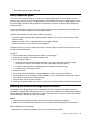
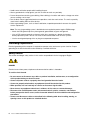
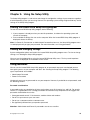
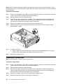
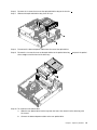
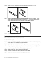
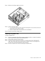
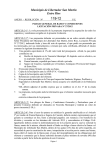
1
Lenovo H520s
Hardware Maintenance Manual
ideaideaideaCentreidea
Machine Types: 10093/2561/4746
Lenovo H520s
Hardware Maintenance Manual
Machine Types: 10093/2561/4746
Contents
Chapter 1. About this manual . . . . . . 1
Important Safety Information . . . . . . . . . .
1
Chapter 2. Safety information . . . . . . 3
General safety . . . . . . . . . . . .
Electrical safety . . . . . . . . . . .
Safety inspection guide . . . . . . . .
Handling electrostatic discharge-sensitive
devices . . . . . . . . . . . . . .
Grounding requirements . . . . . . . .
Safety notices . . . . . . . . . . . .
. . . .
. . . .
. . . .
3
3
5
. . . .
. . . .
. . . .
5
6
6
Chapter 3. General information . . . . . 9
Specifications . . . . . . . . . . . . . . . .
9
Chapter 4. General Checkout . . . . .
11
Chapter 5. Using the Setup Utility. . .
13
Starting the Lenovo BIOS Setup Utility program
Viewing and changing settings . . . . . . .
Using passwords. . . . . . . . . . . . .
Enabling or disabling a device . . . . . . .
Selecting a startup device . . . . . . . . .
Exiting the Lenovo BIOS Setup Utility program .
.
.
.
.
.
.
13
13
13
15
16
17
Chapter 6. Symptom-to-FRU Index . .
19
Hard disk drive boot error . . . . . . . . . .
Power Supply Problems . . . . . . . . . . .
POST error codes . . . . . . . . . . . . .
19
19
20
© Copyright Lenovo 2012
Undetermined problems . . . . . . . . . . .
20
Chapter 7. Locating connectors,
controls and components . . . . . .
21
Chapter 8. Replacing hardware . . . .
27
General information . . . . . . . . . .
Replacing the keyboard and mouse . . .
Removing the computer cover . . . . .
Removing the front bezel . . . . . . .
Replacing an optical drive . . . . . . .
Replacing the hard disk drive . . . . . .
Replacing a memory module . . . . . .
Replacing the Power supply . . . . . .
Replacing the graphic card . . . . . . .
Replacing the system fan . . . . . . .
Replacing the microprocessor fan . . . .
Replacing the heat-sink . . . . . . . .
Replacing the CPU . . . . . . . . . .
Replacing the Wi-Fi card. . . . . . . .
Replacing the front USB/card reader/audio
module . . . . . . . . . . . . . .
Replacing the motherboard. . . . . . .
FRU lists . . . . . . . . . . . . . .
.
.
.
.
.
.
.
.
.
.
.
.
.
.
27
28
28
29
30
32
33
34
35
37
37
38
39
41
. . .
. . .
. . .
42
43
45
Chapter 9. General information . . . .
53
Additional Service Information
.
.
.
.
.
.
.
.
.
.
.
.
.
.
.
.
.
.
.
.
.
.
.
.
.
.
.
.
. . . . . . . .
53
iii
iv
Lenovo H520sHardware Maintenance Manual
Chapter 1. About this manual
This manual contains service and reference information for Lenovo H520s computers listed on the cover. It
is intended only for trained servicers who are familiar with Lenovo computer products.
Before servicing a Lenovo product, be sure to read the Safety Information.
The description of the TV card in this manual is only used for the machines which have the TV card. It is
invalid for those machines which do not have TV card.
Important Safety Information
Be sure to read all caution and danger statements in this book before performing any of the instructions.
Veuillez lire toutes les consignes de type DANGER et ATTENTION du présent document avant d’exécuter
les instructions.
Lesen Sie unbedingt alle Hinweise vom Typ “ACHTUNG” oder “VORSICHT” in dieser Dokumentation, bevor
Sie irgendwelche Vorgänge durchführen
Leggere le istruzioni introdotte da ATTENZIONE e PERICOLO presenti nel manuale prima di eseguire una
qualsiasi delle istruzioni
Certifique-se de ler todas as instruções de cuidado e perigo neste manual antes de executar qualquer
uma das instruções
Es importante que lea todas las declaraciones de precaución y de peligro de este manual antes de seguir
las instrucciones.
© Copyright Lenovo 2012
1
2
Lenovo H520sHardware Maintenance Manual
Chapter 2. Safety information
This chapter contains the safety information that you need to be familiar with before servicing a computer.
General safety
Follow these rules to ensure general safety:
• Observe good housekeeping in the area of the machines during and after maintenance.
• When lifting any heavy object:
1. Ensure you can stand safely without slipping.
2. Distribute the weight of the object equally between your feet.
3. Use a slow lifting force. Never move suddenly or twist when you attempt to lift.
4. Lift by standing or by pushing up with your leg muscles; this action removes the strain from the
muscles in your back.
Do not attempt to lift any objects that weigh more than 16 kg (35 lb) or objects that you think are
too heavy for you.
• Do not perform any action that causes hazards to the customer, or that makes the equipment unsafe.
• Before you start the machine, ensure that other service representatives and the customer’s personnel are
not in a hazardous position.
• Place removed covers and other parts in a safe place, away from all personnel, while you are servicing
the machine.
• Keep your tool case away from walk areas so that other people will not trip over it.
• Do not wear loose clothing that can be trapped in the moving parts of a machine. Ensure that your sleeves
are fastened or rolled up above your elbows. If your hair is long, fasten it.
• Insert the ends of your necktie or scarf inside clothing or fasten it with a nonconductive clip, approximately
8 centimeters (3 inches) from the end.
• Do not wear jewelry, chains, metal-frame eyeglasses, or metal fasteners for your clothing.
Remember: Metal objects are good electrical conductors.
• Wear safety glasses when you are: hammering, drilling soldering, cutting wire, attaching springs, using
solvents, or working in any other conditions that might be hazardous to your eyes.
• After service, reinstall all safety shields, guards, labels, and ground wires. Replace any safety device
that is worn or defective.
• Reinstall all covers correctly before returning the machine to the customer.
Electrical safety
CAUTION:
Electrical current from power, telephone, and communication cables can be hazardous. To avoid
personal injury or equipment damage, disconnect the attached power cords, telecommunication
systems, networks, and modems before you open the computer covers, unless instructed otherwise
in the installation and configuration procedures.
© Copyright Lenovo 2012
3
Observe the following rules when working on electrical equipment.
Important: Use only approved tools and test equipment. Some hand tools have handles covered with a soft
material that does not insulate you when working with live electrical currents. Many customers have, near
their equipment, rubber floor mats that contain small conductive fibers to decrease electrostatic discharges.
Do not use this type of mat to protect yourself from electrical shock.
• Find the room emergency power-off (EPO) switch, disconnecting switch, or electrical outlet. If an electrical
accident occurs, you can then operate the switch or unplug the power cord quickly.
• Do not work alone under hazardous conditions or near equipment that has hazardous voltages.
• Disconnect all power before:
– Performing a mechanical inspection
– Working near power supplies
– Removing or installing Field Replaceable Units (FRUs)
• Before you start to work on the machine, unplug the power cord. If you cannot unplug it, ask the customer
to power-off the wall box that supplies power to the machine and to lock the wall box in the off position.
• If you need to work on a machine that has exposed electrical circuits, observe the following precautions:
– Ensure that another person, familiar with the power-off controls, is near you.
Remember: Another person must be there to switch off the power, if necessary.
– Use only one hand when working with powered-on electrical equipment; keep the other hand in your
pocket or behind your back.
Remember: There must be a complete circuit to cause electrical shock. By observing the above rule,
you may prevent a current from passing through your body.
– When using a tester, set the controls correctly and use the approved probe leads and accessories for
that tester.
– Stand on suitable rubber mats (obtained locally, if necessary) to insulate you from grounds such as
metal floor strips and machine frames.
Observe the special safety precautions when you work with very high voltages; these instructions are in
the safety sections of maintenance information. Use extreme care when measuring high voltages.
• Regularly inspect and maintain your electrical hand tools for safe operational condition.
• Do not use worn or broken tools and testers.
• Never assume that power has been disconnected from a circuit. First, check that it has been powered-off.
• Always look carefully for possible hazards in your work area. Examples of these hazards are moist floors,
nongrounded power extension cables, power surges, and missing safety grounds.
• Do not touch live electrical circuits with the reflective surface of a plastic dental mirror. The surface is
conductive; such touching can cause personal injury and machine damage.
• Do not service the following parts with the power on when they are removed from their normal operating
places in a machine:
– Power supply units
– Pumps
– Blowers and fans
– Motor generators
and similar units. (This practice ensures correct grounding of the units.)
• If an electrical accident occurs:
– Use caution; do not become a victim yourself.
– Switch off power.
4
Lenovo H520sHardware Maintenance Manual
– Send another person to get medical aid.
Safety inspection guide
The intent of this inspection guide is to assist you in identifying potentially unsafe conditions on these
products. Each machine, as it was designed and built, had required safety items installed to protect users
and service personnel from injury. This guide addresses only those items. However, good judgment should
be used to identify potential safety hazards due to attachment of features or options not covered by this
inspection guide.
If any unsafe conditions are present, you must determine how serious the apparent hazard could be and
whether you can continue without first correcting the problem.
Consider these conditions and the safety hazards they present:
• Electrical hazards, especially primary power (primary voltage on the frame can cause serious or fatal
electrical shock).
• Explosive hazards, such as a damaged CRT face or bulging capacitor
• Mechanical hazards, such as loose or missing hardware
The guide consists of a series of steps presented in a checklist. Begin the checks with the power off, and
the power cord disconnected.
Checklist:
1. Check exterior covers for damage (loose, broken, or sharp edges).
2. Power-off the computer. Disconnect the power cord.
3. Check the power cord for:
a. A third-wire ground connector in good condition. Use a meter to measure third-wire ground
continuity for 0.1 ohm or less between the external ground pin and frame ground.
b. The power cord should be the appropriate type as specified in the parts listings.
c. Insulation must not be frayed or worn.
4. Remove the cover.
5. Check for any obvious alterations. Use good judgment as to the safety of any alterations.
6. Check inside the unit for any obvious unsafe conditions, such as metal filings, contamination, water or
other liquids, or signs of fire or smoke damage.
7. Check for worn, frayed, or pinched cables.
8. Check that the power-supply cover fasteners (screws or rivets) have not been removed or tampered with.
Handling electrostatic discharge-sensitive devices
Any computer part containing transistors or integrated circuits (ICs) should be considered sensitive to
electrostatic discharge (ESD). ESD damage can occur when there is a difference in charge between objects.
Protect against ESD damage by equalizing the charge so that the machine, the part, the work mat, and the
person handling the part are all at the same charge.
Notes:
1. Use product-specific ESD procedures when they exceed the requirements noted here.
2. Make sure that the ESD protective devices you use have been certified (ISO 9000) as fully effective.
When handling ESD-sensitive parts:
• Keep the parts in protective packages until they are inserted into the product.
Chapter 2. Safety information
5
• Avoid contact with other people while handling the part.
• Wear a grounded wrist strap against your skin to eliminate static on your body.
• Prevent the part from touching your clothing. Most clothing is insulative and retains a charge even when
you are wearing a wrist strap.
• Use the black side of a grounded work mat to provide a static-free work surface. The mat is especially
useful when handling ESD-sensitive devices.
• Select a grounding system, such as those listed below, to provide protection that meets the specific
service requirement.
Note: The use of a grounding system is desirable but not required to protect against ESD damage.
– Attach the ESD ground clip to any frame ground, ground braid, or green-wire ground.
– Use an ESD common ground or reference point when working on a double-insulated or
battery-operated system. You can use coax or connector-outside shells on these systems.
– Use the round ground-prong of the ac plug on ac-operated computers.
Grounding requirements
Electrical grounding of the computer is required for operator safety and correct system function. Proper
grounding of the electrical outlet can be verified by a certified electrician.
Safety notices
The caution and danger safety notices in this section are provided in the the language of English.
DANGER
Electrical current from power, telephone and communication cables is hazardous.
To avoid a shock hazard:
• Do not connect or disconnect any cables or perform installation, maintenance, or reconfiguration
of this product during an electrical storm.
• Connect all power cords to a properly wired and grounded electrical outlet.
• Connect to properly wired outlets any equipment that will be attached to this product.
• When possible, use one hand only to connect or disconnect signal cables.
• Never turn on any equipment when there is evidence of fire, water, or structural damage.
• Disconnect the attached power cords, telecommunications systems, networks, and modems
before you open the device covers, unless instructed otherwise in the installation and configuration
procedures.
• Connect and disconnect cables as described in the following table when installing, moving, or
opening covers on this product or attached devices.
6
Lenovo H520sHardware Maintenance Manual
To Connect
To Disconnect
1. Turn everything OFF.
1. Turn everything OFF.
2. First, attach all cables to devices.
2. First, remove power cords from outlet.
3. Attach signal cables to connectors.
3. Remove signal cables from connectors.
4. Attach power cords to outlet.
4. Remove all cables from devices.
5. Turn device ON.
CAUTION:
When replacing the lithium battery, use only Part Number 45C1566 or an equivalent type battery
recommended by the manufacturer. If your system has a module containing a lithium battery, replace
it only with the same module type made by the same manufacturer. The battery contains lithium and
can explode if not properly used, handled, or disposed of.
Do not:
• Throw or immerse into water
• Heat to more than 100°C (212°F)
• Repair or disassemble
Dispose of the battery as required by local ordinances or regulations.
CAUTION:
When laser products (such as CD-ROMs, DVD-ROM drives, fiber optic devices, or transmitters) are
installed, note the following:
• Do not remove the covers. Removing the covers of the laser product could result in exposure to
hazardous laser radiation. There are no serviceable parts inside the device.
• Use of controls or adjustments or performance of procedures other than those specified herein
might result in hazardous radiation exposure.
DANGER
Some laser products contain an embedded Class 3A or Class 3B laser diode. Note the following:
Laser radiation when open. Do not stare into the beam, do not view directly with optical
instruments, and avoid direct exposure to the beam.
Chapter 2. Safety information
7
≥18 kg(37 lbs)
≥32 kg(70.5 lbs)
≥55 kg(121.2 lbs)
CAUTION:
Use safe practices when lifting.
CAUTION:
The power control button on the device and the power switch on the power supply do not turn off
the electrical current supplied to the device. The device also might have more than one power
cord. To remove all electrical current from the device, ensure that all power cords are disconnected
from the power source.
2
1
CAUTION:
Do not place any object weighing more than 82 kg (180 lbs.) on top of rack-mounted devices.
8
Lenovo H520sHardware Maintenance Manual
Chapter 3. General information
This chapter provides general information that applies to all machine types supported by this publication.
Specifications
This section lists the physical specifications for your computer.
This section lists the physical specifications for your computer.
Type Lenovo H520s
This section lists the physical specifications.
Environment
Air temperature:
Operating: 10° to 35°C
Transit: -20° to 55°C
Humidity:
Operating: 35% to 80%
Transit: 20% to 90% (40°C)
Altitude: 86KPa to 106KPa
Electrical input:
Input voltage: 90V-264V(AC)
Input frequency: 47Hz-63Hz
© Copyright Lenovo 2012
9
10
Lenovo H520sHardware Maintenance Manual
Chapter 4. General Checkout
Attention: The drives in the computer you are servicing might have been rearranged or the drive startup
sequence changed. Be extremely careful during write operations such as copying, saving, or formatting.
Data or programs can be overwritten if you select an incorrect drive.
General error messages appear if a problem or conflict is found by an application program, the operating
system, or both. For an explanation of these messages, refer to the information supplied with that software
package.
Use the following procedure to help determine the cause of the problem:
1. Power-off the computer and all external devices.
2. Check all cables and power cords.
3. Set all display controls to the middle position.
4. Power-on all external devices.
5. Power-on the computer.
• Look for displayed error codes
• Look for readable instructions or a main menu on the display.
If you did not receive the correct response, proceed to step 6.
If you do receive the correct response, proceed to step 7.
6. Look at the following conditions and follow the instructions:
• If the computer displays a POST error, go to “POST error codes”.
• If the computer hangs and no error is displayed, continue at step 7.
7. If the test stops and you cannot continue, replace the last device tested.
© Copyright Lenovo 2012
11
12
Lenovo H520sHardware Maintenance Manual
Chapter 5. Using the Setup Utility
The Setup Utility program is used to view and change the configuration settings of your computer, regardless
of which operating system you are using. However, the operating-system settings might override any similar
settings in the Setup Utility program.
Starting the Lenovo BIOS Setup Utility program
To start the Lenovo BIOS Setup Utility program, do the following:
1. If your computer is already on when you start this procedure, shut down the operating system and
turn off the computer.
2. Press and hold the F1 key then turn on the computer. When the Lenovo BIOS Setup Utility program is
displayed, release the F1 key.
Note: If a Power-On Password or an Administrator Password has been set, the Setup Utility program menu
is not displayed until you type your password. For more information, see “Using passwords.”
Viewing and changing settings
System configuration options are listed in the Lenovo BIOS Setup Utility program menu. To view or change
settings, see “Starting the Setup Utility program.”
You must use the keyboard when using the Lenovo BIOS Setup Utility menu. The keys used to perform
various tasks are displayed on the bottom of each screen.
Using passwords
You can use the Lenovo BIOS Setup Utility program to set passwords to prevent unauthorized persons
from gaining access to your computer and data. See “Starting the Setup Utility program.” The following
types of passwords are available:
• Administrator Password
• Power-On Password
You do not have to set any passwords to use your computer. However, if you decide to set passwords, read
the following sections.
Password considerations
A password can be any combination of letters and numbers up to 16 character (a-z, and 0-9). For security
reasons, it is a good idea to use a strong password that cannot be easily compromised. We suggest that
passwords should follow these rules:
• Strong passwords contain 7-16 characters, combine letters and numbers.
• Do not use your name or your user name.
• Do not use a common word or a common name.
• Be significantly different from your previous password.
Attention: Administrator and Power-On passwords are not case sensitive
© Copyright Lenovo 2012
13
Administrator Password
Setting an Administrator Password deters unauthorized persons from changing configuration settings. You
might want to set an Administrator Password if you are responsible for maintaining the settings of several
computers.
After you set an Administrator Password, a password prompt is displayed every time you access the Lenovo
BIOS Setup Utility program.
If both the Administrator and Power-On Password are set, you can type either password. However, you must
use your Administrator Password to change any configuration settings.
Setting, changing, or deleting an Administrator password
To set an Administrator Password, do the following:
Note: A password can be any combination of letters and numbers up to 16 character (a-z, and 0-9). For
more information, see “Password considerations” on page 13.
1. Start the Lenovo BIOS Setup Utility program (see “Starting the Lenovo BIOS Setup Utility program” on
page 13).
2. From the Security menu, select Set Administrator Password and press the Enter key.
3. The password dialog box will be displayed. Type the password then press the Enter key.
4. Re-type the password to confirm, then press the Enter key. If you type the password correctly, the
password will be installed.
To change an Administrator Password, do the following:
1. Start the Lenovo BIOS Setup Utility program (see “Starting the Lenovo BIOS Setup Utility program” on
page 13).
2. From the Security menu, select Set Administrator Password and press the Enter key.
3. The password dialog box will be displayed. Type the current password then press Enter key.
4. Type the new password, then press Enter key. Re-type the password to confirm the new password, if
you type the new password correctly, the new password will be installed. A Setup Notice will display
that changes have been saved.
To delete a previously set Administrator Password, do the following :
1. From the Security menu, select Set Administrator Password and press the Enter key.
2. The password dialog box will be displayed. Type the current password and press the Enter key.
3. To delete an Administrator Password, Enter blank fields for each new password line item. A setup
notice will display that changes have been saved.
4. Return to the Lenovo BIOS Setup Utility program menu and select the Exit option.
5. Select Save changes and Exit from the menu.
Power-On Password
When a Power-On Password is set, you cannot start the Lenovo BIOS Setup Utility program until a valid
password is typed from the keyboard.
Setting, changing, or deleting a Power-On Password
Note: A password can be any combination of letters and numbers up to 16 character (a-z, and 0-9).
14
Lenovo H520sHardware Maintenance Manual
To set a Power-On Password, do the following:
1. Start the Lenovo BIOS Setup Utility program (See ”Starting the Lenovo BIOS Setup Utility program” on
page 13.)
2. From the Security menu, select Set Power-On Password and press the Enter key.
3. The password dialog box will be displayed. Type the password, and press the Enter key.
4. Re-type the password to confirm, if you type the password correctly, the password will be installed.
To change a Power-On Password, do the following:
1. Start the Lenovo BIOS Setup Utility program (See ”Starting the Lenovo BIOS Setup Utility program” on
page 13.)
2. From the Security menu, select Set Power-On Password and press the Enter key.
3. The password dialog box will be displayed. Type the current password then press the Enter key.
4. Type the new password, then press the Enter key. Re-type the password to confirm the new password,
if you type the new password correctly, the new password will be installed. A setup notice will display
that changes have been saved.
To delete a previously set Power-On Password, do the following :
1. From the Security menu, select Set Power-On Password and press the Enter key.
2. The password dialog box will be displayed. Type the current password and press the Enter key.
3. To delete the Power-On Password, Enter blank fields for each new password line item. A setup
notice will display that changes have been saved.
4. Return to the Lenovo BIOS Setup Utility program menu and select the Exit option.
5. Select Save changes and Exit from the menu.
Enabling or disabling a device
The Devices options is used to enable or disable user access to the following devices:
Serial Port Setup
Select this option to enable or disable Serial Port (com).
USB Functions
Select whether to enable or disable USB (Universal Serial
Bus) functions. If it is disabled, the USB keyboard and/or
USB mouse may be not able to be used without device
driver support.
ATA Drive Setup
Select IDE, ACHI mode or disable SATA controller. Device
driver support is required for ACHI mode. Depending on
how the hard disk image was installed, changing this
setting may prevent the system from booting.
Video Setup
To configure video related functions. This option allows
you to configure system's initiate graphic adapter from
either IGD (Integrated Graphics Device) or PEG (PCI
Express Graphics). Keep on the IGD enabled based on
the setup options.
Chapter 5. Using the Setup Utility
15
Onboard Audio Controller
Select whether to enable or disable the Onboard Audio
Controller, when feature is set to Disabled all devices
connected to the audio connectors (e.g. a headphone or
a microphone) are disabled and can’t be used.
Onboard Ethernet Controller or LAN Boot Agent
Select whether to enable or disable Onboard Ethernet
Controller, or select whether to enable or disable load
onboard PXE (Preboot Execution Environment), or
SMC (Secure Managed Client). This feature will allow
the computer to boot from a server image.
To enable or disable a device, do the following:
1. Start the Setup Utility program (see “Starting the Setup Utility program” on page 13).
2. From the Setup Utility program menu, select Devices.
3. Select:
Serial Port Setup press the Enter key, and then select Serial Port Setup.
USB Setup press the Enter key, and then select USB Functions.
ATA Device Setup press the Enter key. Select Configure SATA as, press the Enter key and then
select SATA mode.
Video Setup press the Enter key, and then select Video Setup.
Audio Setup press the Enter key, and then select Onboard Audio Controller.
Network Setup press the Enter key, then select Onboard Ethernet Support or LAN Boot Agent.
4. Select Disabled or Enabled and press the Enter key.
5. Return to the Lenovo BIOS Setup Utility program menu and select the Exit option.
6. Select Save changes and Exit from the menu.
Note: If you do not want to save the settings, select Discard changes and Exit from the menu.
Selecting a startup device
If your computer does not boot from a device such as the CD/DVD-ROM drive disk or hard disk as expected,
follow one of the procedures below.
Selecting a temporary startup device
Use this procedure to startup from any boot device.
Note: Not all CDs, DVDs or hard disk drives are bootable.
1. Turn off your computer.
2. Press and hold the F12 key then turn on the computer. When the Startup Device Menu appears,
release the F12 key.
Note: If the Startup Device Menu does not display using these steps, repeatedly press and release the
F12 key rather than keeping it pressed when turning on the computer.
3. Use ↑ and ↓ arrows to select the desired startup device from the Startup Device Menu and press
the Enter key to begin.
Note: Selecting a startup device from the Startup Device Menu does not permanently change the
startup sequence.
Selecting or changing the startup device sequence
16
Lenovo H520sHardware Maintenance Manual
To view or permanently change the configured startup device sequence, do the following:
1. Start the Lenovo BIOS Setup Utility program (see “Starting the Lenovo BIOS Setup Utility program” on
page 13).
2. From the Lenovo BIOS Setup Utility program main menu, select the Startup option.
3. Press the Enter key, and select the devices for the Primary Boot Sequence. Read the information
displayed on the right side of the screen.
4. Use - and ¯ arrows to select a device. Use the <+> or <-> keys to move a device up or down. Use the
<×> key to exclude the device from or include the device in the boot sequence.
5. Return to the Lenovo BIOS Setup Utility program menu and select the Exit option.
6. Select Save changes and Exit from the menu.
Notes:
a. If you do not want to save the settings, select Discard changes and Exit from the menu.
b. If you have changed these settings and want to return to the default settings, select Load Optimal
Defaults from the menu.
Exiting the Lenovo BIOS Setup Utility program
After you finish viewing or changing settings, press the Esc key to return to the Lenovo BIOS Setup Utility
program main menu. You might have to press the Esc key several times. Do one of the following:
• If you want to save the new settings, select Save changes and Exit from the menu. When the Save &
reset window shows, select the Yes button, and then press the Enter key to exit the Lenovo BIOS
Setup Utility program.
• If you do not want to save the settings, select Discard changes and Exit from the menu. When the
Reset Without Saving window shows, select the Yes button, and then press the Enter key to exit the
Setup Utility program.
Chapter 5. Using the Setup Utility
17
18
Lenovo H520sHardware Maintenance Manual
Chapter 6. Symptom-to-FRU Index
The Symptom-to-FRU index lists error symptoms and possible causes. The most likely cause is listed first.
Always begin with Chapter 4, “General Checkout,” on page 11. This index can also be used to help you
decide which FRUs to have available when servicing a computer. If you are unable to correct the problem
using this index, go to “Undetermined problems” on page 20.
Notes:
• If you have both an error message and an incorrect audio response, diagnose the error message first.
• If you cannot run the diagnostic tests or you get a diagnostic error code when running a test but did
receive a POST error message, diagnose the POST error message first.
• If you did not receive any error message look for a description of your error symptoms in the first part of
this index.
Hard disk drive boot error
A hard disk drive boot error can have the following causes.
Error
FRU/Action
The startup drive is not included in the boot sequence
in configuration.
Check the configuration and ensure the startup drive is
in the boot sequence.
No operating system installed on the boot drive.
Install an operating system on the boot drive.
The boot sector on the startup drive is corrupted.
The drive must be formatted. Do the following:
1. Attempt to back-up the data on the failing hard disk
drive.
2. Use the operating system to format the hard disk
drive.
The drive is defective.
Replace the hard disk drive.
Power Supply Problems
Follow these procedures if you suspect there is a power supply problem.
Check/Verify
FRU/Action
Check that the following are properly installed:
Reseat connectors
• Power Cord
•
On/Off Switch connector
• System Board Power Supply connectors
• Microprocessor(s) connection
Check the power cord.
Power Cord
Check the power-on switch.
Power-on Switch
© Copyright Lenovo 2012
19
POST error codes
Each time you turn the computer on, it performs a series of tests to check that the system is operating
correctly and that certain options are set. This series of tests is called the Power-On Self-Test, or POST.
POST does the following:
• Checks some basic system-board operations
• Checks that the memory is working correctly
• Starts video operations
• Verifies that the boot drive is working
POST Error Message
Description/Action
Keyboard error
Cannot initialize the keyboard. Make sure the keyboard
is properly connected to the computer and that no keys
are held pressed during POST. To purposely configure
the computer without a keyboard, select Keyboardless
operation in Startup option to Enabled. The BIOS then
ignores the missing keyboard during POST.
Reboot and Select proper Boot device or Insert Boot
Media in selected Boot device
The BIOS was unable to find a suitable boot device. Make
sure the boot drive is properly connected to the computer.
Make sure you have bootable media in the boot device.
Undetermined problems
1. Power-off the computer.
2. Remove or disconnect the following components (if connected or installed) one at a time.
a. External devices (modem, printer, or mouse)
b. Extended video memory
c. External Cache
d. External Cache RAM
e. Hard disk drive
f. Disk drive
3. Power-on the computer to re-test the system.
4. Repeat steps 1 through 3 until you find the failing device or component.
If all devices and components have been removed and the problem continues, replace the system board.
20
Lenovo H520sHardware Maintenance Manual
Chapter 7. Locating connectors, controls and components
This section provides illustrations to help locate the various connectors, controls and components of the
computer.
© Copyright Lenovo 2012
21
Font view
The following illustration shows the location of controls and components on the front of the computer.
Attention: Be careful not to block any air vents on the computer. Blocked air vents can cause overheating.
1. Power button
5. Headphone connector
2. Memory card reader (selected models only)
6. Optical Drive (selected models only)
3. USB connectors
7. Hard disk drive indicator
4. Optical drive eject button
8. Microphone connector
Attention: The effective range of the Built-in IR Emitter is 10 feet (3m).
22
Lenovo H520sHardware Maintenance Manual
Rear view
The following illustration shows the location of connectors and components on the rear of the computer.
1. USB connectors
6. Audio connectors
2. WiFi antenna (selected models only)
7. PCI Express X 16 graphics adapter connector (some
models are equipped with a graphics card)
3. HDMI connector (selected models only)
8. PCI Express X 1 adapter connector (some models are
equipped with USB 3.0 or TV tuner card)
4. On-board VGA connector
9. Power connector
5. Ethernet connector
10. Voltage selection switch (selected models only)
Chapter 7. Locating connectors, controls and components
23
Hardware components
The following illustration shows the components that make up your computer.
3
2
1
4
5
1. Heatsink and microprocessor fan
4. Hard disk drive
2. System board
5. Power supply
3. Optical disk drive and bay
24
Lenovo H520sHardware Maintenance Manual
Identifying parts on the motherboard
The motherboard (sometimes called the planar or system board) is the main circuit board in your computer.
It provides basic computing functions and supports a variety of devices that are factory-installed or that
you can install later. The following illustration shows the location of connectors and components on the
front of the motherboard.
1
2
3
4
5
6
7
8
9
18 17 16
15
14
13
12
11 10
1. 12V power connector
11. Front panel connector
2. Microprocessor and heat sink
12. Clear CMOS jumper
3. Microprocessor fan header
13. Front USB connectors (2)
4. Memory slots (2)
14. Mini PCI-E slot
5. Thermal sensor header
15. Mode switch connector
6. Power connector
16. Serial (COM2) connector
7. Battery
17. PCI express X 1 adapter slots (3)
8. SATA connectors (3)
18. Front audio connector
9. eSATA connector
19. PCI express X 16 adapter slot
10. Power fan header
20. System fan header
Chapter 7. Locating connectors, controls and components
25
26
Lenovo H520sHardware Maintenance Manual
Chapter 8. Replacing hardware
Attention: Do not remove the computer cover or attempt any repair before reading the “Important safety information”
in the Safety and Warranty Guide that was included with your computer. To obtain copies of the Safety and Warranty
Guide, go to the Support Web site at: http://consumersupport.lenovo.com.
Note: Use only parts provided by Lenovo.
General information
Pre-disassembly instructions
Before proceeding with the disassembly procedure, make sure that you do the following:
1. Turn off the power to the system and all peripherals.
2. Unplug all power and signal cables from the computer.
3. Place the system on a flat, stable surface.
© Copyright Lenovo 2012
27
Replacing the keyboard and mouse
To replace the keyboard and mouse
Step 1.
Remove any media (disks, CDs, DVDs or memory cards) from the drives, shut down the operating
system, and turn off the computer and all attached devices.
Step 2.
Unplug all power cords from electrical outlets.
Step 3.
Disconnect all cables attached to the computer. This includes power cords, input/output (I/O)
cables, and any other cables that are connected to the computer. Refer to “Left and right view”
and “Rear view” for help with locating the various connectors.
Note: Your keyboard will be connected to a USB connector on one side or at the rear of the
computer.
Step 4.
Disconnect the defective keyboard cable from the computer and connect the new keyboard cable
to the same connector.
Note: The mouse can be replaced using the same method.
Removing the computer cover
Attention: Turn off the computer and wait 3 to 5 minutes to let it cool down before removing the cover.
Note: It may be helpful to place the computer face-down on a soft flat surface for this procedure. Lenovo
recommends that you use a blanket, towel, or other soft cloth to protect the computer screen from scratches
or other damage.
To remove the computer cover:
Step 1.
Remove any media (disks, CDs, DVDs, or memory cards) from the drives, shut down the operating
system, and turn off the computer and all attached devices.
Step 2.
Unplug all power cords from electrical outlets.
Step 3.
Disconnect all cables attached to the computer. This includes power cords, input/output (I/O)
cables, and any other cables that are connected to the computer. Refer to “Left and right view”
and “Rear view” for help with locating the various connectors.
28
Lenovo H520sHardware Maintenance Manual
Step 4.
Remove the 2 screws that secure the computer cover at the rear of the chassis.
Step 5.
To reinstall the computer cover:
a.
Line up the computer cover with the chassis then slide it back.
b.
Secure the computer cover to the chassis with the screws.
Removing the front bezel
Attention: Turn off the computer and wait 3 to 5 minutes to let it cool down before removing the cover.
Chapter 8. Replacing hardware
29
Note: It may be helpful to place the computer face-down on a soft flat surface for this procedure. Lenovo
recommends that you use a blanket, towel, or other soft cloth to protect the computer screen from scratches
or other damage.
To remove the front bezel:
Step 1.
Remove any media (disks, CDs, DVDs, or memory cards) from the drives, shut down the operating
system, and turn off the computer and all attached devices.
Step 2.
Unplug all power cords from electrical outlets.
Step 3.
Disconnect all cables attached to the computer. This includes power cords, input/output (I/O)
cables, and any other cables that are connected to the computer. Refer to “Left and right view”
and “Rear view” for help with locating the various connectors.
Step 4.
Remove the computer cover. Refer to “Removing the computer cover”.
Step 5.
Remove the front bezel by releasing the three plastic tabs inside the chassis and pushing the
bezel outward as shown.
Step 6.
To reattach the bezel:
a.
Step 7.
Align the plastic tabs on the bottom of the bezel with the corresponding holes in the chassis,
and then snap it into position at the bottom and top of the chassis.
Reattach the computer cover.
Replacing an optical drive
Note: For this procedure, it helps to lay the computer flat.
To replace an optical drive:
Step 1.
Remove any media (disks, CDs, DVDs, or memory cards) from the drives, shut down the operating
system, and turn off the computer and all attached devices.
Step 2.
Unplug all power cords from electrical outlets.
Step 3.
Disconnect all cables attached to the computer. This includes power cords, input/output (I/O)
cables, and any other cables that are connected to the computer. Refer to “Left and right view”
and “Rear view” for help with locating the various connectors.
Step 4.
Remove the computer cover. Refer to “Removing the computer cover”.
Step 5.
Remove the front bezel. Refer to “Removing the front bezel”.
30
Lenovo H520sHardware Maintenance Manual
Step 6.
Remove the 2 screws that secure the optical disk drive bay to the chassis. 1
Step 7.
Slide out the optical disk drive bay, then lift it up. 2
2
1
Step 8.
Disconnect the data and power cables from the rear of the optical drive. 3
Step 9.
Remove the 2 screws that secure the optical drive to the optical drive bay 4 and push the optical
drive straight out of the front of the drive bay. 5
5
3
4
Step 10. To install the new optical drive:
a.
Slide the new optical drive into the bay from the front, then attach it to the drive bay with
the screws.
b.
Connect the data and power cables to the new optical drive.
Chapter 8. Replacing hardware
31
c.
Slide the optical disk drive bay back, then push it in and reattach it to the chassis with the
screws.
Step 11. Reattach the front bezel, computer cover.
Replacing the hard disk drive
Note: For this procedure, it helps to lay the computer flat.
To replace the hard disk drive:
Step 1.
Remove any media (disks, CDs, DVDs, or memory cards) from the drives, shut down the operating
system, and turn off the computer and all attached devices.
Step 2.
Unplug all power cords from electrical outlets.
Step 3.
Disconnect all cables attached to the computer. This includes power cords, input/output (I/O)
cables, and any other cables that are connected to the computer. Refer to “Left and right view”
and “Rear view” for help with locating the various connectors.
Step 4.
Remove the computer cover. Refer to “Removing the computer cover”.
Step 5.
Remove the front bezel. Refer to “Removing the front bezel”.
Step 6.
Remove the optical disk drive bay. Refer to “Replacing an optical drive”.
Step 7.
Remove the screw that secures the hard disk drive bay to the chassis.
Step 8.
Slide out the hard disk drive bay, then lift it up. Disconnect the data and power cables from
the hard disk drive.
4
2
3
1
Step 9.
32
Remove the 4 screws that secure the hard disk drive to the bay.
Lenovo H520sHardware Maintenance Manual
Step 10. Slide the hard disk drive out of the bay.
Step 11. Install the new hard disk drive:
a.
Insert the new hard disk drive into the drive bay.
b.
Screw back the 4 screws on the drive bay.
c.
Attach the data and power cables to the new hard disk drive.
d.
Line up the hard disk drive bay, then slide it in. Reattach it to the chassis with the screws.
Step 12. Reattach the optical drive, front bezel and computer cover.
Replacing a memory module
Note: For this procedure, it helps to lay the computer flat.
To replace an optical drive:
Step 1.
Remove any media (disks, CDs, DVDs, or memory cards) from the drives, shut down the operating
system, and turn off the computer and all attached devices.
Step 2.
Unplug all power cords from electrical outlets.
Step 3.
Disconnect all cables attached to the computer. This includes power cords, input/output (I/O)
cables, and any other cables that are connected to the computer. Refer to “Left and right view”
and “Rear view” for help with locating the various connectors.
Step 4.
Remove the computer cover. Refer to “Removing the computer cover”.
Step 5.
Locate the memory module connectors. Refer to “Locating components”.
Chapter 8. Replacing hardware
33
Step 6.
Remove the memory module being replaced by opening the retaining clips as shown.
Step 7.
Position the new memory module over the memory connector. Make sure the notch 1 on the
memory module is correctly aligned with the connector key 2 on the system board. Push the
memory module straight down into the connector until the retaining clips close.
Step 8.
Reattach the computer cover.
Replacing the Power supply
Note: For this procedure, it helps to lay the computer flat.
To replace the Power supply:
Step 1.
Remove any media (disks, CDs, DVDs, or memory cards) from the drives, shut down the operating
system, and turn off the computer and all attached devices.
Step 2.
Unplug all power cords from electrical outlets.
Step 3.
Disconnect all cables attached to the computer. This includes power cords, input/output (I/O)
cables, and any other cables that are connected to the computer. Refer to “Left and right view”
and “Rear view” for help with locating the various connectors.
Step 4.
Remove the computer cover. Refer to “Removing the computer cover”.
Step 5.
Remove the front bezel. Refer to “Removing the front bezel”.
Step 6.
Disconnect the power cables from the connectors on motherboard.
Step 7.
Remove the 3 screws that secure the Power supply to the chassis.
34
Lenovo H520sHardware Maintenance Manual
Step 8.
Slide then lift the Power supply out of chassis.
Step 9.
Install the new power supply:
a.
Line up the holes on the new power supply with mounting holes on the rear of the chassis and
secure it to the chassis with the 3 screws.
b.
Connect the power cables to the connectors on the motherboard.
Step 10. Reattach the front bezel, computer cover.
Replacing the graphic card
To replace the graphic card:
Step 1.
Remove any media (disks, CDs, DVDs, or memory cards) from the drives, shut down the operating
system, and turn off the computer and all attached devices.
Step 2.
Unplug all power cords from electrical outlets.
Step 3.
Disconnect all cables attached to the computer. This includes power cords, input/output (I/O)
cables, and any other cables that are connected to the computer. Refer to “Left and right view”
and “Rear view” for help with locating the various connectors.
Step 4.
Remove the computer cover. Refer to “Removing the computer cover”.
Chapter 8. Replacing hardware
35
Step 5.
Remove the screw that secures the graphic card to the chassis, and slide out the metal bracket.
Step 6.
Push the pin that lock the graphic card, and pull it up then slide it out to remove it.
Step 7.
To install the new graphic card:
Step 8.
36
a.
Slide then insert the new graphic card to the same connector on the motherboard.
b.
Reattach the metal bracket back into position and secure the graphic card to the chassis
with the screw.
Reattach the computer cover.
Lenovo H520sHardware Maintenance Manual
Replacing the system fan
To replace the system fan:
Step 1.
Remove any media (disks, CDs, DVDs, or memory cards) from the drives, shut down the operating
system, and turn off the computer and all attached devices.
Step 2.
Unplug all power cords from electrical outlets.
Step 3.
Disconnect all cables attached to the computer. This includes power cords, input/output (I/O)
cables, and any other cables that are connected to the computer. Refer to “Left and right view”
and “Rear view” for help with locating the various connectors.
Step 4.
Remove the computer cover. Refer to “Removing the computer cover”.
Step 5.
Remove the front bezel. Refer to “Removing the front bezel”.
Step 6.
Disconnect the fan power cable from the connector on the motherboard.
Step 7.
Remove the 4 screws that secure the system fan to the heat-sink, slide then lift the system fan
out to remove it.
Step 8.
To install the new system fan:
Step 9.
a.
Line up the new system fan with the chassis and secure it to the chassis with 3 screws.
b.
Connect the system fan power cable to the connector on the board.
Reattach the front bezel, computer cover.
Replacing the microprocessor fan
To replace the microprocessor fan:
Step 1.
Remove any media (disks, CDs, DVDs, or memory cards) from the drives, shut down the operating
system, and turn off the computer and all attached devices.
Step 2.
Unplug all power cords from electrical outlets.
Step 3.
Disconnect all cables attached to the computer. This includes power cords, input/output (I/O)
cables, and any other cables that are connected to the computer. Refer to “Left and right view”
and “Rear view” for help with locating the various connectors.
Step 4.
Remove the computer cover. Refer to “Removing the computer cover”.
Step 5.
Disconnect the fan power cable from the connector on the motherboard.
Chapter 8. Replacing hardware
37
Step 6.
Remove the 4 screws that secure the microprocessor fan to the heat-sink and lift up the
microprocessor fan to remove it.
Step 7.
To install the new microprocessor fan:
Step 8.
a.
Line up the new microprocessor fan with the heat-sink and secure it to the heat-sink with
4 screws.
b.
Connect the microprocessor fan power cable to the connector on the board.
Reattach the computer cover.
Replacing the heat-sink
Note: For this procedure, it helps to lay the computer flat.
To replace the heat-sink:
Step 1.
Remove any media (disks, CDs, DVDs, or memory cards) from the drives, shut down the operating
system, and turn off the computer and all attached devices.
Step 2.
Unplug all power cords from electrical outlets.
38
Lenovo H520sHardware Maintenance Manual
Step 3.
Disconnect all cables attached to the computer. This includes power cords, input/output (I/O)
cables, and any other cables that are connected to the computer. Refer to “Left and right view”
and “Rear view” for help with locating the various connectors.
Step 4.
Remove the computer cover. Refer to “Removing the computer cover”.
Step 5.
Remove the microprocessor fan. Refer to “Replacing the microprocessor fan”.
Step 6.
Remove the 4 screws that secure the heat-sink to the motherboard.
Step 7.
Lift up the heat-sink to remove it.
Step 8.
Install the new heat-sink:
Step 9.
a.
Line up the screws on the new heat-sink with mounting holes on the motherboard and secure
it with the 4 screws.
b.
Reattach the microprocessor fan to the heat-sink.
c.
Reconnect the microprocessor fan power cable to the connector on the motherboard.
Reattach the computer cover.
Replacing the CPU
Note: For this procedure, it helps to lay the computer flat.
To replace the CPU:
Step 1.
Remove any media (disks, CDs, DVDs, or memory cards) from the drives, shut down the operating
system, and turn off the computer and all attached devices.
Step 2.
Unplug all power cords from electrical outlets.
Step 3.
Disconnect all cables attached to the computer. This includes power cords, input/output (I/O)
cables, and any other cables that are connected to the computer. Refer to “Left and right view”
and “Rear view” for help with locating the various connectors.
Step 4.
Remove the computer cover. Refer to “Removing the computer cover”.
Step 5.
Remove the microprocessor fan. Refer to “Replacing the microprocessor fan”.
Chapter 8. Replacing hardware
39
Step 6.
Remove the heat-sink. Refer to “Replacing the heat-sink”.
Step 7.
To remove the microprocessor 3 from the system board, press then slide the small handle out
to spring it up. 1 and open the retainer. 2
Attention: Do not touch the gold contacts on the bottom of the microprocessor. When handing the
microprocessor, touch only the sides.
Note: Do not drop anything onto the microprocessor socket while it is exposed. The socket pins must
be kept as clean as possible.
40
Lenovo H520sHardware Maintenance Manual
Step 8.
Holding the sides of the microprocessor with your fingers, remove the protective cover 1 that
protects the gold contacts on the new microprocessor. 2
Step 9.
Holding the sides of the microprocessor with your fingers, position the microprocessor so that the
notches on the microprocessor are aligned with the tabs in the microprocessor socket.
Important: To avoid damaging the microprocessor contacts, keep the microprocessor completely level
while installing it into the socket.
Step 10. Lower the microprocessor straight down into its socket on the motherboard.
Step 11. To secure the microprocessor in the socket, close the microprocessor retainer and lock it into
position with the small handle.
Step 12. Use a thermal grease syringe to place 5 drops of grease on the top of the microprocessor. Each
drop of grease should be 0.03ml (3 tick marks on the grease syringe).
Step 13. Reattach the heat-sink, microprocessor fan, and the computer cover.
Replacing the Wi-Fi card
Note: For this procedure, it helps to lay the computer flat.
Chapter 8. Replacing hardware
41
To replace the Wi-Fi card:
Step 1.
Remove any media (disks, CDs, DVDs, or memory cards) from the drives, shut down the operating
system, and turn off the computer and all attached devices.
Step 2.
Unplug all power cords from electrical outlets.
Step 3.
Disconnect all cables attached to the computer. This includes power cords, input/output (I/O)
cables, and any other cables that are connected to the computer. Refer to “Left and right view”
and “Rear view” for help with locating the various connectors.
Step 4.
Remove the computer cover. Refer to “Removing the computer cover”.
Step 5.
Disconnect the 2 antenna cables from the Wi-Fi card.
Step 6.
Remove the 2 screws that secure the Wi-Fi card to the motherboard.
Step 7.
Pull the Wi-Fi card upward to remove it from the card port.
Step 8.
Install the new Wi-Fi card:
Step 9.
a.
Line up the new Wi-Fi card, then insert it into the same card port.
b.
Secure the Wi-Fi card to the motherboard with the 2 screws.
c.
Connect the 2 antenna cables to the new Wi-Fi card.
Reattach the computer cover.
Replacing the front USB/card reader/audio module
Note: For this procedure, it helps to lay the computer flat.
To replace the the front USB/card reader/audio module:
42
Lenovo H520sHardware Maintenance Manual
Step 1.
Remove any media (disks, CDs, DVDs, or memory cards) from the drives, shut down the operating
system, and turn off the computer and all attached devices.
Step 2.
Unplug all power cords from electrical outlets.
Step 3.
Disconnect all cables attached to the computer. This includes power cords, input/output (I/O)
cables, and any other cables that are connected to the computer. Refer to “Left and right view”
and “Rear view” for help with locating the various connectors.
Step 4.
Remove the computer cover. Refer to “Removing the computer cover”.
Step 5.
Remove the front bezel. Refer to “Removing the front bezel”.
Step 6.
Remove the optical drive. Refer to “Replacing the optical drive”.
Step 7.
Remove the hard disk drive. Refer to “Replacing the hard disk drive”.
Step 8.
Remove the power supply. Refer to “Replacing the power supply”.
Step 9.
Disconnect the data cables from the connectors on motherboard.
Step 10. Remove the screw that secures the front USB/card reader/audio module to the chassis.
Step 11. Slide out the front USB/card reader/audio module out of chassis.
Step 12. Install the new front USB/card reader/audio module:
a.
Slide the front USB/card reader/audio module in and secure it with screw.
b.
Connect the data cables to the motherboard.
c.
Reattach the power supply, hard disk drive and optical drive.
Step 13. Reattach the front bezel, computer cover.
Replacing the motherboard
Note: For this procedure, it helps to lay the computer flat.
To replace the motherboard:
Step 1.
Remove any media (disks, CDs, DVDs, or memory cards) from the drives, shut down the operating
system, and turn off the computer and all attached devices.
Step 2.
Unplug all power cords from electrical outlets.
Step 3.
Disconnect all cables attached to the computer. This includes power cords, input/output (I/O)
cables, and any other cables that are connected to the computer. Refer to “Left and right view”
and “Rear view” for help with locating the various connectors.
Chapter 8. Replacing hardware
43
Step 4.
Remove the computer cover. Refer to “Removing the computer cover”.
Step 5.
Remove the front bezel. Refer to “Removing the front bezel”.
Step 6.
Remove the memory module. Refer to “Replacing a memory module”.
Step 7.
Remove the optical drive. Refer to “Replacing the optical drive”.
Step 8.
Remove the hard disk drive. Refer to “Replacing the hard disk drive”.
Step 9.
Remove the power supply. Refer to “Replacing the power supply”.
Step 10. Remove the microprocessor fan. Refer to “Replacing the microprocessor fan”.
Step 11. Remove the heat-sink. Refer to “Replacing the heat-sink”.
Step 12. Remove the graphic card. Refer to “Replacing the graphic card”.
Step 13. Remove the TV-Tuner card. Refer to “Replacing the TV-Tuner card”.
Step 14. Remove the Wi-Fi card. Refer to “Replacing the Wi-Fi card”.
Step 15. Remove the CPU. Refer to “Replacing the CPU”.
Step 16. Disconnect the all cables from the connectors on motherboard.
Step 17. Remove the 6 screws that secure the motherboard to the chassis.
Step 18. Lift up the motherboard to remove it.
Step 19. Install the new motherboard:
a.
Line up the holes on the new motherboard with mounting holes on the chassis and secure
it with screws.
b.
Reattach the memory module, Wi-Fi card, CPU, heat-sink and microprocessor fan to the new
motherboard.
c.
Connect the all cables to the new motherboard.
d.
Reattach the power supply, hard disk drive, optical drive, graphic card and the TV-Tuner card.
Step 20. Reattach the front bezel, computer cover.
44
Lenovo H520sHardware Maintenance Manual
FRU lists
This chapter lists the information on the field replaceable units (FRUs).
Attention: Be sure to read and understand all the safety information before replacing any FRUs.
Notes: FRUs that have a 1 or 2 in the CRU column are Customer Replaceable Units (CRUs).
• 1– identifies parts that are fairly simple to replace, requiring few or no tools.
• 2– identifies parts that are slightly more difficult to replace.
• N-identifies parts that are not to be replaced by the customer.
FRU
Lenovo P/N
N
Processor
I Ci7-2600 3.4/1333/8/1155 95 D2 CPU®
1007192
I Ci5-2500 3.3/1333/6/1155 95 D2 CPU®
1007193
I Ci5-2400 3.1/1333/6/1155 95 D2 CPU®
1007194
I I5-2320 3.0/1333/6/1155 95 D2 CPU®
1100103
I I3-2130 3.4/1333/3/1155 65 Q0 CPU®
1-100102
I SNB Ci3 2120 3.3/3M/1155/65/GT1 Q-0®
1-007388
I G860 3.0/1333/3/1155 65 Q0 CPU®
1100105
I IPP G850 2.9/1333/3/1155/65 Q0 CPU®
1-007498
I G630 2.7/1333/3/1155 65 Q0 CPU®
1-100104
I G540 2.5/1066/2/1155 65 Q0 CPU®
1-100088
I G530 2.4/1066/2/1155 65 Q0 CPU®
1-100089
I I7-3770 3.4/1600/8/1155 77 E1 CPU
1100335
I I5-3550 3.3/1600/6/1155 77 E1 CPU
1100337
I I5-3450 3.1/1600/6/1155 77 E1 CPU
1100338
N
Mother Board
ECS H61 MATX 1.0 95W MB @RTL8111F_A662®
CRU ID
11200369
Memory
2
HMT325U6CFR8C-H9 2GB D3-1333RAM-HF
1-100200
MT8KTF25664AZ-1G4M1 2GB D3-1333RAM-HF
1-100201
Mic_R D9PFW 2GB DDRIII1333RAM(R)
1-100186
Mic_S D9PFW 2GB DDRIII1333RAM(R)
1-100187
Elp_R J2108BCSE-DJ-F 2GB DDRIII1333RAM®
1-007495
Psc_S A3P2GF3CKF-GDJ 2GB D3-1333 RAM
1-100044
M378B5773DH0-CH900 2GB DDRIII1333RAM®
1-007407
Mic_S D9LGK 2GB DDRIII1333RAM(R)
1-006968
HMT325U6BFR8C-H9 2GB DDRIII1333RAM®
1-006931
MT8JTF25664AZ-1G4D1 2GB DDRIII1333RAM(R)
1-007003
HMT325U6CFR8C-H9 2GB D3-1333RAM-HF
1-100200
Chapter 8. Replacing hardware
45
MT8KTF25664AZ-1G4M1 2GB D3-1333RAM-HF
1-100201
Mic_R D9PFW 2GB DDRIII1333RAM(R)
1-100186
Mic_S D9PFW 2GB DDRIII1333RAM(R)
1-100187
Elp_R J2108BCSE-DJ-F 2GB DDRIII1333RAM®
1-007495
Psc_S A3P2GF3CKF-GDJ 2GB D3-1333 RAM
1-100044
M378B5773DH0-CH900 2GB DDRIII1333RAM®
1-007407
Mic_S D9LGK 2GB DDRIII1333RAM(R)
1-006968
HMT325U6BFR8C-H9 2GB DDRIII1333RAM®
1-006931
MT8JTF25664AZ-1G4D1 2GB DDRIII1333RAM(R)
1-007003
HMT325U6CFR8C-H9 2GB D3-1333RAM-HF
1-100200
HMT351U6CFR8C-H9 4GB D3-1333RAM-HF
1-100203
MT8KTF25664AZ-1G4M1 2GB D3-1333RAM-HF
1-100201
MT16KTF51264AZ-1G4M1 4GB D3-1333RAM-HF
1-100204
Mic_S D9PFW 2GB DDRIII1333RAM(R)
1-100187
Mic_S D9PFW 4GB DDRIII1333RAM(R)
1-100189
Elp_R J2108BCSE-DJ-F 2GB DDRIII1333RAM®
1-007495
Elp_R J2108BCSE-DJ-F 4GB DDRIII1333RAM®
1-100007
M378B5773DH0-CH900 2GB DDRIII1333RAM®
1-007407
M378B5273DH0-CH900 4GB DDRIII1333RAM®
1-007408
HMT351U6CFR8C-H9 4GB D3-1333RAM-HF
1-100203
MT16KTF51264AZ-1G4M1 4GB D3-1333RAM-HF
1-100204
Mic_R D9PFW 4GB DDRIII1333RAM(R)
1-100188
Mic_S D9PFW 4GB DDRIII1333RAM(R)
1-100189
Psc_S A3P2GF3CKF-GDJ 4GB D3-1333 RAM(R)
1-100154
Elp_R J2108BCSE-DJ-F 4GB DDRIII1333RAM®
1-100007
M378B5273DH0-CH900 4GB DDRIII1333RAM®
1-007408
MT16JTF51264AZ-1G4D1 4GB DDRIII1333RAM(R)
1-006919
HMT351U6BFR8C-H9N0 4GB DDRIII1333RAM(R)
1-006920
M378B5773DH0-CK0 2GB D3-1600RAM-HF
1-100209
HMT325U6CFR8C-PB 2GB D3-1600RAM-HF
1-100210
MT8KTF25664AZ-1G6M1 2GB D3-1600RAM-HF
1-100211
46
Lenovo H520sHardware Maintenance Manual
M378B5773DH0-CK0 2GB D3-1600RAM-HF
1-100209
HMT325U6CFR8C-PB 2GB D3-1600RAM-HF
1-100210
MT8KTF25664AZ-1G6M1 2GB D3-1600RAM-HF
1-100211
M378B5773DH0-CK0 2GB D3-1600RAM-HF
1-100209
M378B5273DH0-CK0 4GB D3-1600RAM-HF
1-100213
HMT325U6CFR8C-PB 2GB D3-1600RAM-HF
1-100210
HMT351U6CFR8C-PB 4GB D3-1600RAM-HF
1-100214
MT8KTF25664AZ-1G6M1 2GB D3-1600RAM-HF
1-100211
MT16KTF51264AZ-1G6M1 4GB D3-1600RAM-HF
1-100215
M378B5273DH0-CK0 4GB D3-1600RAM-HF
1-100213
HMT351U6CFR8C-PB 4GB D3-1600RAM-HF
1-100214
MT16KTF51264AZ-1G6M1 4GB D3-1600RAM-HF
1-100215
M378B5273DH0-CK0 4GB D3-1600RAM-HF
1-100213
HMT351U6CFR8C-PB 4GB D3-1600RAM-HF
1-100214
MT16KTF51264AZ-1G6M1 4GB D3-1600RAM-HF
1-100215
Hard Drive
2
Hitachi Jupiter HDS721025CLA382250GLHHDD
16-004327
Seagate Pharaoh6Gb/s ST3250312AS 250GHDDLH
16-200062
WD XL500SM6G WD 2500AAKX-083CA1 250GHDD-LH
16-200029
Seagate Pharaoh 4K ST250DM000 250GHDD-LH
16-200176
Hitachi HDS721032CLA362 320G16M7200SATA2HDD(R/LH)
16-004326
Seagate Pharaoh6Gb/s ST3320413AS 320GHDDL
16-200063
WD XL500SM6G WD 3200AAKX-083CA1 320GHDD-LH
16-200030
Seagate Pharaoh 4K ST320DM000 320GHDD-LH
16-200177
Hitachi HDS721050CLA362 500G16M7200SATA2HDD(R/LH)
16-004325
Seagate Pharaoh6Gb/s ST3500413AS 500GHDDLH
16-200064
WD XL500SM6G WD 5000AAKX-083CA1 500GHDD-LH
16-200031
Seagate Pharaoh 4K ST500DM002 500GHDD-LH
16-200178
Seagate Pharaoh6Gb/s ST31000524AS 1TBHDDLH
16-200065
WD XL500SM6G WD 10EALX-089BA1 1TBGHDD-LH
16-200032
Seagate Grenada ST1000DM003 1TBHDD-LH
16-200182
Seagate Grenada ST1500DM003 1.5TBHDD-LH
16-200183
Hitachi HDS723020BLA642 2T64M7200SATA6GHDD-LH
16-005286
Seagate Grenada ST2000DM001 2TBHDD-LH
16-200184
Chapter 8. Replacing hardware
47
2
Optical Drive
Optiarc 16XDDU1681S SATA Black DVDROM-LH
25-012134
HLDS 16XDH40N SATA Black DVDROM-LH
25-010324
TSST 16XTS-H353C SATA Black DVDROM-LH
25-008082
PLDS 16XDH-16D6SH SATA Black DVDROM-LH
25-200415
Panasonic 16XSW410 SATA Black DVDROM-LH
25-201489
TSST 16XSH-216AB SATA Black DVDRW-LH
25-200416
HLDS 16XGH70N SATA Black DVDRW-LH
25-200485
Optiarc16XAD-7290H SATA Black DVDRW-LH
25-201497
PLDS 16XDH-16ACSH SATA Black DVDRW-LH
25-201626
Panasoinc 16XSW810 SATA Black DVDRW-LH
25-201490
PLDS DH-12B2SH HH Black BD Recorder-LH
25-202896
HLDS BH30N Black BD Recorder-LH(BE)
25-200322
2
Graphic Card
MSI @Geforce 605@1G/A/DB/H LP Video Card
11-200732
MSI @Geforce 605@512M/A/DB/H LP Video Card
11-200734
Bitland @Geforce 605@512M/A/DB/H LP Video Card
11-200738
MSI @HD7570@2G/A/DB/H LP Video Card
11-200577
Bitland @HD7450@1G/A/DB/H LP Video Card
11-200454
MSI @HD7450@1G/A/DB/H LP Video Card
11-200455
Bitland @HD7450@512M/A/DB/H/LP Video Card
11-200450
MSI @HD7450@512M/A/DB/H/LP Video Card
11-200451
Bitland @Geforce GT 620@1G/A/DB/H LP Video Card
11-200740
Mechanical
N
JiaTian H61 95W MB reat I/O shield
31500888
JiaTian Wi-Fi Antenna Shield
31501130
JiaTian VGA port Rubber Cap
31049015
JiaTian HDMI port Rubber Cap
31049017
N
Power Supply
AcBel PC9059-EL0G TFX 180W Power Supply®
36001904
Liteon PS-5181-02VG-ROHS TFX 180W Power Supply®
36001905
AcBel PC9053-EL0G 240W Power Supply(R)
36001859
Liteon PS-5241-02VF-RoHS 240W Power Supply®
36001860
HuntKey HK340-71FP 240W Power Supply®
36001861
Liteon PS-5241-03VA-RoHS 240W 85%Power Supply®
36001862
FSP240-50SBV 240W 85% Power Supply®
36001863
Fan Module
N
Foxconn PKP736G01K(D)12Z Fan
31-501179
Taisol CEL3172836A6 Fan
31-501178
AVC DS09225R12HP251 Front Fan
31500949
48
Lenovo H520sHardware Maintenance Manual
TV Tunner
2
YUAN PE988D DVB-T&Analog TV Tunner Low Profile
11012022
JYT SBTVD-T TV Tunner Low Profile
11-012933
JYT DMB-TH TV Tunner Low Profile
11012935
YUAN PE988A ATSC&Analog TV Tunner Low Profile
11012023
N
USB 3.0 PCI-E Interface Card
SANTAI 720202 USB3.0 Low Profile
11200845
JiaTian M2X3 Rubber Mated Screw
31501076
N
Wi-Fi PCI-E Interface Card
CBT AR9485 11n SB HMC WiFi card(wowl)
11200354
LTN RTL8188CE 11n SB HMC WiFi card(wowl)
11200352
N
Card Reader
Taisol GL827S 7in1 Single_S Reader
11200646
Bitland RTS5179 7in1 Single_S Reader
11200647
1
Speaker
Lenovo M0620( Black )
25013742
1
Remote Controller
Phillips Win7 IR Black 43-key Remote Controller
888010934
Phillips Win7 IR Receiver
888010662
N
Cables
Luxshare 200mm SATA Cable
31501044
Grandsun 200mm SATA Cable
31501045
Luxshare crete Front Panel Cable_U600mm_A500mm
31501042
Grandsun crete Front Panel Cable_U600mm_A500mm
31501043
Luxshare Crete Rear wifi antenna_350mm
31501049
Luxshare Crete front wifi antenna_550mm
31501048
Luxshare 400mm sensor cable_6Pin (with holder)
31-042884
Grandsun 400mm sensor cable_6Pin (with holder)
31-042885
Luxshare 1.8m DVI Cable
31-501245
Luxshare 200mm HDMI to DVI-D-S cable(R)
31-041295
Monitor
N
Lenovo D186 Wide/TPV/A/R/WW
18004625
Lenovo L1961w A/TPV/A/R/WW
18-004737
Lenovo L2062w A/TPV/A/R/WW
18-004891
Lenovo L2262w A/TPV/A/R/WW
18-004685
Lenovo L2364w A/TPV/A/R/WW
18-200040
Chapter 8. Replacing hardware
49
1
Keyboard & Mouse
Sunrex LXH-EKB-10YA(TH) B-Silk KB-LVT
25200495
Sunrex LXH-EKB-10YA(CZ-SL) B-Silk KB-LVT
25200496
Sunrex LXH-EKB-10YA(IN) B-Silk KB-LVT
25200497
Sunrex LXH-EKB-10YA(US-EU) B-Silk KB-LVT
25200498
Sunrex LXH-EKB-10YA(RU) B-Silk KB-LVT
25200499
Sunrex LXH-EKB-10YA(UK) B-Silk KB-LVT
25200500
Sunrex LXH-EKB-10YA(Nordic) B-S KB-LVT
25200501
Sunrex LXH-EKB-10YA(LA) B-Silk KB-LVT
25200502
Sunrex LXH-EKB-10YA(AR) B-Silk KB-LVT
25200503
Sunrex LXH-EKB-10YA(SW) B-Silk KB-LVT
25200504
Sunrex LXH-EKB-10YA(GE) B-Silk KB-LVT
25200505
Sunrex LXH-EKB-10YA(TR) B-Silk KB-LVT
25200506
Sunrex LXH-EKB-10YA(IS) B-Silk KB-LVT
25200507
Sunrex LXH-EKB-10YA(PT) B-Silk KB-LVT
25200508
Sunrex LXH-EKB-10YA(SP) B-Silk KB-LVT
25200509
Sunrex LXH-EKB-10YA(SL) B-Silk KB-LVT
25200510
Sunrex LXH-EKB-10YA(NL) B-Silk KB-LVT
25200511
Sunrex LXH-EKB-10YA(IT) B-Silk KB-LVT
25200512
Sunrex LXH-EKB-10YA(HB) B-Silk KB-LVT
25200513
Sunrex LXH-EKB-10YA(FR) B-Silk KB-LVT
25200514
Sunrex LXH-EKB-10YA(BE) B-Silk KB-LVT
25200515
Sunrex LXH-EKB-10YA(GK) B-Silk KB-LVT
25200516
Sunrex LXH-EKB-10YA(HG) B-Silk KB-LVT
25200517
Sunrex LXH-EKB-10YA(BG) B-Silk KB-LVT
25200518
Sunrex LXH-EKB-10YA(HR) B-Silk KB-LVT
25200519
Sunrex LXH-EKB-10YA(BR) B-Silk KB-LVT
25200520
Sunrex LXH-EKB-10YA(JP) B-Silk KB-LVT
25200521
Sunrex LXH-EKB-10YA(EN-FR) B-S KB-LVT
25201039
Liteon SK-8861(US) S-Silk KB-Black(WW)
90200692
Liteon SK-8861(US-MY)S-Silk KB-Black(WW)
90200693
Liteon SK-8861(TW) S-Silk KB-Black(WW)
90200694
Liteon SK-8861(TH) S-Silk KB-Black(WW)
90200695
Liteon SK-8861(CS-SK)S-SilkKB-Black(WW)
90200696
Liteon SK-8861(US-IN)S-Silk KB-Black(WW)
90200697
Liteon SK-8861(US-EU)S-SilkKB-Black(WW)
90200698
Liteon SK-8861(RU) S-Silk KB-Black(WW)
90200699
Liteon SK-8861(GB) S-Silk KB-Black(WW)
90200700
Liteon SK-8861(Nordic)S-SilkKB-Black(WW)
90200701
Liteon SK-8861(LA) S-Silk KB-Black(WW)
90200702
50
Lenovo H520sHardware Maintenance Manual
2
Liteon SK-8861(LA-AR)S-Silk KB-Black(WW)
90200703
Liteon SK-8861(SA) S-Silk KB-Black(WW)
90200704
Liteon SK-8861(CH) S-Silk KB-Black(WW)
90200705
Liteon SK-8861(DE) S-Silk KB-Black(WW)
90200706
Liteon SK-8861(TR) S-Silk KB-Black(WW)
90200707
Liteon SK-8861(IS) S-Silk KB-Black(WW)
90200708
Liteon SK-8861(ES) S-Silk KB-Black(WW)
90200709
Liteon SK-8861(PT) S-Silk KB-Black(WW)
90200710
Liteon SK-8861(SL) S-Silk KB-Black(WW)
90200711
Liteon SK-8861(NL) S-Silk KB-Black(WW)
90200712
Liteon SK-8861(IT) S-Silk KB-Black(WW)
90200713
Liteon SK-8861(IL) S-Silk KB-Black(WW)
90200714
Liteon SK-8861(FR) S-Silk KB-Black(WW)
90200715
Liteon SK-8861(BE) S-Silk KB-Black(WW)
90200716
Liteon SK-8861(GR) S-Silk KB-Black(WW)
90200717
Liteon SK-8861(HU) S-Silk KB-Black(WW)
90200718
Liteon SK-8861(BG) S-Silk KB-Black(WW)
90200719
Liteon SK-8861(KR) S-Silk KB-Black(WW)
90200720
Liteon SK-8861(BR) S-Silk KB-Black(WW)
90200721
Liteon SK-8861(JP) S-Silk KB-Black(WW)
90200722
Liteon SK-8861(EN-FR)S-Silk KB-Black(WW)
90200723
Liteon SM-8861(WW) Mouse Black
90200724
Liteon SM-8861 Mouse(No Battery) Black
90200725
Liteon SM-8861(JP) Mouse-Black(WW)
90200779
Liteon LXH-SM-8825 B-Silk Mouse
25200528
Chicony LXH-MSU-1111 B-Silk Mouse
25200529
Chicony LXH-MSU-1111 B-Silk Mouse
25203466
Sunrex LXH-EMS-10ZA B-Silk Mouse
25200530
2
1
N
Chassis
Foxconn LX-326ATA chassis front bezel
90200592
Luxshare Crete LED/switch cable_500mm
31501046
Grandsun Crete LED/switch cable_500mm
31501047
Grandsun crete Front panel cable_U600mm_A500mm
31501043
Grandsun 400mm sensor cable_6Pin with holder
31042885
Bitland RTS5179 7in1 card reader
11200647
JiaTian LX-326ATA2chassis front bezel
90201253
Luxshare crete Front panel cable_U600mm_A500mm
31501042
Taisol 7in1 card reader
11200646
AVC DS09225R12HP251 Front Fan
31500949
Taisol 7in1 card reader
11200864
Chapter 8. Replacing hardware
51
Luxshare crete4.0 LED/switch cable_500mm
31501652
Luxshare crete4.0 Front panel cable_U600mm_A500mm
31501651
Liteon PA-1650-52LC 19V3.42A adaptor (EPS2.0)
36001678
FoxconnLX-326ATD chassis front bezel
90201254
52
Lenovo H520sHardware Maintenance Manual
Chapter 9. General information
This chapter provides general information that applies to all machine types supported by this publication.
Additional Service Information
This chapter provides additional information that the service representative might find helpful.
Power management
Power management reduces the power consumption of certain components of the computer such as the
system power supply, processor, hard disk drives, and some monitors.
Advanced configuration and power interface (ACPI) BIOS
As this computer has an ACPI BIOS system, the operating system is allowed to control the power
management features of the computer and the settings for Advanced Power Management (APM) BIOS mode
is ignored. Not all operating systems support ACPI BIOS mode.
Automatic Power-On features
The Automatic Power-On features within the Power Management menu allow you to enable and disable
features that turn on the computer automatically.
• Wake Up on Alarm: You can specify a date and time at which the computer will be turned on automatically.
This can be either a single event , a daily event or a weekly event.
• Wake Up on LAN: This feature allows LAN adapter card to wake the System.
© Copyright Lenovo 2012
53