1
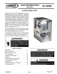
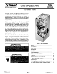
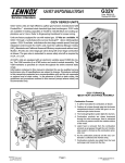
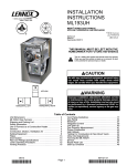
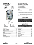
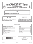
GAS FURNACES
G43UF
MERIT® SERIES
Up−Flow
ENGINEERING DATA
Bulletin No. 210394
August 2005
Supersedes December 2004
AFUE − up to 92.1%
Input − 44,000 to 132,000 Btuh
Nominal Add−on Cooling − 2 to 5 Tons
MODEL NUMBER IDENTIFICATION
G 43 UF − 24 B − 045
Unit Type
G = Gas Furnace
Series
43 = 90% Minimum AFUE
Nominal Gas Heat Input
045 = 44,000 Btuh (12.9 kW)
070 = 66,000 Btuh (19.3 kW)
090 = 88,000 Btuh (25.8 kW)
110 = 110,000 Btuh (32.2 kW)
135 = 132,000 Btuh (38.7 kW)
Configuration
UF = Up−Flow
Nominal Add−On Cooling Capacity
24 = 2 tons (7.0 kW)
36 = 3 tons (10.5 kW)
48 = 4 tons (14.10 kW)
60 = 5 tons (17.5 kW)
1 Cabinet
Width
B = 17−1/2 in. (445 mm)
C = 21 in. (533 mm)
D = 24−1/2 in. (622 mm)
1 Indoor coils with the same letter designation
will physically match the furnace.
FEATURES
CONTENTS
Blower Data . . . . . . . . . . . . . . . . . . . . . . . . . . . . . . . . Pages 13−15
Dimensions . . . . . . . . . . . . . . . . . . . . . . . . . . . . . . . . . . Pages 9−12
Exhaust Pipe Venting Information . . . . . . . . . . . . . . . . . . . Page 7
Features and Options . . . . . . . . . . . . . . . . . . . . . . . . . . Pages 2−4
Filter Air Resistance . . . . . . . . . . . . . . . . . . . . . . . . . . . . . . Page 8
High Altitude Information . . . . . . . . . . . . . . . . . . . . . . . . . . Page 8
Installation Clearances . . . . . . . . . . . . . . . . . . . . . . . . . . . . Page 8
Model Number Identification . . . . . . . . . . . . . . . . . . . . . . . Page 1
Optional Accessories Selection table . . . . . . . . . . . . . . . . Page 6
Specifications . . . . . . . . . . . . . . . . . . . . . . . . . . . . . . . . . . . . Page 5
B
D
E
WARRANTY
Duralok Plus® Aluminized Steel Heat Exchanger − Twenty
years limited warranty.
All other covered components − Five years limited warranty.
Refer to Lennox Equipment Limited Warranty certificate
included with equipment for details.
APPROVALS
Units certified by CSA International and ratings are certified by
GAMA.
Units tested and rated according to US DOE test procedures and
FTC labeling regulations.
Blower data from unit tests conducted in Lennox Laboratory air
test chamber.
Approved by the California Energy Commission and meets
California Seasonal Efficiency requirements and California
Nitrogen Oxides (NOx) Standards.
ENERGY STAR® certified units are designed to use less energy,
help save money on utility bills, and help protect the
environment.
ISO 9001 Registered Manufacturing Quality System.
K
G
N
C
F
P
O
H
I
L
J
M
APPLICATIONS
Input capacities of 44,000, 66,000, 88,000, 110,000, and
132,000 Btuh (12.9, 19.3, 25.8, 32.2, and 38.7 kW).
Energy efficiency (AFUE) up to 92.1%.
Compact cabinet with either side or bottom return air entry.
Lennox add-on indoor coils, high−efficiency air cleaners and
humidifiers can easily be added to furnace.
Shipped factory assembled with all controls installed and wired.
Each unit factory test operated to ensure proper operation.
DIRECT VENT / NON−DIRECT VENT
Furnace can be installed in either Direct Vent or Non−Direct
applications. In Direct Vent applications, combustion air is
supplied from outdoors and flue gases are discharged outdoors.
In Non−Direct Vent applications, combustion air is supplied from
indoors and flue gases are discharged outdoors.
OPTIONS
Termination Kits
Facilitates installation of combustion air intake pipe and flue
exhaust pipe.
Refer to venting table in this bulletin to determine pipe size
needed and proper termination kit required.
See Specifications table and dimension drawings.
Termination Kit − Concentric − Direct Vent Applications
Only
1−1/2, 2, or 3 inch (38, 51, or 76 mm) kit contains concentric
termination assembly, reducer bushing and 45 degree elbow.
Kit requires single hole penetration of roof or wall for installation.
Roof Termination Flashing Kit is available for use with 1−1/2 and
2 inch Kits.
CSA certified.
G43UF / Page 2
Termination Kits − Wall Assembly
Close Couple − Direct Vent Applications Only
2 or 3 inch (51 or 76 mm) kit consists of close-couple,
side-by-side PVC piping with galvanized steel wall cover plate
for sealing and isolating piping penetration of the wall.
Piping spacing and length is sized for proper wall installations.
CSA certified.
Close Couple WTK − Direct Vent Applications Only
2 or 3 inch (51 or 76 mm) kit contains one insulated faceplate,
one insulated exhaust pipe, elbow and fittings.
Wall Ring − Direct or Non−Direct Vent
2 inch (51 mm) kit contains 2 stainless steel outside seal caps, 2
galvanized steel inside seal caps, 4 seal rings for the caps and
18 inch (457 mm) insulation sleeve for sealing and isolating
intake and exhaust piping penetration of wall.
Maintain a maximum of 6 inches (152 mm) between the inlet
and outlet openings in the installation of the pipes.
Roof Termination Flashing Kit − Direct or Non−Direct Vent
2 or 3 inch (51 or 76 mm) kit contains two neoprene rubber roof
flashings for vertical venting through a roof.
Vent pipe and insulation not furnished. Each kit contains
enough parts for two non−direct vent installations.
Also available for use with 1−1/2 inch (use 2 inch flashing) and 2
inch (use 3 inch flashing) Concentric Vent Termination Kits used
in vertical venting rooftop applications.
FEATURES
B HEATING SYSTEM®
C
D
E
F
G
Lennox Duralok Plus Heat Exchanger Assembly
Lennox developed heat exchanger assembly consists of primary
heat exchanger and secondary condenser coil assembly.
Main 3-pass clamshell type heat exchanger constructed of
heavy−gauge, aluminized steel.
Designed for normal expansion and contraction.
Crimped seam design and construction provides maximum
efficiency and minimum resistance to airflow.
Secondary heat exchanger condenser coil constructed of
aluminum fins fitted to stainless steel tubes.
Coil is factory tested for leaks.
Condensate drain header box assembly located on front of coil.
Compact size of complete heat exchanger assembly permits low
overall design of furnace cabinet.
All components mounted in a heavy−gauge steel frame.
Heat exchanger assembly has been laboratory life cycle tested.
Lennox Designed Header Box
Header box on end of condenser coil collects flue condensate for
disposal through condensate collars.
Hose connects the header box drains to the condensate collars.
The condensate collars are located on each side of the cabinet
for easy field installation of condensate drain trap. Only one
collar is used, the other is plugged.
Condensate drain trap is included with the unit for field installation.
Lennox Designed Flue Condensate Trap Assembly
Condensate trap assembly is mounted outside the conditioned
air stream.
Assembly can be mounted on either side of cabinet. See
Installation Instructions.
Connection can be made with field provided 1/2 in. PVC pipe, 3/4 in.
PVC coupling, or 1−1/4 in. OD x 1 in. ID vinyl tubing with hose clamp.
Easy to clean and winterize.
Inshot Burners
Aluminized steel inshot burners provide efficient, trouble−free
operation.
Burner venturi mixes air and gas in correct proportion for proper
combustion.
Burner assembly is removable from the unit as a single
component for ease of service.
Hot Surface Mini−Nitride Ignitor
Unique, non−porous, high strength proprietary ceramic material
provides long life and trouble−free maintenance.
Low mass element provides fast heat−up and consistent igniter
temperature with low power usage.
Cemented to alumina block for positive mounting and protection
against current leakage.
High temperature Teflon® insulated ignition lead wires for
dependable operation.
Gas Control Valve
24 volt redundant combination gas control valve combines
manual shut off valve (On−Off), automatic electric valve (dual)
and gas pressure regulation into a compact combination control.
Combustion Air Inducer
Shaded pole heavy−duty blower prepurges heat exchanger and
safely vents flue products.
Pressure switch proves blower operation before allowing gas
valve to open.
Operates only during heating cycle.
Limit Control
Automatic reset, primary limit is accurately located.
Factory installed on vestibule panel on all units.
Flame Rollout Switch
Manual reset switches are factory installed on burner box.
Switch provides protection from abnormal operating conditions.
OPTIONS
High Altitude Orifice Kit − Natural Gas Only
Required for all natural gas models for proper unit operation at
altitudes of 7501 to 10,000 feet (2286 to 3048 m).
Proper orifice for LPG/Propane models is included with
LPG/Propane Conversion Kit.
High Altitude Pressure Switch Kit
Required on certain units for proper unit operation on
installations above 4,500 ft. (1372 m).
LPG/Propane Conversion Kit
Required for field changeover from natural gas to LPG/Propane.
CONTROLS
H Integrated Furnace Control Board
I
J
K
Solid−state board contains all necessary controls and relays to
operate furnace.
Combustion air inducer is controlled by board. Prior to ignition, a
pre−purge cycle for 15 seconds is initiated. After the main
burners are turned off, a post−purge cycle for 5 seconds is run.
Ignition control board continuously monitors line voltage and
maintains the igniter power at a constant level to provide
consistent lighting and maximum igniter life.
Electronic flame sensor control assures safe and reliable operation.
Should loss of flame occur, flame sensor controls will initiate 4
attempts at re−ignition before locking out unit operation for 60
minutes.
Watchguard type circuit automatically resets ignition controls
after one hour of continuous thermostat demand after unit
lockout, eliminating nuisance calls for service.
Fan control consists of adjustable blower timed−off delay (60, 90,
120, 180 seconds − factory setting 90 seconds) and fixed blower
timed−on delay (45 seconds).
For air−conditioning applications, blower is automatically
energized on thermostat demand for cooling.
Two accessory terminals furnished for additional power supply
requirements for 120 volt (less than 1 amp) power humidifiers and
powered air cleaners.
Ignition control has two LED’s to indicate status and as an aid in
troubleshooting.
24 Volt Transformer
Furnished and factory installed in control box.
40VA transformer has fuse wired in series.
Field Wiring Make-up Box
Furnished for line voltage wiring.
Factory installed internally on left side of furnace.
Box may be installed internally or externally on either side of
furnace.
OPTIONS
Thermostat
See Thermostat bulletins in Controls section and Lennox Price
Book for a complete list of thermostats.
Twinning Kit
Required to operate two furnaces simultaneously.
Kit consists of twinning control and two fan sensors.
BLOWER
L
M
Multi-speed, direct drive blower.
Statically and dynamically balanced.
Resiliently mounted.
Blower assembly slides out of unit for servicing.
Blower speeds are easily changed on the integrated furnace
control board. See blower performance tables.
G43UF / Page 3
FEATURES
FILTER (NOT FURNISHED)
Filter and provisions for external mounting must be field
provided.
OPTIONS
Air Filter and Rack Kit for Side Return Air Applications
(Not for use with RAB Return Air Base)
Washable or vacuum cleanable polyurethane frame type filter
and external side return air rack available for field installation.
Available in single and ten pack kits.
Rack has filter door for easy filter servicing.
Flanges on rack allow easy duct connection.
Field installs on either side of unit cabinet.
See dimension drawing.
EZ Filter Base for Bottom Return Air Applications
Hinged door with thumbscrew for easy filter access.
Uses standard size filters (field provided).
CABINET
N
O
P
Low−profile, narrow width cabinet allows easy installation.
Heavy−gauge, cold rolled steel construction.
Pre−painted cabinet finish.
Flanges provided on supply air opening for ease of plenum
connection or alignment with indoor coil.
Cabinet is insulated with foil faced insulation on sides and back
of heating compartment.
Complete service access.
Safety interlock switch automatically shuts off power to unit
when blower compartment access door is removed.
Gas piping and electrical inlets are provided in both sides of cabinet.
Return Air Entry:
For bottom return−air entry, remove furnished bottom seal panel
from cabinet.
For side return−air entry, corners are marked on either side of
cabinet for return air cut−outs. On furnaces with side return air
and condensate trap on the same side of the cabinet, a field
fabricated transition or RAB is required to use an IAQ product
higher than 14−3/16 in. (360 mm) when installed next to the unit
and serviced from the front. IAQ products higher than 20 in. (508
mm) require a field fabricated transition. See dimension
drawings.
NOTE − 60C and 60D size units that require air volumes over
1800 cfm (850 L/s) must have one of the following:
1. Single side return air with transition, to accommodate 20 x
25 x 1 in. (508 x 635 x 25 mm) cleanable air filter, required to
maintain proper air velocity.
2. Single side return air with optional RAB Return Air Base.
3. Bottom return air.
4. Return air from both sides.
5. Bottom and one side return air.
See Blower Performance Tables for additional information.
Coil Match−up
All furnaces exactly match C33 and CX34 cased up−flow indoor
coils with same letter designation in model number. No adaptor
required. Engaging holes furnished on cabinet for alignment.
C33 uncased coils match furnaces without any overhang but
require an optional adaptor base or field fabricated transition to
match furnace opening. See C33 coil bulletin for additional
information.
G43UF / Page 4
OPTIONS
Condensate Drain Heat Cable Kits
Self-limiting wattage heat cable prevents condensate drain from
freezing in unconditioned areas.
Available in 6, 24 or 50 ft. (1.8, 7.3, or 15.2 m) lengths.
Heat Cable Tape:
66 ft. (20 m) length, 1/2 in. (13 mm) wide fiberglass.
60 ft. (18 m) length, 2 in. (51 mm) wide aluminum foil.
Condensate Trap Alternate Location Kit
Allows condensate drain to be installed on the opposite side of
the furnace from the exhaust venting (up−flow applications only).
RAB Return Air Base
On furnaces with side return air and condensate trap on the
same side of the cabinet, a field fabricated transition or RAB is
required when installing an IAQ product higher than 14−3/16 in.
(360 mm) when installed next to the unit and serviced from the
front. IAQ products higher than 20 in. (508 mm) require a field
fabricated transition.
Must be used for 60C and 60D models with air volumes over
1800 cfm (850 L/s) in up−flow applications when only one side
return is required.
Cabinet is pre−painted steel to match the furnace.
See Dimension Drawing.
SPECIFICATIONS
ModelNo.
Gas
Heating
Performance
G43UF
−24B−045
G43UF
−24B−070
G43UF
−36B−070
G43UF
−36C−090
G43UF
−36C−090H
Canada Only
Input− Btuh (kW) 44,000 (12.9) 66,000 (19.3) 66,000 (19.3) 88,000 (25.8) 88,000 (25.8)
Output− Btuh (kW) 40,300 (11.8) 61,000 (17.9) 62,000 (18.2) 82,000 (24.0)
Temperature rise range − F (C)
1 AFUE
Highstatic(CSA)− in.w.g. (Pa)
Connections
in
in.
30 − 60
(18 − 36)
50 − 80
(28 − 44)
40 − 70
(22 − 39)
40 − 70
(22 − 39)
50 − 80
(28 − 44)
92.1%
90.0%
92.1%
92.1%
90.0%
.50 (124)
.50 (124)
.50 (124)
.50 (124)
.50 (124)
Intake / Exhaust Pipe (PVC)
2/2
2/2
2/2
2/2
2/2
Condensate Drain Trap (PVC pipe) − i.d.
1/2
1/2
1/2
1/2
1/2
with field supplied (PVC coupling) − o.d.
3/4
3/4
3/4
3/4
3/4
1−1/4 x 1
1−1/4 x 1
1−1/4 x 1
1−1/4 x 1
1−1/4 x 1
1/2
1/2
1/2
1/2
1/2
10 x 7
(254 x 178)
10 x 7
(254 x 178)
10 x 8
(254 x 203)
10 x 8
(254 x 203)
10 x 8
(254 x 203)
Motoroutput − hp (W)
1/5 (149)
1/5 (149)
1/3 (249)
1/3 (249)
1/3 (249)
Tons(kW) ofadd−oncooling
1.5 − 2
(5.3 − 7.0)
1.5 − 2
(5.3 − 7.0)
2−3
(8.8 − 10.5)
2−3
(7.0 − 10.5)
2−3
(7.0 − 10.5)
Air Volume Range − cfm (L/s)
465 − 1125
(220 − 530)
425 − 1020
(200 − 480)
710 − 1640
(335 − 775)
730 − 1630
(345 − 770)
730 − 1630
(345 − 770)
132 (60)
141 (64)
146 (66)
162 (74)
162 (74)
hose with hose clamp − i.d. x o.d.
GaspipesizeIPS
Indoor
Blower
81,000 (23.7)
Wheel nominal diameter x width −in.
(mm)
ShippingData − lbs. (kg) − 1 package
Electricalcharacteristics
120 volts − 60 hertz − 1 phase (less than 12 amps)
SPECIFICATIONS
ModelNo.
Gas
Heating
Performance
G43UF
−48C−110H
Canada Only
G43UF
−60C−110
G43UF
−60D−135
110,000 (32.2) 110,000 (32.2) 110,000 (32.2) 132,000 (38.7)
Output− Btuh (kW) 82,000 (24.0)
103,000 (30.2) 101,000 (29.6) 103,000 (30.2) 123,000 (36.0)
1 AFUE
40 − 70
(22 − 39)
45 − 75
(27 − 45)
50 − 80
(28 − 44)
40 − 70
(22 − 39)
45 − 75
(27 − 45)
92.1%
92.1%
90.0%
92.1%
92.1%
.50 (124)
.50 (124)
.50 (124)
.50 (124)
.50 (124)
Intake / Exhaust Pipe (PVC)
2/2
2/2
2/2
2/2
3/3
Condensate Drain Trap (PVC pipe) − i.d.
1/2
1/2
1/2
1/2
1/2
with field supplied (PVC coupling) − o.d.
3/4
3/4
3/4
3/4
3/4
1−1/4 x 1
1−1/4 x 1
1−1/4 x 1
1−1/4 x 1
1−1/4 x 1
Highstatic(CSA)− in.w.g. (Pa)
hose with hose clamp − i.d. x o.d.
GaspipesizeIPS
Indoor
Blower
G43UF
−48C−110
Input− Btuh (kW) 88,000 (25.8)
Temperature rise range − F (C)
Connections
in
in.
G43UF
−48C−090
1/2
1/2
1/2
1/2
1/2
10 x 10
(254 x 254)
10 x 10
(254 x 254)
11−1/2 x 10
(292 x 229)
11−1/2 x 10
(292 x 229)
1/2 (373)
1/2 (373)
1/2 (373)
1 (746)
1 (746)
Tons(kW) ofadd−oncooling
3−4
(10.5 − 14.0)
3−4
(10.5 − 14.0)
3−4
(10.5 − 14.0)
4−5
(14.0 − 17.5)
4−5
(14.0 − 17.5)
Air Volume Range − cfm (L/s)
950 − 2180
(450 − 1030)
885 − 2160
(420 − 1020)
885 − 2160
(420 − 1020)
1470 − 2720
(695 − 1285)
1440 − 2730
(680 − 1290)
178 (81)
178 (81)
186 (84)
203 (92)
Wheelnominaldiameter xwidth −in.
10 x 10
(mm) (254 x 254)
Motoroutput − hp (W)
ShippingData − lbs. (kg) − 1 package
Electricalcharacteristics
168 (76)
120 volts − 60 hertz − 1 phase (less than 12 amps)
NOTE − Filters and provisions for mounting are not furnished and must be field provided.
1 Annual Fuel Utilization Efficiency based on DOE test procedures and according to FTC labeling regulations. Isolated combustion system rating for non−weatherized furnaces
G43UF / Page 5
OPTIONAL ACCESSORIES − MUST BE ORDERED EXTRA
B" Width Models
C" Width Models
D" Width Models
87L96 − 18 x 25 x 1
(457 x 635 x 25)
87L97 − 20 x 25 x 1
(508 x 635 x 25)
87L98 − 25 x 25 x 1
(635 x 635 x 25)
Single
Ten Pack
Size of filter − in. (mm)
44J22
66K63
16 x 25 x 1
(406 x 635 x 25)
44J22
66K63
16 x 25 x 1
(406 x 635 x 25)
44J22
66K63
16 x 25 x 1
(406 x 635 x 25)
Catalog No. − Ship. Wt. − lbs. (kg)
Size of field provided filter − in.
(mm)
73P56 − 7 (3)
16 x 25 x 1
(406 x 635 x 25)
73P57 − 8 (4)
20 x 25 x 1
(508 x 635 x 25)
73P58 − 10 (5)
24 x 24 x 1
(610 x 610 x 25)
11M60
56J18
76M88
11M61
56J18
74M74
11M62
56J18
74M75
26K68
26K69
26K70
39G04
39G03
76M20
26K68
26K69
26K70
39G04
39G03
76M20
26K68
26K69
26K70
39G04
39G03
76M20
15L38
15L38
15L38
FILTER KITS
1
Air Filter and
Rack Kit
Horizontal (end)
Size of filter − in.
(mm)
Side Return
EZ Filter Base
CABINET ACCESSORIES
Down−Flow Additive Base
Horizontal Support Frame Kit
Return Air Base
CONDENSATE DRAIN KITS
6 ft. (1.8 m)
24 ft. (7.3 m)
50 ft. (15.2 m)
Fiberglass − 1/2 in. x 66 ft.
Heat Cable Tape
p
Aluminum foil − 2 in. x 60 ft.
Condensate Trap Alternate Location Kit − Up−Flow Only
Condensate Drain Heat Cable
CONTROLS
Twinning Kit
TERMINATION KITS − See Installation Instructions for specific venting information.
4 Termination
Kits
Kit
Direct Vent
Applications
Only
2, 4 Termination
Kit − Direct
Di t or
Kits
Non−Direct Vent
1−1/2 in. (38 mm)
2 in. (51 mm)
3 in. (76 mm)
2 in. (51 mm)
Wall − Close
C
Couple
l
3 in. (76 mm)
Close Couple WTK − 2 in. (51 mm)
3 in. (76 mm)
Roof
2 in. (51 mm)
Wall − Wall Ring
2 in (51 mm)
Kit
Concentric
4 Roof
Termination Flashing Kit − Direct or Non−Direct
Vent − Contains two flashings.
1
2
3
71M80
−−−
−−−
22G44
44J40
30G28
81J20
15F75
15F74
−−−
69M29
60L46
−−−
44J40
−−−
81J20
15F75
15F74
−−−
−−−
60L46
−−−
44J40
−−−
81J20
3 15F74
44J41
44J41
44J41
−−−
Cleanable polyurethane frame type filter.
Kits contain enough parts for two, non−direct vent installations.
Non−direct vent only.
GAS HEAT ACCESSORIES
1 High
1
Input
Altitude
Orifice Kit
Natural Gas Only
−045
−070
−090
−110
−135
59M16
59M16
59M16
59M16
59M16
High Altitude Pressure
Switch Kit
4501−7500 ft.
(1372−2286 m)
7501−10,000 ft.
(2286−3048 m)
0−7500 ft.
(0−2286 m)
7501−10,000 ft.
(2286−3048 m)
−−−
56M05
75M20
75M20
56M04
95M22
56M06
56M07
56M07
60M35
83M74
83M74
83M74
83M74
83M74
83M75
83M75
83M75
83M75
83M75
Required for proper operation at altitudes from 7501 to 10,000 ft. (2286 to 3048 m).
G43UF / Page 6
LPG/Propane Kit
EXHAUST PIPE VENTING TABLE
1
Altitude
0 − 2000 ft.
(0 − 609 m))
2001 − 4500 ft.
(610 − 1371 m))
4501 − 7500 ft.
(1372 − 2286 m))
7501 − 10,000
ft.
,
(2287 − 3048 m))
Vent Size
(
)
(diameter)
2 in.
2−1/2 in.
3 in.
4 in.
2 in.
2−1/2 in.
3 in.
4 in.
2 in.
2−1/2 in.
3 in.
4 in.
2 in.
2−1/2 in.
3 in.
4 in.
Maximum Equivalent Vent Length − One or Two Pipe Applications
2 G43UF−48C−110
G43UF−24B−070
G43UF−36C−090
3 G43UF−60D−135
G43UF−24B−045
2 G43UF−60C−110
G43UF−36B−070
G43UF−48C−090
ft.
110
135
160
250
110
135
160
250
110
135
160
250
110
135
160
250
m
34
41
49
76
34
41
49
76
34
41
49
76
34
41
49
76
ft.
70
135
160
250
70
135
160
250
70
135
160
250
70
135
160
250
m
21
41
49
76
21
41
49
76
21
41
49
76
21
41
49
76
ft.
50
100
125
225
50
100
125
225
30
100
125
225
n/a
100
125
225
m
15
31
38
69
15
31
38
69
9
31
38
69
n/a
31
38
69
ft.
30
70
125
200
20
70
125
200
n/a
70
125
200
n/a
70
125
200
m
9
21
38
61
6
21
38
61
n/a
21
38
61
n/a
21
38
61
ft.
n/a
n/a
4 125
180
n/a
n/a
4 90
180
n/a
n/a
4 90
180
n/a
n/a
4 90
180
m
n/a
n/a
4 38
55
n/a
n/a
4 27
55
n/a
n/a
4 27
55
n/a
n/a
4 27
55
NOTE − Minimum Equivalent Vent Pipe length is 15 feet (4.6 m).
1 Maximum Equivalent Vent Length" permitted is defined as Total Length (linear feet) of vent pipe, plus equivalent length (ft.) of fittings, plus equivalent length (ft.) of termination".
2 110 models must have the supplied 90° street ell installed directly into the unit flue collar. The street ell must be included in the elbow count.
3 135 models must have 3 in. to 2 in. reducing elbow (supplied) installed directly into the flue collar. Reducing ell must be included in elbow count.
4 90 elbows must be limited to 3 in. sweep type elbows.
VENTING NOTES One 90elbow is equivalent to 5 feet (1.5 m) of straight vent pipe.
Two 45 elbows are equal to one 90 elbow.
One 45 elbow is equivalent to 2.5 feet (.75 m) of straight vent pipe.
Wall and roof termination (non−concentric) exhaust pipe must terminate with reducer to improve exhaust velocity away from intake piping.
045 and 070 − 2, 2−1/2, 3 or 4 in. − terminate with 1−1/2 in. pipe
090 − 2, 2−1/2, 3 or 4 in. − terminate with 2 in. pipe
110 − 2, 2−1/2, 3 or 4 in. − terminate with 2 in. pipe
135 − 3 or 4 in. − terminate with 2 in. pipe
TERMINATION KITS − EQUIVALENT VENT LENGTHS
Vent Pipe Equivalent Length − ft. (m)
Heat
Size
045
−045
−070
070
−090
090
−110
110
135
−135
1
2
3
Concentric
Kits
Vent Pipe
Diameter
Close Couple
Kits
1−1/2 in.
(38 mm)
2 in.
(51 mm)
3 in.
(76 mm)
2 in.
(51 mm)
3 in.
(76 mm)
Wall Ring
Kit
Outdoor Exhaust
Accelerator
(Diameter X Length)
2 in.
(51 mm)
1−1/2 x 12 in.
2 x 12 in.
(38 x 305 mm) (51 x 305 mm)
22G44
44J40
30G28 (WTK) 81J20 (WTK)
in.
mm
71M80
69M29
60L46
2
2−1/2
3
4
2
2−1/2
3
4
2
2−1/2
3
4
2
2−1/2
3
4
3
51
64
76
102
51
64
76
102
51
64
76
102
51
64
76
102
76
12 (3.6)
15 (4.6)
21 (6.4)
42 (12.8)
12 (3.6)
15 (4.6)
24 (7.3)
42 (12.8)
not allowed
not allowed
not allowed
not allowed
not allowed
not allowed
not allowed
not allowed
not allowed
not allowed
not allowed
not allowed
not allowed
not allowed
not allowed
not allowed
not allowed
3 (1)
6 (1.8)
6 (1.8)
12 (3.7)
3 (1)
6 (1.8)
6 (1.8)
12 (3.7)
not allowed
not allowed
not allowed
not allowed
not allowed
not allowed
not allowed
not allowed
not allowed
3 (1)
6 (1.8)
6 (1.8)
12 (3.7)
3 (1)
6 (1.8)
6 (1.8)
12 (3.7)
15 (4.6)
4 (1.2)
5 (1.5)
7 (2.1)
14 (4.3)
4 (1.2)
5 (1.5)
8 (2.4)
14 (4.3)
not allowed
not allowed
not allowed
not allowed
not allowed
not allowed
not allowed
not allowed
not allowed
4 (1.2)
5 (1.5)
1 7 (2.1)
1 14 (4.3)
1 4 (1.2)
1 5 (1.5)
1 8 (2.4)
1 14 (4.3)
1 (0.3)
2 (0.6)
2 (0.6)
4 (1.2)
1 (0.3)
2 (0.6)
2 (0.6)
4 (1.2)
6 (1.8)
4
102
not allowed not allowed
25 (7.6)
not allowed
10 (3.0)
1
1
15F74
−−−
−−−
4 (1.2)
5 (1.5)
7 (2.1)
14 (4.3)
4 (1.2)
5 (1.5)
8 (2.4)
14 (4.3)
2 1 (0.3)
2 2 (0.6)
2 2 (0.6)
2 4 (1.2)
2 1 (0.3)
3 2 (0.6)
3 2 (0.6)
3 4 (1.2)
3 6 (1.8)
4 (1.2)
5 (1.5)
7 (2.1)
14 (4.3)
4 (1.2)
5 (1.5)
8 (2.4)
14 (4.3)
not allowed
not allowed
not allowed
not allowed
not allowed
not allowed
not allowed
not allowed
not allowed
not allowed
not allowed
not allowed
not allowed
not allowed
not allowed
not allowed
not allowed
1 (0.3)
2 (0.6)
2 (0.6)
4 (1.2)
1 (0.3)
2 (0.6)
2 (0.6)
4 (1.2)
6 (1.8)
not allowed
10 (3.0)
3
10 (3.0)
Requires field provided 1−1/2 in. (38 mm) outdoor exhaust accelerator.
Requires field provided 2 in. (51 mm) outdoor exhaust accelerator.
For use only in non−direct vent applications, when snow riser is not required. Requires field provided 2 in. (51 mm) outdoor exhaust accelerator.
G43UF / Page 7
FILTER AIR RESISTANCE
HIGH ALTITUDE INFORMATION
For 1 Inch (25 mm) Cleanable Filter (Field Provided)
cfm
L/s
in. w.g.
Pa
0
0
0.00
0
200
95
0.01
0
400
190
0.03
5
600
285
0.04
10
800
380
0.06
15
1000
470
0.09
20
1200
565
0.12
30
1400
660
0.15
35
1600
755
0.19
45
1800
850
0.23
55
2000
945
0.27
65
2200
1040
0.33
80
2400
1130
0.38
95
2600
1225
0.44
110
INSTALLATION CLEARANCES
Sides
10
0 inches (0 mm)
Top/Plenum
1 inch (25 mm)
Front
0 inches (0 mm)
Floor
Altitude − ft. (m)
0−4500 (0−1372)
3.5 (0.87)
4501−7500 (1373−2286)
7501−10000 (2287−3048)
1,2 3.5
3 LPG
Propane
Manifold Pressure
(Outlet)
in. w.g. (kPa)
2 3.5
0−4500 (0−1372)
(0.87)
(0.87)
10.0 (2.49)
4501−7500 (1373−2286)
2 10.0
(2.49)
7501−10,000 (0−3048)
2 10.0
(2.49)
1
2
High Altitude Orifice Kit required, see Gas Heat Accessories table for order number.
High Altitude Pressure Switch Kits as required, see Gas Heat Accessories table for
order number.
3 LPG/Propane conversion kit required, see Gas Heat Accessories table for order
number.
INSTALLATION CONFIGURATIONS
AIR FLOW
VENT
PIPING
24 inches (610 mm)
HEAT
EXCHANGER
2 Combustible
NOTE − Air for combustion and supply air ventilation must conform to the methods
outlined in American National Standard (ANSI-Z223.1) National Fuel Gas Code or
National Standard of Canada CAN/CGA-149.1, & CAN/CGA-149.2 Installation Code
for Gas Burning Appliances".
NOTE−In the U.S. flue sizing must conform to the methods outlined in current
GAMA/A.G.A. venting tables, American National Standard (ANSI-Z223.1) National
Fuel Gas Code or applicable provisions of local building codes. In Canada flue sizing
must conform to the methods outlined in National Standard of Canada
CAN/CGA-149.1 and .2.
1 Allow proper clearances to accommodate condensate trap and vent pipe installation.
2 Do not install the furnace directly on carpeting, tile, or other combustible materials other
than wood flooring.
G43UF / Page 8
Fuel
Natural
inches (0 mm)
Rear
Front (service/alcove)
Pressure regulator adjustment may be required depending on
altitude. See below for proper pressure regulator setting.
CONDENSATE
DRAIN
BLOWER
NOTE − The vent
piping and condensate drain can be
moved to the other
side of the unit. Vent
piping and drain
must be installed on
the same side of the
unit with each other
unless optional Condensate Trap Alternate Location Kit is
used.
DIMENSIONS − INCHES (MM)
1
NOTE − 60C and 60D size units that require air volumes over
1800 cfm (850 L/s) must have one of the following:
a. Single side return air with transition, to accommodate
20 x 25 x 1 in. (508 x 635 x 25 mm) air filter. Required to
maintain proper air velocity.
b. Single side return air with optional RAB Return Air Base
c. Bottom return air.
d. Return air from both sides.
e. Bottom and one side return air.
SUPPLY AIR
OPENING
See Blower Performance Tables for additional information.
2 Optional
External Side Return Air Filter Kit is not for use with the
optional RAB Return Air Base.
OPTIONAL
EXTERNAL
SIDE RETURN
AIR FILTER KIT
(Either Side)
A
B
23-3/4 (603)
2
25 (635)
TOP VIEW
28−1/2
(724)
9/16
(14)
19−7/16
(494)
9/16 (14)
6−1/2
11−5/8 (295) (165)
Right
9−3/4 (248) 4−1/8
(103)
Left
2 OPTIONAL
EXTERNAL
SIDE RETURN
AIR FILTER KIT
(Either Side)
40
(1016)
COMBUSTION AIR INTAKE
(Either Side)
3−1/8
(79)
EXHAUST AIR OUTLET
(Either Side)
6−3/4
(171)
GAS PIPING INLET
(Either Side)
CONDENSATE
TRAP CONNECTION
(Either Side)
4−7/8 (124) Right
2−1/4 (57) Left
ELECTRICAL INLET
(Either Side)
2−1/2
(64)
14−3/4
(375)
18-3/4 (476)
16
(406)
23
(584)
4
(102)
14
(356)
1 OPTIONAL
RETURN CUTOUT
(Either Side)
AIR FLOW
1−15/16 (49)
5/8 (16)
C
3/4 (19)
1
23−1/2
(597)
3/4 (19)
4−1/4
(108)
Bottom Return
Air Opening
1
FRONT VIEW
Model No
No.
G43UF−24B−045
G43UF−24B−070
G43UF−36B−070
G43UF−36C−090
G43UF−48C−090
G43UF−48C−110
G43UF−60C−110
G43UF−60D−135
Bottom Return
Air Opening
SIDE VIEW
A
B
C
in.
mm
in.
mm
in.
mm
17−1/2
446
16−3/8
416
16
406
21
533
19−7/8
454
19−1/2
495
24−1/2
622
23−3/8
546
23
584
G43UF / Page 9
OPTIONAL ACCESSORY DIMENSIONS − INCHES (MM)
RAB RETURN AIR BASE (Up−Flow Applications Only)
For use with B, C, and D size furnaces only
4
(102)
CONDENSATE
TRAP
14
(356)
AIR FLOW
14
(356)
1 23
(584)
Overall
(Maximum)
4
(102)
1
1 Minimum
11 (279)
2
Unit side return Maximum
14 (356)
air Opening
FURNACE
FRONT
5
(102)
6 (152)
17−1/2 (446) RAB−B−6 (76M88)
21 (533) RAB−C−6 (74M74)
24−1/2 (622) RAB−D−6 (74M75)
OPTIONAL RAB
RETURN AIR BASE
(470)
Overall
(Maximum)
SIDE RETURN
AIR OPENINGS
(Either Side)
3/4
(19)
20−1/2 (521)
7/8
(22)
1 18−1/2
27−5/8 (702)
SIDE VIEW
FRONT VIEW
1
Both the unit return air opening and the base return air opening must be covered by a single plenum or IAQ cabinet.
Minimum unit side return air opening dimensions for units requiring 1800 cfm or more of air (W x H): 23 x 11 in. (584 x 279 mm).
The opening can be cut as needed to accommodate plenum or IAQ cabinet while maintaining dimensions shown.
Side return air openings must be cut in the field. There are cutting guides stenciled on the cabinet for the side return air
opening. The size of the opening must not extend beyond the markings on the furnace cabinet.
2 14 inches (356 mm) is the maximum size the height of the unit opening can be cut. This may interfere with the condensate drain
(if located on the same side of the unit as the opening).
To minimize pressure drop, the largest opening height possible (up to 14 inches) is preferred.
NOTE− Optional Side Return Air Filter Kits are not for use with RAB Return Air Base.
DIMENSIONS − INCHES (MM) − FURNACE/COIL COMBINED DIMENSIONS
Cased
A
in. mm
Model No
UP−FLOW POSITION
A
B
40
(1016)
CX34−18/24B−6F
CX34−18/24C−6F
C33−24B
C33−24C
CX34−25B−6F
CX34−30B−6F
CX34−30C−6F
CX34−31B−6F
CX34−36B−6F
CX34−36C−6F
CX34−38B−6F
CX34−42B−6F
CX34−43B−6F
CX34−43C−6F
CX34−44/48B−6F
CX34−44/48C−6F
CX34−49C−6F
CX34−50/60C−6F
CX34−60D−6F
CX34−62C−6F
CX34−62D−6F
G43UF / Page 10
Uncased (CX34 − cased only)
B
A
B
in.
mm
in.
mm
in.
mm
16−1/2 419 56−1/2 1435 13−7/8
352
53−7/8
1368
C33−25B
C33−30B
C33−30C
19−1/2 495 59−1/2 1511 15−7/8
403
55−7/8
1419
20−1/2 521 60−1/2 1537 17−3/4
451
59−3/4
1467
C33−31B
C33−36B
C33−36C
C33−38B
C33−42B
C33−43B
C33−43C
C33−44C
C33−48B
C33−48C
C33−49C
C33−50/60C
C33−60D
C33−62C
C33−62D
23−1/2
24−1/2
24−1/2
24−1/2
24−1/2
28−1/2
28−1/2
24−1/2
24−1/2
24−1/2
30−1/2
27−1/2
25−1/2
32−1/2
29−1/2
514
556
540
559
556
667
654
546
562
546
724
629
629
778
730
60−1/4
61−7/8
61−1/4
62
61−7/8
66−1/4
65−3/4
61−1/2
62−1/8
61−1/2
68−1/2
64−3/4
64−3/4
70−5/8
68−3/4
1530
1572
1556
1575
1572
1683
1670
1562
1578
1562
1740
1645
1645
1793
1746
597
622
622
622
622
724
724
622
622
622
775
699
648
826
749
63−1/2
64−1/2
64−1/2
64−1/2
64−1/2
68−1/2
68−1/2
64−1/2
64−1/2
64−1/2
70−1/2
67−1/2
65−1/2
72−1/2
69−1/2
1613
1638
1638
1638
1638
1740
1740
1638
1638
1638
1791
1715
1664
1842
1765
20−1/4
21−7/8
21−1/4
22
21−7/8
26−1/4
25−3/4
21−1/2
22−1/8
21−1/2
28−1/2
24−3/4
24−3/4
30−5/8
28−3/4
OPTIONAL ACCESSORY DIMENSIONS − INCHES (MM)
CONCENTRIC ROOF
TERMINATION APPLICATIONS
CONCENTRIC WALL
TERMINATION APPLICATIONS
FLASHING
(Not Furnished)
10-1/2
(267)
OUTSIDE
WALL
12 (305)
INTAKE
AIR
EXHAUST
AIR
EXHAUST
AIR
Minimum
Above Average
Snow
Accumulation
SHEET METAL STRAP
INTAKE
AIR
INTAKE
AIR
CLAMP
(Not Furnished)
(Clamp and sheet metal strap
must be field installed to support
the weight of the termination kit.)
12 (305)
Minimum
Above
Grade
ÉÉÉÉÉÉÉÉ
ÉÉÉÉÉÉÉÉ
CLAMP
GRADE
71M80 1−1/2 inch (38 mm)
69M29 2 inch (51 mm)
See Installation Instructions for specific usage.
60L46 3 inch (76 mm)
See Installation Instructions for specific usage.
2 x 1-1/2 in. (51 x 38 mm) 60G77
3 x 2 in. (76 x 51 mm) 33K97
REDUCER BUSHING (Furnished)
46−3/4
(1187)
37
(940)
6−1/2
(165)
INTAKE AIR
4−1/2 (114)
3 (76)
INTAKE AIR
ELBOW
(Furnished)
CLAMP
(Furnished)
EXHAUST
AIR
TERMINATION
ASSEMBLY
(Furnished)
INTAKE AIR
ELBOW
(Field Supplied)
EXHAUST
AIR
TERMINATION
ASSEMBLY
(Furnished)
WALL ASSEMBLY TERMINATION KIT − RING KIT
15F74 − 2 inch (51 mm)
See Installation Instructions for specific usage.
DIRECT VENT APPLICATION
NOTE − 12 in. (305 mm) minimum height above
average snow accumulation.
NON−DIRECT VENT APPLICATION
NOTE EXHAUST PIPE SHOWN
Kit Contains Enough Parts For Two Installations
NOTE 12 in. (305 mm) minimum height above
average snow accumulation.
12 in. (305 mm) maximum
without support
8 in. (203 mm)
minimum
12 in. (305 mm) maximum
without support
6 in. (152 mm)
maximum
G43UF / Page 11
OPTIONAL ACCESSORY DIMENSIONS − INCHES (MM)
DIRECT VENT APPLICATIONS
WALL TERMINATION KITS (CLOSE-COUPLE) − 22G44 − 2 inch (51 mm) or 44J40 − 3 inch (76 mm)
See Installation Instructions for specific usage.
If Intake and Exhaust Pipe is less than
12 in. (305 mm) above snow accumulation or other obstructions, field fabricated piping must be installed.
EXHAUST
AIR
12
(305)
INSULATION
(Not Furnished)
INTAKE
AIR
INTAKE
AIR
EXHAUST
AIR
5 (127)
ÉÉÉÉÉÉÉÉÉÉÉÉ
ÉÉÉÉÉÉÉÉÉÉÉÉ
5-1/2
(140)
GRADE
2
(51)
12
(305)
12 (305)
Minimum
ÉÉÉÉÉÉÉÉÉÉÉÉÉÉ
ÉÉÉÉÉÉÉÉÉÉÉÉÉÉ
12
(305)
ABOVE GRADE
GRADE
WTK WALL ASSEMBLY TERMINATION KIT WITH FIELD FABRICATED ABOVE GRADE EXTENDED CLEARANCE
30G28 − 2 inch (51 mm) or 81J20 − 3 inch (76 mm)
If Intake and Exhaust Pipe is less than
12 in. (305 mm) above snow accumulaSee Installation Instructions for specific usage.
tion or other obstructions, field fabricated piping must be installed.
EXHAUST
AIR
12
(305)
INSULATION
(Not Furnished)
INTAKE
AIR
EXHAUST
AIR
INTAKE
AIR
5
(127)
8 (203)
Minimum
5-1/2
(140)
ÉÉÉÉÉÉÉÉÉÉÉÉ
GRADE
G43UF / Page 12
12 (305)
Maximum
12 (305)
Minimum
ABOVE GRADE
ÉÉÉÉÉÉÉÉÉÉÉÉÉÉ
GRADE
BLOWER/WATTS DATA
G43UF−24B−045 PERFORMANCE (Less Filter)
External Static
Pressure
High
in. w.g.
Pa
cfm
L/s
Watts
0.00
0
1125
530
425
0.10
25
1115
525
410
0.20
50
1090
515
395
0.30
75
1060
500
380
0.40
100
1020
480
365
0.50
125
970
460
345
0.60
150
920
435
335
0.70
175
860
405
315
0.80
200
760
360
295
0.90
225
675
320
275
Air Volume / Watts at Different Blower Speeds
Medium−High
Medium−Low
cfm
L/s
Watts
cfm
L/s
Watts
900
425
360
745
350
295
905
425
350
760
360
285
895
420
335
755
355
280
880
415
325
740
350
270
860
405
315
720
340
260
835
395
300
700
330
255
795
375
290
665
315
240
730
345
270
620
295
230
665
315
250
560
265
215
585
275
230
495
235
200
G43UF−24B−070 PERFORMANCE (Less Filter)
External Static
Pressure
High
in. w.g.
Pa
cfm
L/s
Watts
0.00
0
1115
525
435
0.10
25
1115
525
425
0.20
50
1100
520
415
0.30
75
1080
510
400
0.40
100
1050
495
385
0.50
125
1010
475
365
0.60
150
980
460
355
0.70
175
930
440
340
0.80
200
855
405
320
0.90
225
770
365
295
cfm
690
695
685
675
665
640
600
565
510
465
Low
L/s
325
330
325
320
315
300
285
265
240
190
Watts
265
260
255
250
240
230
220
215
200
175
Air Volume / Watts at Different Blower Speeds
Medium−High
Medium−Low
cfm
L/s
Watts
cfm
L/s
Watts
875
415
360
720
340
290
865
410
350
725
340
285
870
410
335
730
345
280
870
410
330
725
340
270
855
405
320
715
335
265
835
395
310
695
330
255
810
380
295
675
320
250
770
365
285
640
300
235
720
340
270
585
275
220
650
305
250
525
245
205
cfm
665
670
665
655
645
625
600
565
520
465
Low
L/s
315
315
315
310
305
295
285
265
245
220
Watts
255
255
250
240
240
230
225
215
200
190
G43UF−36B−070 PERFORMANCE (Less Filter)
Air Volume / Watts at Different Blower Speeds
External Static
Pressure
Medium−High
Medium−Low
High
in. w.g.
Pa
cfm
L/s
Watts
cfm
L/s
Watts
cfm
L/s
Watts
0.00
0
1640
775
660
1415
665
575
1160
545
485
0.10
25
1600
755
635
1395
660
550
1160
545
460
0.20
50
1540
725
605
1370
650
525
1160
545
445
0.30
75
1495
705
580
1345
635
505
1145
540
425
0.40
100
1420
670
545
1275
605
480
1125
530
395
0.50
125
1360
640
525
1245
590
450
1080
510
375
0.60
150
1275
600
490
1165
550
410
1025
485
350
0.70
175
1170
555
465
1085
515
385
965
430
335
0.80
200
1080
510
440
1010
475
360
865
410
310
0.90
225
945
445
400
840
395
320
765
360
275
cfm
1005
1000
995
990
965
945
900
860
775
710
Low
L/s
475
470
470
465
455
445
425
405
365
335
Watts
410
385
375
365
345
325
305
295
270
245
G43UF−36C−090(H) PERFORMANCE (Less Filter)
Air Volume / Watts at Different Blower Speeds
External Static
Pressure
Medium−High
Medium−Low
High
in. w.g.
Pa
cfm
L/s
Watts
cfm
L/s
Watts
cfm
L/s
Watts
0.00
0
1630
770
745
1360
640
635
1125
530
540
0.10
25
1620
765
715
1365
645
610
1160
545
515
0.20
50
1590
750
680
1365
645
580
1160
545
495
0.30
75
1550
730
655
1355
640
565
1170
550
475
0.40
100
1520
715
630
1330
630
545
1160
545
460
0.50
125
1465
690
605
1300
615
515
1140
540
440
0.60
150
1415
670
570
1250
590
490
1095
515
420
0.70
175
1350
635
545
1215
575
470
1065
500
400
0.80
200
1260
595
510
1140
540
440
1005
475
375
0.90
225
1165
550
475
1035
485
395
900
425
335
cfm
975
1000
990
985
980
960
940
905
850
730
Low
L/s
460
470
465
465
460
455
445
425
400
345
Watts
440
430
405
395
380
360
350
335
310
285
NOTES − All air data is measured external to unit without filter (not furnished − field provided).
Air volume based on bottom air return air. Actual air volume may vary on side return air applications.
G43UF / Page 13
BLOWER/WATTS DATA
G43UF−48C−090 PERFORMANCE (Less Filter)
Air Volume / Watts at Different Blower Speeds
External Static
Pressure
Medium−High
Medium−Low
High
in. w.g.
Pa
cfm
L/s
Watts
cfm
L/s
Watts
cfm
L/s
Watts
0.00
0
2180
1030
930
1835
865
790
1520
715
630
0.10
25
2135
1005
885
1825
860
750
1510
710
610
0.20
50
2085
985
840
1810
855
720
1505
710
580
0.30
75
2030
955
800
1775
835
685
1500
705
565
0.40
100
1940
915
760
1735
820
650
1480
700
535
0.50
125
1865
880
725
1660
785
600
1430
675
505
0.60
150
1740
820
670
1590
750
575
1380
650
475
0.70
175
1645
775
640
1475
695
520
1290
610
450
0.80
200
1540
725
600
1340
630
465
1175
555
405
0.90
225
1335
630
540
1170
555
440
1070
505
375
G43UF−48C−110(H) PERFORMANCE (Less Filter)
Air Volume / Watts at Different Blower Speeds
External Static
Pressure
Medium−High
Medium−Low
High
in. w.g.
Pa
cfm
L/s
Watts
cfm
L/s
Watts
cfm
L/s
Watts
0.00
0
2160
1020
880
1880
890
755
1490
705
602
0.10
25
2100
990
850
1855
875
730
1480
700
585
0.20
50
2035
960
805
1815
860
690
1475
695
560
0.30
75
1965
925
750
1755
830
650
1475
695
545
0.40
100
1885
890
725
1715
810
625
1465
690
510
0.50
125
1780
840
680
1630
770
580
1420
670
490
0.60
150
1690
800
660
1550
735
550
1360
640
460
0.70
175
1575
745
620
1410
665
505
1210
570
405
0.80
200
1375
650
550
1230
580
450
1125
530
380
0.90
225
1225
580
520
1120
530
415
1050
495
365
cfm
1280
1275
1270
1265
1250
1215
1175
1105
1020
950
Low
L/s
605
600
600
595
590
575
555
520
480
450
Watts
510
495
475
460
440
425
410
375
355
330
cfm
1235
1230
1225
1220
1215
1150
1110
1035
970
885
Low
L/s
580
580
580
575
575
540
525
490
460
420
Watts
485
475
460
445
430
400
380
350
325
310
NOTES − All air data is measured external to unit without filter (not furnished − field provided).
Air volume based on bottom air return air. Actual air volume may vary on side return air applications.
G43UF−60C−110 PERFORMANCE (Less Filter) − Single Side Return Air − Air volumes in bold require field fabricated transition to accommodate 20 x 25 x 1 in. (508 x 635 x 25 mm) air filter in order to maintain proper air velocity.
Air Volume / Watts at Different Blower Speeds
External Static
Pressure
Medium−High
Medium−Low
Low
High
in. w.g.
Pa
cfm
L/s
Watts
cfm
L/s
Watts
cfm
L/s
Watts
cfm
L/s
Watts
0.00
0
2625
1240
1350
2310
1090
1080
1885
890
885
1515
715
700
0.10
25
2570
1215
1330
2325
1095
1060
1910
900
865
1575
745
700
0.20
50
2410
1135
1305
2285
1080
1035
1930
910
845
1620
765
690
0.30
75
2425
1145
1265
2230
1055
990
1925
905
825
1635
770
675
0.40
100
2335
1100
1220
2175
1025
950
1910
900
810
1640
775
660
0.50
125
2270
1070
1195
2120
1000
935
1895
895
785
1640
775
640
0.60
150
2170
1025
1155
2045
965
885
1860
875
765
1630
770
630
0.70
175
2110
995
1130
1950
920
855
1795
845
730
1590
750
610
0.80
200
2035
960
1090
1885
890
820
1745
825
705
1540
725
580
0.90
225
1900
895
1055
1760
830
780
1665
785
680
1470
695
565
G43UF−60C−110 PERFORMANCE (Less Filter) − Bottom Return Air, Side Return Air with Optional RAB Return Air Base, Return Air from Both Sides or Return Air from Bottom and One Side.
Air Volume / Watts at Different Blower Speeds
External Static
Pressure
Medium−High
Medium−Low
Low
High
in. w.g.
Pa
cfm
L/s
Watts
cfm
L/s
Watts
cfm
L/s
Watts
cfm
L/s
Watts
0.00
0
2720
1285
1385
2410
1135
1090
2055
970
935
1620
765
710
0.10
25
2665
1255
1355
2385
1125
1075
2025
955
885
1730
815
735
0.20
50
2585
1220
1315
2350
1110
1015
2030
955
865
1680
795
690
0.30
75
2505
1180
1275
2290
1080
990
2025
955
840
1695
800
675
0.40
100
2435
1150
1250
2235
1055
940
2030
960
830
1695
800
660
0.50
125
2350
1110
1205
2170
1025
930
1975
930
790
1735
820
665
0.60
150
2255
1065
1185
2100
990
895
1915
905
765
1720
810
650
0.70
175
2160
1020
1150
2005
945
840
1865
880
730
1680
795
635
0.80
200
2020
955
1090
1905
900
825
1810
855
710
1625
765
610
0.90
225
1910
900
1050
1820
860
795
1705
805
675
1540
725
590
NOTES − All air data is measured external to unit without filter (not furnished − field provided).
G43UF / Page 14
BLOWER/WATTS DATA
G43UF−60D−135 PERFORMANCE (Less Filter) − Single Side Return Air − Air volumes in bold require field fabricated transition to accommodate 20 x 25 x 1 in. (508 x 635 x 25 mm) air filter in order to maintain proper air velocity.
Air Volume / Watts at Different Blower Speeds
External Static
Pressure
Medium−High
Medium−Low
Low
High
in. w.g.
Pa
cfm
L/s
Watts
cfm
L/s
Watts
cfm
L/s
Watts
cfm
L/s
Watts
0.00
0
2665
1260
1440
2325
1095
1100
1865
880
890
1410
665
690
0.10
25
2615
1235
1405
2310
1090
1065
1915
905
865
1465
690
685
0.20
50
2530
1195
1370
2280
1075
1055
1925
910
850
1570
740
675
0.30
75
2470
1165
1330
2235
1055
1015
1920
905
825
1590
750
670
0.40
100
2380
1125
1290
2175
1025
985
1910
900
805
1590
750
655
0.50
125
2310
1090
1265
2120
1000
965
1890
890
790
1595
755
645
0.60
150
2200
1035
1230
2055
970
935
1835
865
765
1580
745
630
0.70
175
2120
1000
1190
1970
930
900
1790
845
740
1545
730
605
0.80
200
2025
955
1160
1890
890
875
1720
810
710
1515
715
590
0.90
225
1930
910
1110
1800
850
835
1655
780
685
1440
680
570
NOTES − All air data is measured external to unit without filter (not furnished − field provided).
G43UF−60D−135 PERFORMANCE (Less Filter) − Bottom Return Air, Side Return Air with Optional RAB Return Air Base,
Return Air from Both Sides or Return Air from Bottom and One Side.
Air Volume / Watts at Different Blower Speeds
External Static
Pressure
Medium−High
Medium−Low
Low
High
in. w.g.
Pa
cfm
L/s
Watts
cfm
L/s
Watts
cfm
L/s
Watts
cfm
L/s
Watts
0.00
0
2730
1290
1465
2425
1145
1125
2055
970
915
1560
735
680
0.10
25
2670
1260
1440
2400
1135
1100
2065
975
890
1590
750
675
0.20
50
2600
1225
1400
2365
1115
1070
2045
965
865
1620
765
665
0.30
75
2525
1190
1360
2315
1095
1045
2035
960
845
1615
760
655
0.40
100
2445
1155
1325
2260
1065
1015
2020
955
820
1615
760
645
0.50
125
2360
1115
1280
2195
1035
985
1960
925
790
1610
760
635
0.60
150
2290
1080
1255
2130
1005
965
1900
895
755
1600
755
615
0.70
175
2205
1040
1220
2035
960
910
1825
860
730
1570
740
600
0.80
200
2110
995
1195
1945
915
880
1765
830
710
1540
725
580
0.90
225
1970
930
1120
1835
865
830
1680
795
690
1540
725
545
NOTES − All air data is measured external to unit without filter (not furnished − field provided).
G43UF / Page 15
Visit us at www.lennox.com
For the latest technical information, www.lennoxdavenet.com
Contact us at 1−800−4−LENNOX
NOTE − Due to Lennox’ ongoing committment to quality, Specifications, Ratings and Dimensions subject to change without notice and without incurring liability.
Improper installation, adjustment, alteration, service or maintenance can cause property damage or personal injury.
Installation and service must be performed by a qualified installer and servicing agency.
©2005 Lennox Industries Inc.