1
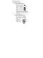
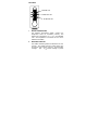
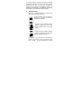
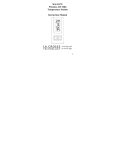
WS-7032U
Wireless 433 MHz
Miniature Weather Station
Instruction Manual
TABLE OF CONTENTS
Topic
Inventory of Contents/Additional
Equipment
Quick set-up guide
Battery installation
Features:
Indoor temperature
Weather Forecast icons & tendency
arrows
Outdoor temperature
Mounting
Troubleshooting
Maintenance and Care instructions
Specifications
Warranty
2
Page
3
4-5
6-7
8
8-10
10
11-13
14
15
16
17-18
INVENTORY OF CONTENTS
1.
2.
3.
4.
5.
WS-7032U—Weather Station.
TX6U—Remote Temperature Sensor.
Three each, ½” Philips screws.
One strip double-sided adhesive tape.
Instruction manual & Warranty card.
ADDITIONAL EQUIPMENT
1.
2.
3.
Two fresh AAA 1.5V batteries (for weather
station).
Two fresh AA 1.5V batteries (for remote
sensor)
One Philips screwdriver.
3
QUICK SET-UP GUIDE
Hint: Use good quality Alkaline Batteries and
avoid rechargeable batteries.
1.
2.
3.
4.
Have the indoor station and outdoor
remote 3 to 5 apart.
Batteries should be out of both units for
10 minutes.
Place the batteries into the outdoor
remote first then into the indoor station.
(All outdoor remotes must be started
before the indoor station)
DO NOT PRESS ANY BUTTONS
FOR 10 MINUTES.
In this time the display and sensor will start to talk to
each other and the display will show both the indoor
temperature and an outdoor temperature. If the
station does not display both temperatures after the
10 minutes please retry the set up as stated above.
After both indoor and outdoor temperatures are
displayed for 10 minutes you can place your sensor
outdoors and set your time.
4
The remote sensor should be placed in a dry, shaded
area. The remote sensor has a range of 80 feet. Any
walls that the signal will have to pass through will
reduce distance. An outdoor wall or window will
have 20 to 30 feet of resistance and an interior wall
will have 10 to 20 feet of resistance. Your distance
plus resistance should not exceed 80 ft. in a straight
line.
NOTE: Fog and mist will not harm your remote
sensor but direct rain must be avoided.
5
DETAILED SET-UP GUIDE
I.
BATTERY INSTALLATION
A.
REMOTE TEMPERATURE SENSOR
1.
2.
3.
B.
Remove
the
battery
cover. Place your thumb
over the two air-vent
Battery
slots on the face of the
Cover
Remote
Temperature
Sensor,
push
down
gently and slide the
battery cover down and
off.
Observing the correct
polarity, install 2 AA batteries. The batteries
will fit tightly (to avoid start-up problems make
sure that they do not spring free during
installation).
Replace the battery cover.
WEATHER TEMPERATURE STATION
1.
2.
Remove the battery
cover. Pull up and
out from the slot
located
in
the
central position of
the battery cover.
Observing
the
correct
polarity,
install 2 AAA
6
3.
4.
batteries. The batteries will fit tightly (to avoid
start-up problems make sure that they do not
spring free during installation).
Replace the battery cover.
To switch between °F and °C, press the
°F/°C button on the back of the unit.
Note: After the batteries have been installed into
the Weather Temperature Station the LCD
segments should light up. Also within 3 minutes,
the Outdoor Temperature should be displayed in
the OUTDOOR LCD. If any of this does not occur,
remove all batteries and install them again—
carefully observing the polarity.
C.
LOW-BATTERY & BATTERY REPLACEMENT
FEATURES
When the batteries become weak in the
Weather Temperature Station, a low battery
indicator (shaped as a battery) appears in the
LCD screen between the Hour display and
the Minute display. When you replace the
batteries in the Weather Temperature
Station, the LCD screen will continue to
display its stored information for 20 seconds.
This means that if you can install the new
batteries within this 20-second time period
you do not need to program the Station
again.
7
FEATURES
INDOOR LCD
FORECAST LCD
OUTDOOR LCD
I.
INDOOR TEMPERATURE
The Weather Temperature Station monitors the
temperature within its immediate proximity, and
displays this temperature (°F or °C) in the INDOOR
LCD. The temperature is monitored as soon as the
batteries are installed.
II.
WEATHER FORECAST
The weather forecasting feature is estimated to be 75%
accurate. The weather forecast is based solely upon
the change of air pressure over time. The WS-7032U
averages
past
air- pressure readings to provide
8
an accurate forecast—causing a necessity to disregard
all weather forecasting for 12-24 hours after the unit
has been set-up, reset, or moved from one altitude to
another (i.e. from one floor of a building to another). In
areas where the weather is not affected by the change
of air pressure, this feature will be less accurate.
A.
WEATHER ICONS
There are 3 possible weather icons that will be
displayed in the FORECAST LCD:
Sunny—indicates that the weather is
expected to improve (not that the
weather will be sunny).
Sun with Clouds—indicates that the
weather is expected to be fair (not
that the weather will be sunny with
clouds).
Clouds with Rain—indicates that the
weather is expected to get worse (not
that the weather will be rainy).
The weather icons change when the unit detects a
change in air pressure. The icons change in order
from: “sunny” to “sun with clouds” to “clouds
9
with rain,” or the reverse. It will not change from
“sunny” directly to “rainy,” although it is possible
for the change to occur quickly. If the symbols do
not change then the weather has not changed, or
the change has been too slow and gradual to
register.
B.
WEATHER TENDENCY ARROWS
Other possible displays in the FORECAST LCD
are 2 weather tendency arrows, one that points up
(under the forecast icons) and one that points
down (above the forecast icons). These arrows
reflect current changes in the air pressure. An
arrow pointing up indicates that the air pressure is
increasing and the weather is expected to improve
or remain good, an arrow pointing down indicates
that the air pressure is decreasing and the
weather is expected to become worse or remain
poor. No arrow means the pressure is stable.
II.
OUTDOOR TEMPERATURE
The Weather Temperature Station receives the outdoor
temperature (°F or °C) from the Remote Temperature
Sensor, and the temperature appears in the OUTDOOR
LCD. The Remote Temperature Sensor makes a
temperature update every 1 minute, and transmits a
new temperature to the Weather Temperature Station 3
times every 10 minutes.
MOUNTING
10
Note: Extreme and sudden changes in temperature will
decrease the accuracy of the Weather Temperature
Station, and changes in elevation will result with
inaccurate weather forecasting for the next 12 to 24
hours. These changes will require a 12 to 24 hour wait
before obtaining reliable data.
To achieve a true
temperature reading, avoid mounting where direct
sunlight can reach the Remote Temperature Sensor.
We recommend that you mount the Remote
Temperature Sensor on a North-facing wall.
The
sending range is 80ft (25m)—obstacles such as walls,
concrete, and large metal objects can reduce the range.
Place both units in their desired location, and wait
approximately 10 minutes before permanently mounting
to ensure that there is proper reception. The Weather
Temperature Station should display a temperature in the
OUTDOOR LCD within 3 minutes of setting-up.
I.
THE REMOTE TEMPERATURE SENSOR
The Remote Temperature Sensor can be mounted in
two ways:
•
with the use of screws, or
•
using the adhesive tape.
A.
MOUNTING WITH SCREWS
1.
2.
Remove the mounting bracket from the
Remote Temperature Sensor. The bracket
should snap off easily.
Place the mounting bracket over the desired
11
3.
4.
5.
B.
MOUNTING WITH ADHESIVE TAPE
1.
2.
3.
II.
location. Through the three screw holes of
the bracket, mark the mounting surface with a
pencil.
Where marked, start the screw holes into the
mounting surface.
Screw mounting bracket onto the mounting
surface. Ensure that the screws are flush
with the bracket.
Snap the Remote Temperature Sensor onto
the mounted bracket.
With a nonabrasive solution, clean and dry
the back of the mounting bracket and the
mounting surface to ensure a secure hold.
The mounting surface should be smooth and
flat.
Remove the protective strip from one side of
the tape. Adhere the tape to the designated
area on the back of the mounting bracket.
Remove the protective strip from the other
side of the tape. Position the Remote
Temperature Sensor in the desired location,
ensuring that the Weather Temperature
Station can receive the signal.
THE WEATHER STATION
The Weather Station
12
can be mounted on the wall
with the use of a wall hanging screw (not included).
A.
WALL MOUNTING
1.
2.
Place a screw (not included) into an
appropriate wall, leaving approximately 3/16
of an inch (5mm) extended from the wall.
Place the Weather Station onto the screw
using the hanging hole on the backside.
Gently pull the Station down to lock the screw
into place.
TROUBLESHOOTING
Problem:
No outdoor
temperature is displayed.
13
Solution:
Problem:
Solution:
Problem:
Solution:
1) Remove all batteries—wait 30 seconds—
then reinsert into sensor first, then into the
station.
2) Place sensor closer to station.
3) Be sure there are no obstructing objects.
4) Be sure all batteries are fresh.
The LCD screens are faint/dim.
Replace batteries.
°C is displayed instead of °F (or reverse)
Press the °F/°C button on back of station.
Note: For problems not solved, please contact La Crosse
Technology.
MAINTENANCE AND CARE INSTRUCTIONS
•
Extreme
and
14
sudden
•
•
•
•
temperature changes, vibration, and shock should
be avoided to prevent damage to the units.
Clean displays and units with a soft, damp cloth.
Do not use solvents or scouring agents; they may
mark the displays and casings.
Do not submerge in water.
Immediately remove all low powered batteries to
avoid leakage and damage.
Opening the casings invalidates the warranty. Do
not try to repair the unit.
Contact
La Crosse Technology for repairs.
15
SPECIFICATIONS
Temperature measuring range
Indoor:
Outdoor:
32°F to 104°F with 0.2°F resolution: (0°C
to 40°C with 0.1°C resolution). “OFL”
displayed if outside this range.
-21.9°F to 157.9°F with 0.2°F resolution:
(-29.9°C to 69.9°C with 0.1°C resolution).
“OFL” displayed if outside this range.
Temperature checking intervals
Indoor:
Outdoor:
Transmitting
frequency:
Temperature
transmitting
range:
Every 10 seconds.
3 times every 10 minutes.
433.92 MHz
Maximum 80ft (25m): in open space and
free from interference.
Power Source
Weather
Station:
Sensor:
2 x AAA, 1.5V (IEC LR3)
2 x AA, 1.5V (IEC LR6)
Dimensions (L x W x H)
Weather
Station:
Sensor:
2.95” x 0.83” x 7.28” (75 x 21 x 185 mm)
1.57“ x 0.9“ x 5.04“ (40 x 23 x 128 mm)
16
WARRANTY INFORMATION
La Crosse Technology, Ltd provides a 1-year limited
warranty on this product against manufacturing defects in
materials and workmanship.
This limited warranty begins on the original date of purchase,
is valid only on products purchased and used in North
America and only to the original purchaser of this product.
To receive warranty service, the purchaser must contact La
Crosse Technology, Ltd for problem determination and
service procedures. Warranty service can only be
performed by a La Crosse Technology, Ltd authorized
service center. The original dated bill of sale must be
presented upon request as proof of purchase to La Crosse
Technology, Ltd or La Crosse Technology, Ltd’s authorized
service center.
La Crosse Technology, Ltd will repair or replace this product,
at our option and at no charge as stipulated herein, with new
or reconditioned parts or products if found to be defective
during the limited warranty period specified above. All
replaced parts and products become the property of La
Crosse Technology, Ltd and must be returned to La Crosse
Technology, Ltd. Replacement parts and products assume
the remaining original warranty, or ninety (90) days,
whichever is longer. La Crosse Technology, Ltd will pay all
expenses for labor and materials for all repairs covered by
this warranty. If necessary repairs are not covered by this
warranty, or if a product is examined which is not in need or
repair, you will be charged for the repairs or examination.
17
The owner must pay any shipping charges incurred in
getting your La Crosse Technology, Ltd product to a La
Crosse Technology, Ltd authorized service center. La
Crosse Technology, Ltd will pay ground return shipping
charges to the owner of the product to a USA address only.
Your La Crosse Technology, Ltd warranty covers all defects
in material and workmanship with the following specified
exceptions: (1) damage caused by accident, unreasonable
use or neglect (including the lack of reasonable and
necessary maintenance); (2) damage occurring during
shipment (claims must be presented to the carrier); (3)
damage to, or deterioration of, any accessory or decorative
surface; (4) damage resulting from failure to follow
instructions contained in your owner’s manual; (5) damage
resulting from the performance of repairs or alterations by
someone other than an authorized La Crosse Technology,
Ltd authorized service center; (6) units used for other than
home use (7) applications and uses that this product was not
intended or (8) the products inability to receive a signal due
to any source of interference.. This warranty covers only
actual defects within the product itself, and does not cover
the cost of installation or removal from a fixed installation,
normal set-up or adjustments, claims based on
misrepresentation by the seller or performance variations
resulting from installation-related circumstances.
LA CROSSE TECHNOLOGY, LTD WILL NOT ASSUME
LIABILITY FOR INCIDENTAL, CONSEQUENTIAL,
PUNITIVE, OR OTHER SIMILAR DAMAGES ASSOCIATED
WITH THE OPERATION OR MALFUNCTION OF THIS
18
PRODUCT. THIS PRODUCT IS NOT TO BE USED FOR
MEDICAL PURPOSES OR FOR PUBLIC INFORMATION.
THIS PRODUCT IS NOT A TOY. KEEP OUT OF
CHILDREN’S REACH.
This warranty gives you specific legal rights. You may also
have other rights specific to your State. Some States do no
allow the exclusion of consequential or incidental damages
therefore the above exclusion of limitation may not apply to
you.
For warranty work, technical support, or information contact:
La Crosse Technology
2809 Losey Blvd. S.
La Crosse, WI 54601
Phone: 608.782.1610
Fax: 608.796.1020
e-mail:
[email protected]
(warranty work)
[email protected]
(information on other products)
web:
19
www.lacrossetechnology.com
FCC ID: OMO-01RX (WEATHER STATION)
OMO-01TX (SENSOR)
THIS DEVICE COMPLIES WITH PART 15 OF THE FCC
RULES. OPERATION IS SUBJECT TO THE FOLLOWING
TWO CONDITIONS:
1.
2.
THIS DEVICE MAY NOT CAUSE HARMFUL
INTERFERENCE, AND
THIS DEVICE MUST ACCEPT INTERFERENCE
RECEIVED, INCLUDING INTERFERENCE THAT
MAY CAUSE UNDESIRED OPERATION.
20