1
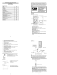
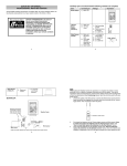
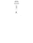
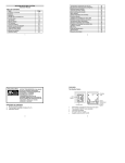
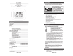
Note: When putting the Weather Station into operation,
it is important to have them in close proximity (e.g. on a
table) while completing wiring and set-up of the system.
This step is important to allow testing of all components
for correct function before placing and mounting them at
their final destinations (See Positioning below).
1.
Model WS-1913
WEATHER CENTER
2.
Quick Setup Guide
3.
INITIAL SETUP:
OPTIONAL
Wireless transmission
at 915 MHz – SelfEmptying Rain sensor
to weather station
4.
Weather Center
Wireless transmission at
915 MHz - thermo-hygro
transmitter to weather
station
5.
Rain Sensor (sold separately)
6.
Wind Sensor
7.
8.
Thermo-hygro
Transmitter
Cable connection between the wind sensor and
the thermo-hygro transmitter
1
Socket for wind
Unwind the cables of the Wind sensor. Connect
sensor
the Wind sensor to the Thermo-hygro transmitter
by plugging the connector head into the socket of
the Thermo-hygro sensor.
First insert the batteries into the Thermo-hygro sensor and optional rain sensor
(purchased separately) (See How to install and replace the batteries into the
Thermo-hygro sensor and How to install and replace the batteries into the rain
sensor (optional) below).
Then insert the batteries into the Weather Center (See How to install and replace
the batteries into the Weather Center below). Once the batteries are installed, all
segments of the LCD will light up. It will then display the time as 12:00, the date as
1.1.09, the weather icons, and air pressure value. "- - -" will be shown for outdoor
data.
The Weather Center will start receiving data from the transmitter. The transmission
reception icon will be blinking to indicate that the station is trying to get the thermohygro transmitter data. The outdoor temperature, humidity and wind data should
then be displayed on the Weather Center. If this does not happen after 135 seconds,
the batteries will need to be removed from all units. You will have to start again from
step 2.
The transmitter reception icon is now blinking again to indicate that the station is
trying to get the rain sensor data. It will stop blinking once the rain sensor has been
detected. If this does not happen after 135 seconds, you will need to start again from
step 2.
You may need to check the cable for correct connection and all the components for
correct function by manually turning the wind-gauge by moving the wind-vane; tilting
the rain sensor to hear the impact of the internal moving seesaw, etc. (see
Positioning below).
Time and date must be manually set (See Manual Setting below).
After the Weather Center has been checked for correct function with regard to the
above points and found fit, the initial set up of the weather station system is finished
and the mounting of the system components can take place. It must be ensured
2
however that all components work properly together at their chosen mounting or
standing locations.
Note: After batteries are installed in the transmitter, install the batteries in the weather
center to receive the signal from the transmitters as soon as possible. If the weather
center is powered more than 5 hours after the transmitter is powered, the weather center
will never receive the signal successfully from the transmitters. In this case, you will need
to reinstall the batteries for all the transmitters to redo the setup procedure.
After the batteries are installed, there will be synchronization between weather center and
the transmitters. At this time, the signal reception icon will be blinking. When the signal is
successfully received by the Weather Center, the icon will be switched on. (If it is not
successful, the icon will not be shown in LCD) This allows you to see whether the last
reception was successful (icon on) or not (icon off).
Short blinking of the icon shows that a reception is in progress.
HOW TO INSTALL AND REPLACE THE BATTERIES INTO THE THERMOHYGRO TRANSMITTER
The outdoor Thermo-hygro transmitter works with 2 x AA IEC LR6,
1.5V batteries. To install and replace the batteries, please follow the
steps below:
1.
Uninstall the rain cover of the transmitter.
2.
Remove the battery compartment cover.
3.
Insert the batteries, observing the correct polarity (see the
marking in the battery compartment).
4.
Replace the battery cover and the rain cover onto the unit.
Note: When changing batteries in any of the units, all units need to be reset by following
the setup procedures. This is because a random security code is assigned by the thermohygro sensor at start-up and this code must be received and stored by the weather center
in the first several minutes of power being supplied to it.
HOW TO INSTALL AND REPLACE THE BATTERIES IN THE WEATHER
STATION
The Weather Station works with 2 x C, IEC LR14, 1.5V batteries. When the batteries need
to be replaced, the low battery symbol will appear on the LCD.
To install or replace the batteries, please follow
the steps below:
1.
Remove the battery compartment cover.
2.
Insert the batteries observing the correct
polarity (see the marking in the battery
compartment).
3.
Replace the battery cover.
Transmitter signal reception icon
If the signal reception is not successful on the first frequency (915MHz) for 45 seconds,
the frequency is changed to 920MHz and the learning is tried another 45 seconds. If still
not successful, the reception is tried for 45 seconds on 910MHz. This will also be done for
re-synchronization.
Note: When changing batteries in any of the units, all units need to be reset by following
the setup procedures. This is because a random security code is assigned by the
transmitter and rain sensor (optional) at start-up and this code must be received and
stored by the Weather Station in the first 90 seconds of power being supplied to it.
Note: The stored History record will not be kept after the battery change is done on the
weather station.
3
4
FUNCTION KEYS:
LCD SCREEN
Weather Station:
The Weather Station has 4 easy-to-use function keys.
The LCD screen is split into 3 sections displaying the following information:
1.
2.
3.
SET key + key HISTORY key MIN/MAX key
SET key
x
Press and hold to enter manual setting modes: LCD contrast, Manual time setting,
12/24 hour time display, Calendar setting, ºC/ ºF temperature unit, Wind speed unit,
Rainfall unit, Pressure unit, Relative pressure reference setting, Weather tendency
threshold setting
x
Press to toggle between the display of Mode 1 or Mode 2:
Mode1: "Wind speed + outdoor temp + rel. pressure"
Mode 2: "Gust + Dew Point temp + rainfall data (only if there is a rain sensoroptional)"
(Mode 2 displayed will be shown for 30 seconds. Then it will return to normal display
x
Press to activate the reset mode when MAX or MIN record is shown
+ key
x
x
x
x
In display Mode 1, press to toggle the date, weekday, + date, Indoor temp, or sec
In display Mode 2, press to toggle the Relative Pressure, 24 hour rainfall and Total
rainfall (if there is a rain sensor- optional).
Press to adjust (increase) the level of different settings
Press to confirm to reset the MIN/MAX record
HISTORY key
x
Press to display the weather data history records or exit manual setting mode
MIN/MAX key
x
Press to display MIN/MAX records of various weather data or adjust (decrease) the
level of different settings
Time and date/ indoor temp/ second
Wind data, outdoor temperature and humidity, dew point, weather forecast icon and
tendency indicator
Air pressure history, relative air pressure, rainfall data (optional)
Calendar / indoor
temperature / seconds
display
Time display
Wind speed / gust* in
mph, km/h, m/s
Wind Chill in
ƱC or ƱF
Weather forecast
Icon
Weather tendency
indicator
Low battery indicator
(weather station)
Outdoor
temperature
/ dew point*
in qC or qF
Transmitter signal
reception icon
Outdoor relative
humidity in %
Low battery
indicator #
(transmitter)
Air pressure
history histogram
MI/MAX icons
HISTORY
icon
Low battery
indicator (rain
sensor - optional)
Relative air pressure /
24 hr rainfall / Total
rainfall display* (only if
there is a rain sensor
being used)
When the signal from the transmitter/ or Rain sensor (optional) is successfully received by
icon will not
the Weather Station, the icon will be switched on. (If not successful, the
be shown on the LCD). User can therefore easily see whether the last reception was
successful (“ON”
icon) or not (“OFF” icon). On the other hand, the short blinking of
icon shows that a reception is being done at that time.
the
* In normal display user may press the SET key shortly to toggle between Mode1 and
Mode 2 display:
5
6
Mode 1: Wind speed, outdoor temperature, relative air pressure are shown.
Wind speed icon
MOUNTING THE UNITS:
Using 915MHz wireless transmission gives users little restriction on placement because all
units can be positioned virtually anywhere within a 330 ft / 100 meters radius of the base
station. Please ensure that the cable included in this set meets your distance
requirements (see accessories in the main user manual for adding extension cables).
Important: Ensure all signals can be received and/or all cable distances meet with your
requirements at the point of fixing particularly before you start drilling any mounting holes.
Outdoor temp
icon
Wind sensor
Rel. Air Pressure icon
Transmitter signal reception icon
In Mode 1, this reception icon is showing the condition of the
reception of the signal from Thermo-hygro transmitter
Mode 2: Wind gust, dew point, and rainfall (optional) reading are shown.
Note: To view the rainfall data, press the + key after entering Mode 2 display.
Wind gust icon
Secure the main unit to the shaft of the mast holder using the single screw provided with
the front of the sensor (marked E) facing in the East-West direction otherwise wind
direction will not be accurate. Now fix the entire unit to a suitable mast using the U-bolt,
washers and nuts found in this set.
Note: For best results mount the wind sensor onto a mast to allow the wind to freely travel
from all directions to enable an accurate reading (ideal mast size should be from Ø 5/8” to
11/4”). Ensure that the cable of the wind sensor meets your distance requirements
Thermo-hygro Sensor
To wall mount the thermo-hygro sensor, fix the wall holder onto the desired wall (2 screws
are supplied), plug the sensor firmly into the wall holder and then carefully replace the rain
cover back over the thermo-hygro sensor.
Note: After mounting the units, should the weather data not be received, user may need to
remove the batteries from all units and redo the set-up procedures after about 5 minutes.
Rain sensor (optional)
Dew point icon
Rainfall icon
The rain sensor should be mounted horizontally about 2-3ft off from the ground (or higher)
in an open area away from trees or other coverings to allow rain to fall naturally for an
accurate reading.
Note: For best results ensure the base is horizontal to allow maximum drainage of any
collected rain
In Mode 2, this reception
icon is showing the
condition of the reception
of the signal from Rain
sensor (only if a rain
sensor is being used)
7
WARRANTY INFORMATION
La Crosse Technology, Ltd provides a 1-year limited warranty on this product against
manufacturing defects in materials and workmanship.
This limited warranty begins on the original date of purchase, is valid only on products
purchased and used in North America and only to the original purchaser of this product.
8
To receive warranty service, the purchaser must contact La Crosse Technology, Ltd for
problem determination and service procedures. Warranty service can only be performed
by a La Crosse Technology, Ltd authorized service center. The original dated bill of sale
must be presented upon request as proof of purchase to La Crosse Technology, Ltd or La
Crosse Technology, Ltd’s authorized service center.
La Crosse Technology, Ltd will repair or replace this product, at our option and at no
charge as stipulated herein, with new or reconditioned parts or products if found to be
defective during the limited warranty period specified above. All replaced parts and
products become the property of La Crosse Technology, Ltd and must be returned to La
Crosse Technology, Ltd.
THE OPERATION OR MALFUNCTION OF THIS PRODUCT. THIS PRODUCT IS NOT
TO BE USED FOR MEDICAL PURPOSES OR FOR PUBLIC INFORMATION. THIS
PRODUCT IS NOT A TOY. KEEP OUT OF CHILDREN’S REACH.
This warranty gives you specific legal rights. You may also have other rights specific to
your State. Some States do no allow the exclusion of consequential or incidental
damages therefore the above exclusion of limitation may not apply to you.
For warranty work, technical support, or information contact:
La Crosse Technology, Ltd
2817 Losey Blvd. S.
La Crosse, WI 54601
Replacement parts and products assume the remaining original warranty, or ninety (90)
days, whichever is longer. La Crosse Technology, Ltd will pay all expenses for labor and
materials for all repairs covered by this warranty. If necessary repairs are not covered by
this warranty, or if a product is examined which is not in need or repair, you will be
charged for the repairs or examination.
On the Web: www.lacrossetechnology.com/support
The owner must pay any shipping charges incurred in getting your La Crosse Technology,
Ltd product to a La Crosse Technology, Ltd authorized service center. La Crosse
Technology, Ltd will pay ground return shipping charges to the owner of the product to a
USA address only.
Your La Crosse Technology, Ltd warranty covers all defects in material and workmanship
with the following specified exceptions: (1) damage caused by accident, unreasonable use
or neglect (including the lack of reasonable and necessary maintenance); (2) damage
occurring during shipment (claims must be presented to the carrier); (3) damage to, or
deterioration of, any accessory or decorative surface; (4) damage resulting from failure to
follow instructions contained in your owner’s manual; (5) damage resulting from the
performance of repairs or alterations by someone other than an authorized La Crosse
Technology, Ltd authorized service center; (6) units used for other than home use (7)
applications and uses that this product was not intended or (8) the products inability to
receive a signal due to any source of interference.
This warranty covers only actual defects within the product itself, and does not cover the
cost of installation or removal from a fixed installation, normal set-up or adjustments,
claims based on misrepresentation by the seller or performance variations resulting from
installation-related circumstances.
All rights reserved. This handbook must not be reproduced in any form, even in excerpts, or duplicated or
processed using electronic, mechanical or chemical procedures without written permission of the
publisher.
This handbook may contain mistakes and printing errors. The information in this handbook is regularly
checked and corrections made in the next issue. We accept no liability for technical mistakes or printing
errors, or their consequences.
All trademarks and patents are acknowledged.
LA CROSSE TECHNOLOGY, LTD WILL NOT ASSUME LIABILITY FOR INCIDENTAL,
CONSEQUENTIAL, PUNITIVE, OR OTHER SIMILAR DAMAGES ASSOCIATED WITH
9
10
Nota: Al hacer funcionar el centro climático, es importante
tenerlo a corta distancia (por ejemplo, sobre una mesa)
mientras se finaliza el cableado y la configuración del
sistema. Este paso es importante para permitir probar que
todos los componentes funcionan correctamente antes de
colocarlos y montarlos en sus destinos finales (consulte
Colocación a continuación).
9.
Modelo WS-1913
CENTRO CLIMÁTICO
10.
Guía de configuración rápida
CONFIGURACIÓN
INICIAL:
OPCIONAL
Transmisión
inalámbrica a 915
MHz: sensor de lluvia
inalámbrico, con
vaciado automático,
para la estación
climática
Centro climático
Transmisión
inalámbrica a 915
MHz: transmisor
con termómetro e
higrómetro, para la
estación climática
11.
12.
13.
Sensor de lluvia
(se vende por separado)
Transmisor con
termómetro e
higrómetro
14.
Sensor de viento
15.
Cable de conexión entre el sensor de viento y
transmisor con termómetro e higrómetro
11
Socket para
sensor de viento
Desenrolle los cables del sensor de viento. Conecte
el sensor de viento al transmisor del termómetro e
higrómetro, enchufando el cabezal del conector en el socket del sensor del
termómetro e higrómetro.
Primero, inserte las baterías en el sensor del termómetro e higrómetro y el sensor
de lluvia opcional (se compra por separado) (consulte Cómo instalar y reemplazar
las baterías en el sensor del termómetro e higrómetro y Cómo instalar y
reemplazar las baterías en el sensor de lluvia (opcional) a continuación).
Luego, inserte las baterías en el centro climático (consulte Cómo instalar y
reemplazar las baterías en el centro climático a continuación). Una vez que las
baterías estén instaladas, se iluminarán todos los segmentos de la pantalla LCD.
Luego se mostrará la hora como las 12:00, la fecha como 1.1.09, los íconos del
clima y el valor de la presión del aire. Se mostrará "- - -" como datos del exterior.
El centro climático comenzará a recibir señales de datos desde el transmisor. El
ícono de recepción de la transmisión parpadeará para indicar que la estación está
intentando obtener los datos del transmisor del termómetro e higrómetro. Entonces
debería aparecer los datos de la temperatura exterior, la humedad y el viento en el
centro climático. Si esto no ocurre luego de 135 segundos, deberá retirar las
baterías de todas las unidades. Deberá comenzar de nuevo desde el paso 2.
El ícono de recepción del transmisor parpadeará ahora de nuevo para indicar que la
estación está intentando obtener los datos del sensor de lluvia. Dejará de parpadear
cuando se detecte el sensor de lluvia. Si esto no ocurre luego de 135 segundos,
deberá comenzar de nuevo desde el paso 2.
Es posible que deba revisar que el cable esté correctamente conectado y que todos
los componentes funcionen correctamente girando de forma manual el medidor de
viento al mover la tablilla de viento, inclinar el sensor de lluvia para escuchar el
impacto de la sube y baja moviéndose en el interior, etc. (consulte Colocación a
continuación).
Se debe configurar manualmente la hora y la fecha (consulte Configuración
manual a continuación).
12
16.
Después de revisar si el centro climático funciona correctamente con respecto a los
puntos anteriores y aprobarlos, se da por terminada la configuración inicial del
sistema del centro climático y se puede proceder con el montaje de los
componentes del sistema. Sin embargo, se debe comprobar que todos los
componentes funcionan correctamente juntos en su ubicación de montaje o
colocación elegidos.
Nota: Después de instalar las baterías en el transmisor, instale las baterías en el centro
climático para recibir la señal de los transmisores lo más pronto posible. Si el centro
climático recibe alimentación más de 5 horas después de que el transmisor la reciba, el
centro climático no recibirá nunca la señal exitosamente desde los transmisores. En este
caso, deberá reinstalar las baterías de todos los transmisores a fin de volver a realizar el
procedimiento de configuración.
Después de instalar las baterías, el centro climático y los transmisores se sincronizarán
entre sí. En este momento, el ícono de recepción de señal parpadeará. Cuando el centro
climático reciba la señal exitosamente, se encenderá este ícono. (Si no tiene éxito, el
ícono no aparecerá en la pantalla LCD.) Esto le permite consultar si la última recepción
fue exitosa (ícono encendido) o no (ícono apagado).
El parpadeo breve del ícono muestra que la recepción está en progreso.
CÓMO INSTALAR Y REEMPLAZAR LAS BATERÍAS EN EL TRANSMISOR
DEL TERMÓMETRO E HIGRÓMETRO
El transmisor del termómetro e higrómetro funciona con 2 baterías AA,
IEC LR6, de 1,5 V. Para instalar y reemplazar las baterías, siga los
pasos a continuación:
5.
Desinstale la cubierta para lluvia del transmisor.
6.
Retire la cubierta del compartimiento para las baterías.
7.
Inserte las baterías según la polaridad correcta (consulte las
marcas en el compartimiento para las baterías).
8.
Vuelva a colocar la cubierta de las baterías y la cubierta para
lluvia en la unidad.
Nota: Cuando cargue las baterías en cualquiera de las unidades, deben reestablecerse
todas las unidades siguiendo los procedimientos de configuración. Esto se debe a que el
sensor con termómetro e higrómetro asigna un código de seguridad aleatorio al arrancar y
este código debe ser recibido y almacenado por el centro climático en los primeros
minutos de suministro de alimentación.
CÓMO INSTALAR Y REEMPLAZAR LAS BATERÍAS EN LA ESTACIÓN
CLIMÁTICA
La estación climática funciona con 2 baterías C, IEC LR14, de 1,5 V. Cuando se deba
reemplazar las baterías, el símbolo de batería
baja aparecerá en la pantalla LCD.
Para instalar o reemplazar las baterías, siga los
pasos a continuación:
4.
Retire la cubierta del compartimiento para
las baterías.
5.
Inserte las baterías según la polaridad
correcta (consulte las marcas en el
compartimiento para las baterías).
6.
Coloque de nuevo la cubierta de la batería.
Ícono de recepción de
señal del transmisor
Si la recepción de la señal no es exitosa en la primera frecuencia (915 MHz) durante 45
segundos, la frecuencia se cambia a 920 MHz y se intenta reconocer durante otros 45
segundos. Si sigue sin tener éxito, la recepción se intenta durante 45 segundos a 910
MHz. También se hará esto para la volver a sincronizar.
Nota: Cuando cargue las baterías en cualquiera de las unidades, deben reestablecerse
todas las unidades siguiendo los procedimientos de configuración. Esto se debe a que el
transmisor y sensor de lluvia (opcional) asigna un código de seguridad aleatorio al
arrancar y este código debe ser recibido y almacenado por la estación climática en los
primeros 90 segundos de suministro de alimentación.
13
14
Nota: El registro histórico almacenado no se mantendrá después de realizar el cambio de
batería en la estación climática.
Tecla HISTORY
x
Presione para mostrar los registros históricos de datos del clima o salir del modo de
configuración manual
TECLAS DE FUNCIÓN:
Estación climática:
La estación climática tiene 4 teclas de función fáciles de usar.
Tecla SET
Tecla +
Tecla MIN/MAX
x
Presione para mostrar los registros MÍN./MÁX. de varios datos del clima o ajustar
(disminuir) el nivel de diferentes configuraciones
Tecla Tecla
HISTORY MIN/MAX
Tecla SET
x
Presione y mantenga para ingresar a los modos de configuración manual: Contraste
de pantalla LCD, configuración de hora manual, exhibición de hora de 12/24,
configuración del calendario, unidad de temperatura ºC/ ºF, unidad de velocidad del
viento, unidad de lluvia, unidad de presión, configuración de referencia de la presión
relativa, configuración de umbral de tendencia climática
x
Presione la tecla alternar entre la exhibición del modo 1 o el modo 2:
Modo 1: "Velocidad del viento + temperatura exterior + presión relativa"
Modo 2: "Ráfaga + temp. de punto de rocío + datos de lluvia (sólo si hay un sensor
de lluvia, opcional)"
(El modo 2 exhibido se mostrará durante 30 segundos. Luego volverá a la exhibición
normal.
x
Presione para activar el modo de reinicio cuando se muestre el registro de MÁX. o
MÍN.
Tecla +
x
En el modo de exhibición 1, presione para alternar entre fecha, día de la semana, +
fecha, temp. interior o segundos
x
En el modo de exhibición 2, presione para alternar entre presión relativa, lluvia de
24 horas y lluvia total (si hay un sensor de lluvia, opcional).
x
Presione para ajustar (aumentar) el nivel de las diferentes configuraciones
x
Presione para confirmar y restablecer todos los registros MÍN./MÁX.
15
16
La pantalla LCD está dividida en 3 secciones que muestran la siguiente información:
* Durante la exhibición normal, el usuario puede presionar la tecla SET brevemente para
alternar entre el modo de exhibición 1 y 2:
4.
5.
Modo 1: Se muestra la velocidad del viento, la temperatura exterior y la presión relativa
del aire.
PANTALLA LCD
6.
Hora y fecha / temp. interior / segundos
Datos del viento, temperatura y humedad exterior, punto de rocío, ícono de
pronóstico del clima e indicador de tendencia
Historial de presión del aire, presión relativa del aire, datos de lluvia (opcional)
Calendario /
temperatura interior
/ exhibición de
segundos
Exhibición de
la hora
Ícono de velocidad
del viento
Ícono de
temperatura
exterior
Velocidad del viento /
ráfaga* en mph, km/h,
m/s
Frialdad del
viento
en ƱC o ƱF
Ícono de presión relativa
del aire
Ícono de pronóstico
del clima
Indicador de
tendencia del
clima
Temperatura
exterior / punto de
rocío en °C o °F
Ícono de
recepción de señal
del transmisor
Histograma de
historial de
presión del aire
Indicador de batería
baja (estación
climática)
Humedad relativa
exterior en %
Indicador de batería
baja # (transmisor)
Íconos de MÍN./MÁX.
Ícono de
HISTORIAL
Indicador de
batería baja
(sensor de lluvia,
opcional)
Presión relativa del
aire / lluvia de 24
horas / exhibición de
lluvia total* (sólo si
se usa un sensor de
lluvia)
Cuando la señal desde el transmisor/o el sensor de lluvia (opcional) es recibida
exitosamente por la estación climática, se encenderá el ícono . (Si no es exitosa, el
ícono
no aparecerá en la pantalla LCD). Por lo tanto, el usuario puede ver fácilmente
si la última recepción fue exitosa (ícono "ON" ) o no (ícono "OFF" ). Por otra parte, el
parpadeo breve del ícono muestra que la recepción se está llevando a cabo en ese
momento.
17
Ícono de recepción de señal del transmisor
En el modo 1, este ícono de recepción muestra el estado de la
recepción de la señal del transmisor del termómetro e higrómetro
Modo 2: Se muestran las lecturas de la ráfaga de viento, el punto de rocío y la lluvia
(opcional).
Nota: Presione la tecla + para consultar los datos de lluvia después de entrar al modo de
exhibición 2.
Ícono de la ráfaga
de viento
Ícono del punto
de rocío
Ícono de lluvia
En el modo 2, este ícono de
recepción muestra el estado
de la recepción de la señal
del sensor de lluvia (sólo si
se usa un sensor de lluvia)
18
MONTAJE DE LAS UNIDADES:
INFORMACIÓN SOBRE LA GARANTÍA
El uso de la transmisión inalámbrica de 915 MHz permite que los usuarios tengan pocas
restricciones en la colocación, ya que todas las unidades pueden colocarse prácticamente
en cualquier lugar dentro de un radio de 91,44 m / 330 pies desde la estación base.
Asegúrese de que el cable incluido en este juego satisfaga sus requisitos de distancia
(consulte los accesorios del manual principal del usuario para añadir extensiones
eléctricas).
La Crosse Technology, Ltd proporciona 1 año de garantía limitada para este producto
contra defectos de fabricación en los materiales y la mano de obra.
Importante: Asegúrese de que todas las señales se puedan recibir y/o que todas las
extensiones de los cables satisfagan sus requisitos, hasta el punto de arreglarlos de
manera particular antes de comenzar a taladrar cualquier orificio de montaje.
Sensor de viento
Fije la unidad principal al eje del soporte del mástil, con el tornillo que se incluye con el
sensor frontal (marcado E) apuntando en dirección este-oeste, de lo contrario, la dirección
del viento no será correcta. Luego, fije la unidad completa a un mástil adecuado con el
perno en U, las arandelas y tuercas incluidos en este juego.
Nota: Para obtener los mejores resultados, monte el sensor de viento en un mástil para
permitir que el viento viaje libremente desde todas direcciones y así lograr una lectura
adecuada (el tamaño ideal del mástil debe ser entre Ø 1,59 cm y 3,18 cm). Asegúrese de
que el cable del sensor de viento cumpla con sus requisitos de distancia.
Sensor con termómetro e higrómetro
Para montar en pared el sensor con termómetro e higrómetro, fije el soporte para pared
en la pared deseada (se incluyen 2 tornillos), enchufe el sensor firmemente en el soporte
para pared y luego vuelva a colocar cuidadosamente la cubierta para lluvia sobre el
sensor con termómetro e higrómetro.
Nota: Después de montar las unidades, si no se reciben datos del clima, es posible que el
usuario deba retirar las baterías de todas las unidades y volver a realizar los
procedimientos de configuración después de aproximadamente 5 minutos.
Sensor de lluvia (opcional)
El sensor de lluvia se debe montar horizontalmente, aproximadamente a 60,96 cm a
91,44 cm del suelo (o más alto), en un área abierta, lejos de árboles u otras coberturas
para permitir que la lluvia caiga naturalmente y lograr una lectura adecuada.
Nota: Para obtener mejores resultados, asegúrese de que la base se encuentra de
manera horizontal, para permitir un desagüe máximo de la lluvia recolectada
19
Esta garantía limitada tiene vigencia a partir de la fecha de compra original, es válida sólo
para los productos comprados y utilizados en América del Norte y únicamente para el
comprador original de este producto. Para obtener el servicio de garantía, el comprador
debe ponerse en contacto con La Crosse Technology, Ltd para determinar cuál es el
problema y los procedimientos de servicio. Únicamente el centro de servicio autorizado
de La Crosse Technology, Ltd puede llevar a cabo el servicio de garantía. A solicitud de
La Crosse Technology, Ltd, se debe presentar la factura original con fecha como prueba
de la compra en La Crosse Technology, Ltd o en el centro de servicio autorizado de La
Crosse Technology, Ltd.
La Crosse Technology, Ltd reparará o reemplazará este producto, según nuestro criterio y
sin cargo, como se estipula aquí, con productos o piezas nuevas o reacondicionadas si
presentan defectos durante el período de garantía limitada antes especificado. Todos los
productos o piezas de repuesto son propiedad de La Crosse Technology, Ltd y deben
devolverse a La Crosse Technology, Ltd.
Los productos y las piezas de repuesto están garantizados por el resto del período
original de la garantía, o noventa (90) días, el período más prolongado. La Crosse
Technology, Ltd pagará todos los gastos de mano de obra y materiales para todas las
reparaciones cubiertas por esta garantía. Si las reparaciones necesarias no están
cubiertas por la garantía, o si un producto se examina pero no tiene defectos ni requiere
reparación, se le cobrará la reparación o la revisión.
El dueño debe pagar los cargos de transporte del producto de La Crosse Technology, Ltd
a un centro de servicio autorizado de La Crosse Technology, Ltd. La Crosse Technology,
Ltd pagará cargos de envío por devolución por tierra al propietario del producto sólo a una
dirección en EE. UU.
Su garantía La Crosse Technology, Ltd cubre todos los defectos de material y mano de
obra con las siguientes excepciones especificadas: (1) daño causado por accidentes, mal
uso o negligencia (incluida la falta de mantenimiento necesario y razonable); (2) daños
ocurridos durante el envío (los reclamos se deben presentar al transportista); (3) daños en
cualquier accesorio o superficie decorativa o deterioros en dichos elementos; (4) daños
que resultan por no haber seguido las instrucciones del manual del propietario; (5) daños
ocasionados por la realización de reparaciones o alteraciones por parte de una persona
que no pertenezca a un centro de servicio de la garantía autorizado de La Crosse
Technology, Ltd; (6) unidades que se hayan utilizado para fines no domésticos; (7)
20
aplicaciones y usos para los cuales no se diseñó este producto; o (8) la imposibilidad de
los productos de recibir señal por algún tipo de fuente de interferencia.
Esta garantía sólo cubre defectos reales en el producto en sí y no cubre el costo de
instalación o retiro de una instalación fija, configuración o ajustes normales,
reclamaciones basadas en la tergiversación del vendedor o variaciones de rendimiento
producto de circunstancias relacionadas con la instalación.
LA CROSSE TECHNOLOGY, LTD NO ASUMIRÁ NINGÚN TIPO DE
RESPONSABILIDAD POR DAÑOS ACCIDENTALES, RESULTANTES, PUNITORIOS O
DE OTRO TIPO ASOCIADOS CON LA MANIPULACIÓN O MAL FUNCIONAMIENTO DE
ESTE PRODUCTO. ESTE PRODUCTO NO DEBE SER USADO PARA FINES
MÉDICOS O PARA INFORMACIÓN PÚBLICA. ESTE PRODUCTO NO ES UN
JUGUETE. MANTENGA ALEJADO DEL ALCANCE DE LOS NIÑOS.
Esta garantía le otorga derechos legales específicos. Es posible que tenga otros
derechos específicos según su estado. Algunos estados no permiten la exclusión o
limitación de los daños accidentales o resultantes, de modo que es posible que la
exclusión o limitación anterior no se aplique en su caso.
Para obtener asistencia técnica, trabajos cubiertos por la garantía o información, póngase
en contacto con:
La Crosse Technology, Ltd
2817 Losey Blvd. S.
La Crosse, WI 54601
En Internet: www.lacrossetechnology.com/support
Todos los derechos reservados. No se debe reproducir este manual de modo alguno, extraer
fragmentos, duplicar ni procesar con procedimientos electrónicos, mecánicos o químicos sin la
autorización por escrito de la editorial.
Este manual puede presentar imprecisiones o errores de impresión. La información de este manual se
verifica regularmente y las correcciones se realizan en la próxima edición. No nos hacemos
responsables por errores técnicos o de impresión, o de las consecuencias de este tipo de errores.
Se reconocen todas las marcas registradas y patentes.
EJMA1913L210
Printed in China
21