1
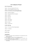
KR AMER ELECTRON ICS LT D.
USER MANUAL
MODEL:
FC-5
Protocol Translator
P/N: 2900-000148 Rev 3
Contents
1 Introduction
1 2 2.1 Getting Started
Achieving the Best Performance
2 2 3 Overview
3 4 Your FC-5 Protocol Translator
4 5 5.1 5.2 5.3 5.4 5.5 Configuring the Kramer FC-5 Manager Software
Installing and Running the Kramer FC-5 Manager Software
Using the Translation List Window
Connecting a PC (CONFIG Port)
Setting the DIP-Switches
Assigning the Translation List Driver Commands
6 6 7 11 12 13 6 6.1 6.2 6.3 6.4 Using the FC-5
Transmitting Commands via a PC or Remote Controller
Transmitting Commands via the Contact closure
Transmitting Commands via the Relays
Transmitting Commands via the Contact closure and Relays
14 14 15 16 17 7 7.1 7.2 7.3 Upgrading the FC-5 Firmware
Downloading from the Internet
Connecting the PC to the RS-232 CONFIG Port
Upgrading Firmware
18 18 18 19 8 Technical Specifications
20 Figures
Figure 1: FC-5 Protocol Translator
Figure 2: FC-5 Underside
Figure 3: Port Selection Window
Figure 4: Translation List Window
Figure 5: New/Open File Menu Command Dialog Box
Figure 6: New Command Window
Figure 7: Edit Command Window
Figure 8: Remove Command Prompt
Figure 9: Connecting a PC
Figure 10: Crossed Cable RS-232 Connection
Figure 11: Straight Cable RS-232 Connection with a Null Modem Adapter
Figure 12: Translation Set DIP-Switches
Figure 13: Transmitting Commands via a PC or Remote Controller
Figure 14: Transmitting Commands via the Contact closure
Figure 15: Transmitting Commands via the Relays
Figure 16: Relay Pinout
Figure 17: Transmitting Commands via the Contact closure and Relays
Figure 18: The JTG Sender Window
4 5 6 7 8 8 9 10 11 11 12 12 14 15 16 16 17 19 FC-5 – Contents
i
1
Introduction
Welcome to Kramer Electronics! Since 1981, Kramer Electronics has been
providing a world of unique, creative, and affordable solutions to the vast range of
problems that confront the video, audio, presentation, and broadcasting
professional on a daily basis. In recent years, we have redesigned and upgraded
most of our line, making the best even better!
Our 1,000-plus different models now appear in 11 groups that are clearly defined
by function: GROUP 1: Distribution Amplifiers; GROUP 2: Switchers and Matrix
Switchers; GROUP 3: Control Systems; GROUP 4: Format/Standards Converters;
GROUP 5: Range Extenders and Repeaters; GROUP 6: Specialty AV Products;
GROUP 7: Scan Converters and Scalers; GROUP 8: Cables and Connectors;
GROUP 9: Room Connectivity; GROUP 10: Accessories and Rack Adapters and
GROUP 11: Sierra Products.
Congratulations on purchasing your Kramer FC-5 Protocol Translator, which is
ideal for the following typical applications:
•
Operating switchers with different RS-232 protocols
•
Controlling screens, projectors, lights, security gates via the relays
•
Using contact closure switches to operate RS-232 controlled equipment
FC-5 - Introduction
1
2
Getting Started
We recommend that you:
•
Unpack the equipment carefully and save the original box and packaging
materials for possible future shipment
•
Review the contents of this user manual
Use Kramer high performance high resolution cables
i
!
2.1
Go to http://www.kramerelectronics.com to check for up-to-date
user manuals, application programs, and to check if firmware
upgrades are available (where appropriate).
Caution:
No operator serviceable parts inside the unit
Warning:
Use only the Kramer Electronics input power wall
adapter that is provided with the unit
Warning:
Disconnect the power and unplug the unit from the
wall before installing
Achieving the Best Performance
To achieve the best performance:
•
Use only good quality connection cables to avoid interference, deterioration
in signal quality due to poor matching, and elevated noise levels (often
associated with low quality cables)
•
Avoid interference from neighboring electrical appliances that may adversely
influence signal quality
•
2
Position your Kramer FC-5 away from moisture, excessive sunlight and dust
FC-5 - Getting Started
3
Overview
The FC-5 is a protocol translator designed to make an RS-232 controlled machine
(Kramer and non-Kramer products) compatible with other RS-232 based protocols.
By default the unit comes configured with two translation drivers, includes a PC
based software program for user configuration, and has two relays and eleven
contact closure control connections.
In particular, the FC-5:
•
By default, comes configured with two translation drivers: a Generic Switcher
Protocol to Kramer’s “Protocol 2000”; and the Sierra Video Systems (SVS)
Protocol to Kramer’s “Protocol 2000”
•
Can also be used as a programmable controller. It features two relays for the
simplified and centralized control of room functions (such as lighting, closing
blinds, and so on). The two output relays have normally open (NO) and
normally closed (NC) contacts
•
Features connections for up to eleven remote contact closure switches (to
trigger RS-232 commands and/or control the relays)
•
Includes an easy-to-use PC application program that lets you build
translation tables for the FC-5 to define the association between codes for
the COM ports, relays and contact closures. The FC-5 can be configured to
work with up to four translation tables, and each one can include up to 256
translation commands. DIP-switches are used to select between the
translation tables
•
FC-5 - Overview
Supports firmware upgrade
3
4
Your FC-5 Protocol Translator
Figure 1 defines the FC-5:
Figure 1: FC-5 Protocol Translator
#
Feature
Function
1
INPUTS Contact Closure Remote
Control PINs
Connects to a contact closure switch (see
Section 6.2
2
RELAY 1 Terminal Block
3
RELAY 2 Terminal Block
Connect to room items (such as lighting,
screen settings, blinds, and so on). The
PINOUT is: NO: Normally Open; C: Common
Voltage; NC: Normally Closed
4
SETUP DIP-switches
Used to select translation drivers (see Section
5.2)
5
12V DC
+12V DC connector for powering the unit
6
COM1 9-pin D-type RS-232 port
Connects to the Kramer or other device
7
COM2 9-pin D-type RS-232 port
Connects to the Kramer or other device
8
CONFIG 9-pin D-type port
Connects to the RS-232 port on a PC
9
STATUS LED
Blinks when transmitting commands
10
ON LED
Illuminates when receiving power
Figure 2 defines the underside switches (with the label removed), which are
designed to be used for firmware upgrade only. An adhesive label (Marked “For
Programming only! Do not remove”) protects access to them. Remove the label
only when upgrading to new firmware (see Section 7).
4
FC-5 - Your FC-5 Protocol Translator
Figure 2: FC-5 Underside
#
Feature
Function
1
Switch
2
Switch
3
Switch
Slide all 3 switches down to set to OFF
(Normal mode, default). Slide all 3 switches
up to set to ON (Program mode)
FC-5 - Your FC-5 Protocol Translator
5
5
Configuring the Kramer FC-5 Manager
Software
This section describes how to:
•
Install and run the Kramer FC-5 Manager software, see Section 5.1
•
Use the Translation List window, see Section 5.2
•
Connect and assign the driver commands to the translation list, see Sections
5.2.1, 5.2.2 and 5.2.3
5.1
Installing and Running the Kramer FC-5 Manager
Software
To install the FC-5 Manager software:
1. Insert the CD-ROM in the CD-ROM drive; double click the FC-5 Manager icon.
The Port selection window appears:
Figure 3: Port Selection Window
2. Choose the appropriate COM port for configuration via the serial cable and
click OK.
The Translation List window (see Figure 4) opens.
6
FC-5 - Configuring the Kramer FC-5 Manager Software
5.2
Using the Translation List Window
Figure 4 defines the Translation List window. Double clicking COMMAND(1) opens
the Edit command window (see Section 5.2.2).
Figure 4: Translation List Window
Feature
Function
File menu
commands
New
Creates a new blank file
Open
Opens or finds a Protocol file (see Figure 5)
Save
Saves the changed command list to the current
translation driver file
Save As
Saves the current file with a different file name or
location
Exits
Closes the application
Restart
Not in use
COM Port
Displays the Port Selection window (see Figure 3)
New Button
Displays the New Command window (see Figure 6)
Edit Button
Displays the Edit Command window (see Figure 7)
Remove Button
Displays the Remove Command prompt (see Figure 8)
Close Button
Closes the Command Translation List window
Assign Button
Transmits the complete set to the COM ports of the FC-5 unit
The data is assigned to the “translation set” according to the DIP-switch
setting at the time that the Assign button is pressed
FC-5 - Configuring the Kramer FC-5 Manager Software
7
Figure 5: New/Open File Menu Command Dialog Box
5.2.1
Entering Data in the New Command Window
Figure 6 defines the New Command window:
Figure 6: New Command Window
8
FC-5 - Configuring the Kramer FC-5 Manager Software
Feature
Function
Properties NAME
Field
Defines the new command NAME
Automatically generates the text: COMMAND (x) where x is the
next number in the sequence. Lets you type over alternative text of
up to 17 characters or leave the field blank
Properties EVENT
Field
Defines the new EVENT. The drop-down list box offers a choice of:
COM1 RECEIVE, COM2 RECEIVE, DRYCONTACT_01 to
DRYCONTACT_11
Properties ACTION
Field
Defines the new ACTION. The drop-down list box offers a choice
of: COM1 TRANSMIT, COM2 TRANSMIT, RELAY_01 ON,
RELAY_02 ON, RELAY_01 OFF, RELAY_02 OFF
Clear Button
Removes the data that is entered in all the text boxes
Add Button
Adds all the data that is entered in the text boxes to that new
command
Close Button
Closes the New Command window
Note: To enter invisible characters in ASCII mode (such as "ENTER") place the
cursor in that square and press the appropriate key on the keyboard.
5.2.2
Editing Data in the Command Window
Figure 7 defines the Edit Command window:
Figure 7: Edit Command Window
FC-5 - Configuring the Kramer FC-5 Manager Software
9
Feature
Function
Properties
NAME Field
Defines the command NAME
Lets you type over alternative text of up to 17 characters or leave the
field blank
Properties
EVENT Field
Defines the new EVENT. Lets you change the selection via the
drop-down list box:
COM1 RECEIVE, COM2 RECEIVE, DRYCONTACT_01 to
DRYCONTACT_11
Properties
ACTION Field
Defines the new ACTION. Lets you change the selection via the
drop-down list box:
COM1 TRANSMIT, COM2 TRANSMIT, RELAY_01 ON, RELAY_02 ON,
RELAY_01 OFF, RELAY_02 OFF
Clear Button
Removes the data that is entered in all the text boxes
Apply Button
Saves any changes made
OK Button
Saves any changes made and closes the Edit Command window
Close Button
Closes the New Command window
Lets you continue to make changes in the Edit Command window
5.2.3
Erasing a Command from the Command Translation List
Window
To erase a command from the Command Translation List window, select the
relevant command and then click Remove. Click Yes to the Remove prompt
message (see Figure 8):
Figure 8: Remove Command Prompt
10
FC-5 - Configuring the Kramer FC-5 Manager Software
5.3
Connecting a PC (CONFIG Port)
This section describes how to connect a PC to the CONFIG port.
Figure 9: Connecting a PC
You can connect to the unit via a crossed RS-232 connection, using for example,
a PC. A crossed cable or null-modem is required as shown in method A and B
respectively. If a shielded cable is used, connect the shield to pin 5.
Method A (Figure 10)—Connect the RS-232 9-pin D-sub port on the unit via a
crossed cable (only pin 2 to pin 3, pin 3 to pin 2, and pin 5 to pin 5 need be
connected) to the RS-232 9-pin D-sub port on the PC.
Note: There is no need to connect any other pins.
9
8
7
6
5
4
3
2
1
9
8
7
6
5
4
3
2
PC
1
Figure 10: Crossed Cable RS-232 Connection
FC-5 - Configuring the Kramer FC-5 Manager Software
11
Hardware flow control is not required for this unit. In the rare case where a
controller requires hardware flow control, short pin 1 to 7 and 8, and pin 4 to 6 on
the controller side.
Method B (Figure 11)—Connect the RS-232 9-pin D-sub port on the unit via a
straight (flat) cable to the null-modem adapter, and connect the null-modem
adapter to the RS-232 9-pin D-sub port on the PC. The straight cable usually
contains all nine wires for a full connection of the D-sub connector. Because the
null-modem adapter (which already includes the flow control jumpering described
in Method A above) only requires pins 2, 3 and 5 to be connected, you are free to
decide whether to connect only these 3 pins or all 9 pins.
9
8
7
6
5
4
3
2
Null-Modem
Adapter
to PC
1
Figure 11: Straight Cable RS-232 Connection with a Null Modem Adapter
5.4
Setting the DIP-Switches
Figure 12 defines the DIP-switches, which are used to select the translation
drivers.
DIPs
Set as follows:
1, 2
Determines the settings of the translation set
3, 4
Reserved
Figure 12: Translation Set DIP-Switches
12
Translation
Set 1
Translation
Set 2
Translation
Set 3
Translation
Set 4
Generic to
Kramer 2000
(default)
Sierra Video Systems
to Kramer 2000
1
OFF
2
OFF
ON
OFF
ON
OFF
ON
ON
FC-5 - Configuring the Kramer FC-5 Manager Software
5.5
Assigning the Translation List Driver Commands
Assign the configured translation list commands driver to the FC-5. The list is
configured to the Translation Set selected by the DIP-switches at the time of the
download. This process can take several minutes. During the process the “Assign”
button of the Kramer FC-5 Manager software application flashes, and the STATUS
LED of the FC-5 unit also flashes. At the end of this process the following
message appears: “Assigned Successfully!”
FC-5 - Configuring the Kramer FC-5 Manager Software
13
6
Using the FC-5
You can use your FC-5 to transmit commands via the:
6.1
•
PC or remote controller, see Section 6.1
•
Contact closure, see Section 6.2
•
Relays, see Section 6.3
•
Contact closure and relays, see Section 6.4
Transmitting Commands via a PC or Remote Controller
You can use your FC-5 to transmit commands via a PC or remote controller:
Figure 13: Transmitting Commands via a PC or Remote Controller
Connect a PC or Remote Controller to the COM1 port and a controlled unit is
connected to the COM2 port. In this example, the PC or Remote Controller
transmits user-defined commands to the Kramer switcher
14
FC-5 - Using the FC-5
6.2
Transmitting Commands via the Contact Closure
You can use the FC-5 to transmit commands via the contact closure (see also
Section 6.4):
Figure 14: Transmitting Commands via the Contact closure
The INPUTS contact closure remote control pins let you temporarily route an input
to the output by momentarily attaching an input to the GND (Ground) pin (do not
connect more than one PIN to the Ground PIN at the same time). In this example
INPUT 3 is routed to the output, by temporarily attaching PIN 3 to PIN GND, and a
Kramer switcher is connected to the COM2 port
FC-5 - Using the FC-5
15
6.3
Transmitting Commands via the Relays
You can use your FC-5 to transmit commands via the relays:
Figure 15: Transmitting Commands via the Relays
A PC or Remote Controller is connected to the COM1 port. Relay 1 is connected
to the blinds, and relay 2 is connected to the lighting system. On each 3-pole
terminal block connector, connect either: C to NO, or C to NC
Figure 16: Relay Pinout
16
C
Common
NO
Normally Open (that is, the electricity is switched ON)
NC
Normally Closed (that is, the electricity is switched OFF)
FC-5 - Using the FC-5
6.4
Transmitting Commands via the Contact Closure and
Relays
You can use your FC-5 to transmit commands via the contact closure to the
relays, and to a projector via RS-232:
Figure 17: Transmitting Commands via the Contact closure and Relays
The INPUTS contact closure remote control pins let you switch commands to the relays,
and via RS-232. Relay 1 is connected to the blinds, and relay 2 is connected to the
lighting system (see Section 6.3 for the Relay PINOUT). INPUT contact closure remote
control pins 1 to 4 are connected to switches 1 to 4, respectively.
In this particular example, pressing:
•
Switch button 1 turns on the projector
•
Switch button 2 turns off the projector
•
Switch button 3 toggles the blinds up/down
•
Switch button 4 toggles the lights on/off
FC-5 - Using the FC-5
17
7
Upgrading the FC-5 Firmware
The FC-5 firmware is located in FLASH memory, which lets you upgrade to the
latest Kramer firmware version in minutes! The process involves:
7.1
•
Downloading from the Internet (see Section 7.1)
•
Connecting the PC to the RS-232 CONFIG port (see Section 7.2)
•
Upgrading Firmware (see Section 7.3)
Downloading from the Internet
You can download the up-to-date file from the Internet. To do so:
The files indicated in this section are given as an example only. The actual file names can be
modified
1. Go to our Web site at http://www.kramerelectronics.com and download the
file: “JTG_FC-5.zip” from the Technical Support section.
2. Extract the file: “JTG_FC-5.zip” to a folder (for example, C:\Program
Files\Kramer Flash).
3. Install the JTG-Sender application.
7.2
Connecting the PC to the RS-232 CONFIG Port
Before installing the latest Kramer firmware version on an FC-5, do the following:
1. On the underside (see Figure 12), slide all three switches to ON (Program
Mode), using a screwdriver.
2. Connect the 12V DC power adapter to the power socket and connect the
adapter to the mains electricity.
3. Open the JTG-Sender application (see Section 7.1).
4. Connect the RS-232 9-pin D-type CONFIG port to the null-modem adapter
and connect the null-modem adapter with a 9-wire flat cable to the RS-232
9-pin D-type COM port on your PC (see Section 5.3).
18
FC-5 - Upgrading the FC-5 Firmware
5. Follow the steps outlined in Section 7.3.
7.3
Upgrading Firmware
Follow these steps to upgrade the firmware:
1. Double click the JTG-Sender desktop icon.
The JTG-Sender window appears (see Figure 18).
Figure 18: The JTG Sender Window
2. Select the required COM Port (to which the Remote Control is connected on
your PC ).
3. Press the File button to select the .jtg firmware file included in the package.
4. Click the Send button to download the file. The Send button lights green.
5. Wait until downloading is completed and the green Send button turns off.
6. Disconnect the 12V DC power.
7. On the underside (see Figure 12), slide all three switches to OFF (Normal
Mode), using a screwdriver.
8. Connect the 12V DC power adapter to the power socket and connect the
adapter to the mains electricity.
The FC-5 now functions with the upgraded firmware.
FC-5 - Upgrading the FC-5 Firmware
19
8
Technical Specifications
INTERFACE:
RS-232 9-pin D-sub connectors (COM1, COM2, and CONFIG);
contact closure remote control PINS on terminal block
connectors; 2 x 3-pole RELAY on terminal block connectors
(36V AC or DC, 2A, 60V AC maximum on non-inductive load)
CONTROL:
LEDs: STATUS and ON
POWER SOURCE:
12V DC, 60mA
DIMENSIONS:
12cm x 7.15cm x 2.76cm (4.7” x 2.8” x 1.08”) W, D, H
WEIGHT:
0.3kg (0.67lbs) approx
ACCESSORIES:
Power supply, mounting bracket, Kramer's Windows®-based
configuration software, null modem connector
OPTIONS:
RK-3T 19" rack adapter
Specifications are subject to change without notice at http://www.kramerelectronics.com
20
FC-5 - Technical Specifications
LIMITED WARRANTY
We warrant this product free from defects in material and workmanship under the following terms.
HOW LONG IS THE WARRANTY
Labor and parts are warranted for seven years from the date of the first customer purchase.
WHO IS PROTECTED?
Only the first purchase customer may enforce this warranty.
WHAT IS COVERED AND WHAT IS NOT COVERED
Except as below, this warranty covers all defects in material or workmanship in this product. The following are not
covered by the warranty:
1. Any product which is not distributed by us or which is not purchased from an authorized Kramer dealer. If you are
uncertain as to whether a dealer is authorized, please contact Kramer at one of the agents listed in the Web site
www.kramerelectronics.com.
2. Any product, on which the serial number has been defaced, modified or removed, or on which the WARRANTY VOID
IF TAMPERED sticker has been torn, reattached, removed or otherwise interfered with.
3. Damage, deterioration or malfunction resulting from:
i) Accident, misuse, abuse, neglect, fire, water, lightning or other acts of nature
ii) Product modification, or failure to follow instructions supplied with the product
iii) Repair or attempted repair by anyone not authorized by Kramer
iv) Any shipment of the product (claims must be presented to the carrier)
v) Removal or installation of the product
vi) Any other cause, which does not relate to a product defect
vii) Cartons, equipment enclosures, cables or accessories used in conjunction with the product
WHAT WE WILL PAY FOR AND WHAT WE WILL NOT PAY FOR
We will pay labor and material expenses for covered items. We will not pay for the following:
1. Removal or installations charges.
2. Costs of initial technical adjustments (set-up), including adjustment of user controls or programming. These costs are
the responsibility of the Kramer dealer from whom the product was purchased.
3. Shipping charges.
HOW YOU CAN GET WARRANTY SERVICE
1. To obtain service on you product, you must take or ship it prepaid to any authorized Kramer service center.
2. Whenever warranty service is required, the original dated invoice (or a copy) must be presented as proof of
warranty coverage, and should be included in any shipment of the product. Please also include in any mailing a
contact name, company, address, and a description of the problem(s).
3. For the name of the nearest Kramer authorized service center, consult your authorized dealer.
LIMITATION OF IMPLIED WARRANTIES
All implied warranties, including warranties of merchantability and fitness for a particular purpose, are limited in duration
to the length of this warranty.
EXCLUSION OF DAMAGES
The liability of Kramer for any effective products is limited to the repair or replacement of the product at our option. Kramer
shall not be liable for:
1. Damage to other property caused by defects in this product, damages based upon inconvenience, loss of use of the
product, loss of time, commercial loss; or:
2. Any other damages, whether incidental, consequential or otherwise. Some countries may not allow limitations on
how long an implied warranty lasts and/or do not allow the exclusion or limitation of incidental or consequential
damages, so the above limitations and exclusions may not apply to you.
This warranty gives you specific legal rights, and you may also have other rights, which vary from place to place.
NOTE : All products returned to Kramer for service must have prior approval. This may be obtained from your dealer.
This equipment has been tested to determine compliance with the requirements of:
EN-50081:
EN-50082:
CFR-47:
"Electromagnetic compatibility (EMC);
generic emission standard.
Part 1: Residential, commercial and light industry"
"Electromagnetic compatibility (EMC) generic immunity standard.
Part 1: Residential, commercial and light industry environment".
FCC* Rules and Regulations:
Part 15: “Radio frequency devices
Subpart B Unintentional radiators”
CAUTION!
Servicing the machines can only be done by an authorized Kramer technician. Any user who makes changes or
modifications to the unit without the expressed approval of the manufacturer will void user authority to operate the
equipment.
Use the supplied DC power supply to feed power to the machine.
Please use recommended interconnection cables to connect the machine to other components.
* FCC and CE approved using STP cable (for twisted pair products)
FC-5 - Technical Specifications
21
For the latest information on our products and a list of Kramer distributors,
visit our Web site where updates to this user manual may be found.
We welcome your questions, comments, and feedback.
Web site: www.kramerelectronics.com
E-mail: [email protected]
!
SAFETY WARNING
Disconnect the unit from the power
supply before opening and servicing