1
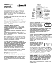
MR64 Keypad Installation Instructions Congratulations and thank you for choosing this Knoll product. The MR64 keypads are the power behind an advanced music control system that is easy-to-use with top quality sound available in up to six or more rooms. The MR64 is only for use with the MVP44a, MVP64a and MR640 controller. MR64’s can be used in combination with MR60 keypads in the same system, but only one keypad per zone is permitted. Please see the manuals shipped with the MVP44a, MVP64a or MR600. The MR64 is available with two LCD colors, yellow-green with black lettering and blue with white lettering (model MR64b). Both versions are available with Decora™ style bezel plates in white, almond, black or ivory colors. The music system consists of: 1. Rooms with stereo speakers, a MR64 or MR60 keypad or infrared receiver and a remote control. 2. One or more MVP44a, MVP64a or MR640 controller(s). 3. One or more multi-zone amplifiers if the MR640 is used. 4. Stereo source components such as tuners, CD players, satellite dish receivers, cassette decks, and other components. While the MR64 evolved after years of research, its use is straightforward and direct. Some rooms may have more than one pair of speakers but only one keypad or possibly even no keypad. The music system is controlled by the MR64 and MR60 keypads, RB8 or universal remote, the source components and possibly a whole home controller. The source components are controlled by their individual remote controls by aiming the remote control at the keypad or infrared receiver and pressing the appropriate remote control button. MR64 keypad installation Individual rooms can be controlled by a MR64, MR60 and/or an RB8 remote control or a universal remote control with the RB8 commands installed. MR60 and MR64 keypads control the speakers for the room it is located in or the whole house (all rooms). The RB8 remote can turn off the whole house but can only turn on and adjust the room it is in. Setting the dipswitch Before installing any MR64 keypad, the dipswitch on the rear of the keypad has to be set. The dipswitch will have one of the three switches set to on and the other two off. This feature was added so that in non-new or existing construction, three keypads for three rooms can be connected to one cat 5 wire. MR64 dipswitch settings for speaker outputs A1 and B1 1 2 3 ON OFF MR64 dipswitch settings for speaker outputs A2 and B2 1 2 3 ON OFF MR64 dipswitch settings for speaker outputs A3 and B3 1 2 3 ON OFF The dipswitch has to be set even if the wires are home run to the controller. The dipswitch 1 is set to ON (dipswitch 2 and 3 are set to OFF) if this keypad is to control amp A1 or B1 and the speakers in this room are connected to A1 or B1. If this keypad is to control amplifier B1 then the cat 5 wire from this keypad can be connected to slot B1, B2 or B3. Similarly if the next keypad is to control amp A2 or B2 the dipswitch 2 is set to ON (dipswitch 1 and 3 are set to OFF) and the speakers in this room are connected to A2 or B2. If this keypad is to control amplifier A2 then the cat 5 wire from this keypad can be connected to slot A1, A2 or A3 If two or three keypads are connected to the controller by one cat 5 wire the two or three keypads need to have dipswitches set to different settings and the two or three zones have to be in the same controller bank of A or B. The single wire can then be plugged into one of the three slots on that bank (example for bank B, slot B1, B2 or B3). Please note the MVP44a does not have slot or output for A1 or A2. Keypad Wiring The MR64 requires a single cat 5 wire. Up to three rooms each with a single MR64 or MR60 keypad can be run on a single cat 5 wire. Two to three rooms of keypads are normally run on a single cat 5 wire if installing in existing construction or if one cat 5 wire has been damaged after installation. In new construction it is best to run a single home run wire from the MR64 or MR60 keypad location back to the controller or controller amplifier. Cat 5 wires for this system need to be terminated with the correct RJ45 connector. RJ45 connectors are designed specifically for solid, stranded or special wires, so be sure to obtain the correct type. Please use a good quality crimper for this purpose. Use the standard cat 5 wire practices including the correct wire order (see the controller manual for the diagram). Note: If after installation the keypads are not working properly, or controlling another zone or not working at all, carefully check the MR64 dipswitch settings, wiring order on the RJ45 connections, wiring layout and even try recrimping the connectors or replacing the RJ45 connectors with new ones. Verify that the wires are connected to the correct bank on the rear of the controller (A or B). The most common installation problem with this whole system is poorly crimped or wires in the wrong order on the RJ45. Please use a good quality crimper and a cat 5 wire tester to verify the connections. Note: In addition to the cat 5 wires to the keypads, two pairs of speaker wire need to be run from the amplifier to the speakers (one pair to each speaker). These wires do not have to run to the keypad location but can be run directly to the speakers. We suggest a minimum 16-gauge wire and 12-14 gauge if the runs are longer than 33 feet (10 meters). Programming MR64 Labels After the dipswitch is set and the MR64 is installed in the wall the four source identification labels have to be programmed individually into each MR64. There are over 25 labels available and custom labels are available for a nominal charge (maximum 8 characters). Labels can be programmed from the MR64 keypad only when it is powered up and not from the remote control. Each MR64 keypad must be programmed individually and it will save the label names even if the keypad is disconnected from the systems. MR64 keypad labels can be programmed offsite if desired. Note: All of the MR64 keypads in this system have to be programmed with the same labels in the same source order. First make sure all of the wires from the MR64(s) to the controller are installed and tested (if possible) properly with crimped RJ45 connectors. The wires from the amp to the speaker do not have to be installed at this time but it is preferred if they are. The sources should be connected, but again, it is not necessary to have the source wires connected to program the MR64 labels. Using the back of this manual, please write down the source name connected to source A, source B, source C and source D. Turn the MVP44a, MVP64a on using the power button on the front panel or the MR640 by connecting the power supply. As soon as the power is turned on the MR64 will first show which software revision it is programmed with, display “Knoll Systems” and then display “System Off”. Labels can only be programmed or changed by entering the MR64 installer menu when the LCD displays “System Off”. All of the available labels are the same for all four sources. To enter the installer menu from “System Off” press the MR64 keypad (not remote) MUTE button for about 1 second then immediately press the INPUT for about 5 seconds. Release the INPUT button as soon as the LCD displays SET A Source A Now press the UP or DOWN buttons next to the INPUT buttons to scroll through the label selections for source A on the bottom row of the LCD display. When the correct selection is displayed press the MUTE button to confirm this choice. Note: If a mistake is made, go though the rest of the programming setup and restart the installer mode again. The LCD display then displays SET B Source B As above press the UP or DOWN buttons next to the INPUT buttons to scroll through the label selections for source B on the bottom row of the LCD display. When the correct selection is displayed press the MUTE button to confirm this choice. The LCD display then displays SET C Source C As above press the UP or DOWN buttons next to the INPUT buttons to scroll through the label selections for source C on the bottom row of the LCD display. When the correct selection is displayed press the MUTE button to confirm this choice. The LCD display then displays SET D Source D As above press the UP or DOWN buttons next to the INPUT buttons to scroll through the label selections for source D on the bottom row of the LCD display. When the correct selection is displayed press the MUTE button to confirm this choice. The LCD display then displays System Off And the MR64 labels have been set. To change any of the labels you can re-enter the installer menu and scroll through all four labels and reset the ones needed. MR64 LCD display Input select button Volume select button Mute button Line 1 Line 2 Volume up and down or source select or sets backlighting INPUT All button for whole house functions VOL ALL MUTE Shut off this room or shut off whole house (press for 5 seconds). OFF Infrared receiver RB8 Remote Control Functions Power: switches room off or whole house off(press for 5 seconds) Input 1-4: Turns on room and selects input music source MUTE POWER 1 2 3 4 + INPUT VOL systems RB8 - Mute: Mutes music. to restore, press mute, input 1-4 or volume up/down Volume Up/Down Press and hold for continuous volume changes Source Labels As of version 3.3 the source labels are: CD, CD2, FM, AM, SAT, SAT2, AUX, AUX2, MP3, TV, DVD, DVD2, PC, DEC, MC-PC, MCEx, JAZZ, POP, COUNTRY, NEWS, CLASSIC, HIPHOP, ROCK, CONTEMP, RAP, SPORTS, TALK, IPOD Source A ______________________________ Source B_______________________________ Source C ______________________________ Source D_______________________________ Date of Installation ______________________ 2002-2005 Knoll Systems. All rights reserved v1.0