1
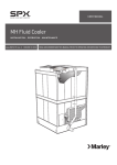
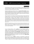
SIRIUS II
2, 4 & 8 ZONE
CONVENTIONAL
FIRE ALARM CONTROL PANEL
INSTALLATION,
OPERATION AND
MAINTENANCE MANUAL
TM0110
PROPRIETARY RIGHTS NOTICE
The information contained in this manual is the property of Kidde Products Limited and may not be
reproduced or transmitted in any form or by any means, electronic, mechanical, photocopying, recording or
otherwise, nor stored in any retrieval system of any nature without the express written authority of
Kidde Products Limited.
Kidde Fire Protection is a trading brand of Kidde Products Limited
© Copyright 2007 Kidde Products Limited
TM0110
Page 1 of 22
Issue 1.00
TABLE OF CONTENTS
Chapter
1.0
2.0
3.0
4.0
5.0
Page
Description
1.1
General Description
1.2
Display Panel
1.3
Indicators
1.4
Controls
1.5
EN54 Optional Functions With Requirements
1.6
Ancillary Functions Not Required By EN54
1.7
Internal Links
3
4
4
5
7
7
7
Operation
2.1
General
2.2
Time / Date
2.3
Day / Night Mode
2.4
Disablements
2.5
View
8
8
8
9
9
Installation and Commissioning
3.1
General
3.2
Installation
3.3
Circuit Connection Details
3.4
Commissioning
10
11
12
15
Maintenance
4.1
General
4.2
Routine Maintenance
19
19
Specifications and Data
5.1
Wiring Specification
5.2
Approved Detector Types
5.3
Technical Specifications
5.4
Battery Replacement
20
20
20
22
LIST OF FIGURES
Figure 1
Figure 2
Figure 3
Figure 4
Figure 5
8 Zone Sirius II Fire Alarm Panel
Sirius II Display Panel
Access Level 2 Menu Structure
External Connections
Electrical Connections With Battery
3
4
9
14
15
Access Levels
Internal Links
5
7
LIST OF TABLES
Table 1
Table 2
TM0110
Page 2 of 22
Issue 1.00
CHAPTER 1
DESCRIPTION
1.1
GENERAL DESCRIPTION
Sirius II is a conventional fire alarm control panel designed to EN54 Parts 2 & 4. The Sirius II range
comprises 2, 4 and 8 zone versions. An 8 zone panel is shown in Figure 1.
The panel is housed in a metal enclosure and contains a main motherboard which is provided with a
DC supply from a power supply unit (PSU). The PSU is powered from AC mains and two 12 V, 7 Ah
lead acid batteries (wired in series) are used for the secondary supply source if the mains supply fails.
Each zone provided by the panel is monitored for faults. The panel provides two standard
conventional alarm circuits.
The display panel provides the visual indications and user controls.
Figure 1: 8 Zone Sirius II Fire Alarm Panel
TM0110
Page 3 of 22
Issue 1.00
1.2
DISPLAY PANEL
All indications and controls are available via the Sirius II display panel (Figure 2). This incorporates a
two line by 16 character liquid crystal display with back light and this indicates panel fire and fault
conditions and user and engineer menus when accessed.
Figure 2: Sirius II Display Panel
1.3
INDICATORS
The following indicators are provided on the panel display:
POWER ON
The green POWER ON light comes on if primary power (AC mains) or
secondary power (batteries) provide power to the panel.
POWER FAULT
The yellow POWER FAULT light flashes 1 second on 1 second off if a
fault occurs with the panel internal mains or battery power supply.
SYSTEM FAULT
The yellow SYSTEM FAULT light comes on if the panel has a system fault
condition (software or hardware).
GENERAL FAULT
The yellow COMMON FAULT light flashes 1 second on 1 second off if any
panel fault condition occurs.
SOUNDER STATUS
The yellow SOUNDER STATUS light flashes 1 second on 1 second off if
an alarm circuit fault occurs. If the alarm circuits have been disabled, this
light will be steady on.
FIRE OUTPUT STATUS
The yellow FIRE OUTPUT STATUS light flashes 1 second on 1 second
off if a fault occurs on the fire output or will be steady on if the fire output
is disabled.
OUTPUT DELAYS
The yellow OUTPUT DELAYS light flashes 1 second on 1 second off
when panel alarm circuits and fire outputs are active but delayed in
operation, remains steady when output delays are enabled and goes off if
delays are disabled.
TM0110
Page 4 of 22
Issue 1.00
FIRE ALARM
The red FIRE ALARM light comes on when any zone is in a fire alarm
condition. This light flashes 1 second on 1 second off when a new zone
fire alarm event occurs and is constant when accepted by operation of the
silence/resound sounders switch. Operation of the panel reset switch
turns this light off only if the alarm condition is removed.
FIRE OUTPUT
The red FIRE OUTPUT light comes on when the monitored and non
monitored fire outputs are active.
GENERAL DISABLE
The yellow GENERAL DISABLE light comes on if any zone monitoring
circuit, alarm circuit, fire output or output delays are disabled.
GENERAL TEST
The yellow GENERAL TEST light comes on if the panel has one or more
zones in test mode.
MORE MESSAGES
The yellow MORE MESSAGES light comes on if there are more than 2
messages available on the display.
ZONE FIRE
The red ZONE fire light comes on if there is a fire on a specific zone.
ZONE FAULT
The yellow ZONE fault light flashes 1 second on 1 second off on a zone
fault condition, flashes 0.5 second on, 0.5 second off if a zone is in test or
is steady on if a zone is disabled.
PANEL ACCESS
The yellow PANEL ACCESS light comes on if the panel is in access level
2 and flashes 1 second on 1 second of when the panel is in access level
3.
1.4
CONTROLS
The four access levels to the panel’s controls are shown in Table 1.
Access Level
Operating Level
PANEL ACCESS Light
Time Out
Pass Code
1
Normal operation
Off
N/A
N/A
2
User
On constantly
N/A
7179
3
Engineer
Flashing (1 second on/off)
30 seconds
7134
4
Engineer (counter clear)
Flashing (1 second on/off)
N/A
N/A
Table 1: Access Levels
Access Level 1 is the normal operating condition, where, with no zones disabled, the green POWER
ON light is on and all other lights are off. The TEST button, which is used to test all of the lights in the
panel display, is operative. The SILENCE BUZZER button is active, but only for faults and not for
alarm conditions. All other controls are inoperative and are only available in Access Level 2.
The panel control switches sound the panel internal buzzer when operated. If any of these switches
are operated for more than 10 seconds or are stuck in the on position, the panel indicates a fault
condition, SYSTEM FAULT light flashes 1 second on 1 second off, the internal panel buzzer sounds
intermittently and the fault output is active.
TM0110
Page 5 of 22
Issue 1.00
The following controls are available in Access Level 2:
SILENCE / RESOUND
ALARMS
If the panel has a zone fire state, operation of the SILENCE / RESOUND
ALARMS switch silences all alarm devices, ALARM and ZONE fire lights
stop flashing and stay on constantly and the buzzer sounds intermittently. If
a new zone alarm condition occurs, the fire state conditions are re-enabled.
Repeat operations of the switch toggles the panel between re-sounding and
silencing of the external alarms and the panel buzzer.
RESET
If the panel has standing faults on the display, operation of the RESET
switch clears these faults. If the panel has any standing alarm conditions,
the SILENCE RESOUND ALARMS switch MUST be operated first to enable
the RESET switch. System reset forces the panel into a quiescent state. If
standing panel alarms or faults remain, after a short delay they will be reenabled.
NOTE: After operation of the RESET switch the panel has a delay of
about 5 seconds before any other switch can be activated (except test
lamps).
SILENCE BUZZER
If there is an alarm, panel access must be enabled for operation of this
switch. If the panel internal buzzer is sounding, operation of the SILENCE
BUZZER switch silences the panel buzzer. Any new event resounds the
buzzer and operation of the switch is again required to silence it.
SCROLL
Operation of the SCROLL switch when more than 2 panel events are active,
updates line 1 of the display with the next event in the queue. Line 1 reverts
back to the first panel event if this switch is not pressed within 10 seconds.
TEST
This switch is always active. Operation of the switch makes all display lights
come on and also sounds the panel buzzer continuously.
MENU
Operation of the MENU switch allows the user to select panel operator
functions and engineer functions. To enable panel engineer functions the
user must initially enter the 4 digit engineer code (refer to Table 1).
ENTER
The ENTER switch is used to accept user and engineer function
configuration changes.
ACCESS
The ACCESS switch allows the operator to input the 4 digit code to allow
panel access. When the panel is accessed the PANEL ACCESS light
comes on, all key switches are enabled and operator access functions can
be selected.
PANEL EDITING
SWITCHES
When the operator selects an access function or engineer function, several
operator switches can be used for editing:
• The MORE MESSAGES switch is also used for switch 1 and switch UP.
• The TEST DISPLAY switch is also used for switch 2 and switch DOWN.
• The MENU switch is also used for switch 3 and switch LEFT.
• The ENTER switch is also used for switch 4 and switch RIGHT.
• The ACCESS switch is also used for switch 5 and switch EXIT.
TM0110
Page 6 of 22
Issue 1.00
1.5
EN 54 OPTIONAL FUNCTIONS WITH REQUIREMENTS
The panel has the following optional functions:
• Output to fire alarm devices.
• Output to fire alarm routing equipment.
• Delays to outputs.
• Coincidence detection.
• Alarm counter.
• Test condition.
• Two sounder circuits.
1.6
ANCILLARY FUNCTIONS NOT REQUIRED BY EN54
• Auxiliary change over contacts:
-One change over contact operating on any fire condition.
-One change over contact operating on any fault condition.
• One auxiliary power supply output.
• One monitored remote input for sounder circuit test.
• Total loss of the power supply.
1.7
INTERNAL LINKS
The internal links are shown in Table 2.
Link Ref.
Function
Option
LK1
Earth fault monitoring.
With the link made, the panel provides monitoring
for earth faults on external wiring.
LK2
Disable internal buzzer.
Removing the link disables the internal buzzer.
LK3
Repeater end of line resistor.
The link should be made if the panel is to be
connected to repeaters. The link is not fitted on 2
zone panels.
LK4
Option cards end of line resistor.
The link should be made if any of the option cards
are to be installed in the panel. The link is not
fitted on 2 zone panels.
CN3
Alarm counter clear
Temporarily making this link clears the alarm
counter to zero.
Table 2: Internal Links
TM0110
Page 7 of 22
Issue 1.00
CHAPTER 2
OPERATION
2.1
GENERAL
Under normal operating conditions, the green POWER ON light is on and the zone window lights are
off.
When a fire condition is detected, the applicable red zone fire light flashes, the red ALARM light
flashes, the red FIRE OUTPUT light comes on, the alarm sounder circuits are activated (unless
programmed off) and the buzzer on the panel sounds continuously.
If a fire indication shows in one or more zones and after the appropriate fire drill has been completed,
to silence the alarms:
• enter Level 2 (the yellow ACCESS light comes on).
• operate the SILENCE RESOUND ALARMS switch (the audible buzzer sounds intermittently, the
• zone light, the FIRE OUTPUT light and the ALARM light stay on. The audible alarm circuits go off
and the fire output circuit remains active.)
When all zone fire conditions have been rectified, operate the SYSTEM RESET switch, (the panel
reverts to Level 1). If the fire condition still exists, the panel reverts to the alarm condition. To reset
the panel it may be necessary to clear smoke or heat from the detectors and to replace the glass in
the manual fire call point.
If a fault occurs, the applicable yellow zone fault light flashes, the applicable yellow SYSTEM FAULT,
COMMON FAULT or SOUNDER FAULT light flashes and the buzzer on the panel sounds
intermittently (one second on, three seconds off).
When in Access Level 2, all other panel operator functions can be accessed when the MENU and
then UP or DOWN switches are operated, ie:
•
•
•
•
TIME / DATE
DAY / NIGHT MODE
DISABLEMENTS
VIEW
2.2
TIME / DATE
This function allows the operator to enter a new date and time. In panel quiescent condition the day
and time are displayed on line 1 of the display. When a panel zone alarm condition occurs, the time
is displayed with the zone in alarm message. Panel Night to Day delay mode of operation relies on
the time for switch-over. To exit the time/date function at any time press the EXIT switch, or do not
operate any switch for 30 seconds.
2.3
DAY / NIGHT MODE
This function allows the operator to turn the Day / Night panel mode of operation (see page 18) on or
off. When enabled, this delays the operation of the panel alarms and fire outputs when zone fire
alarm events occur in the day. If enabled the OUTPUT DELAYS light is on.
TM0110
Page 8 of 22
Issue 1.00
2.4
DISABLEMENTS
The disablement function allows the operator to disable several panel functions.
The ZONE DISABLEMENT function allows the user to enable/disable one or more zone monitoring
circuits. If a zone monitoring circuit is disabled, the panel ignores that zone’s fire, short circuit fault,
open circuit fault or head removed fault conditions. The disabled zone does not affect any of the
other zone monitoring circuits. In the quiescent state, a disabled zone is indicated by the ZONE fault
light on and the GENERAL DISABLE light on.
The ALARM DISABLEMENT function allows the user to enable/disable the panel alarm circuits. This
inhibits the panel fire alarm devices from operation when an alarm condition occurs. It also inhibits
the panel from monitoring for an open or short circuit fault condition. In the quiescent state, the alarm
disablement condition is indicated by the SOUNDER STATUS fault light on and the GENERAL
DISABLE light on.
The FIRE DISABLEMENT function allows the user to enable/disable the panel fire output. This
inhibits the fire outputs from operation when any panel zone fire alarm condition occurs. It also
inhibits the panel from monitoring for a fire output open or short circuit fault condition. In the
quiescent state, the fire output disablement condition is indicated by the FIRE OUTPUT STATUS light
on and the GENERAL DISABLE light on.
2.5
VIEW
The view function allows the user to view the total amount of panel alarms registered.
The Access Level 2 menu structure is summarised in Figure 3:
MENU
1: USER FUNCTION
1
TIME/DATE
SEL
UP
VIEW
SEL
ALARM COUNTER
UP
DISABLEMENTS
SEL
ZONE DISABLEMENT
SEL
ALM DISABLEMENT
SEL
UP
2: ENT ENG CODE
2
*ENTER NEW DATE*
DD/MM/YYYY
FIRE DISABLEMENT
SEL
SEL
SEL
SEL
*ALARM COUNTER*
TOTAL ALARMS 0
ZONE 1 ENABLED
AUX ALARMS EN
AUX FIRE EN
DAY/NIGHT MODE
*ENGINEER CODE*
7134 (DEFAULT)
Figure 3: Access Level 2 Menu Structure
NOTE: Access Level 3 options are detailed in Chapter 3 –
Installation & Commissioning.
TM0110
Page 9 of 22
Issue 1.00
CHAPTER 3
INSTALLATION AND COMMISSIONING
3.1
GENERAL
Installation of the fire detection and alarm system must comply with all applicable national and local
regulations, standards and working practices.
Take care not to install cables in the proximity of high voltage cables or in areas likely to induce
electrical interference. Junction boxes should be avoided, but if they have to be installed then they
must clearly be labelled "Fire Alarm". Refer to Figure 4 for the External Wiring Diagram.
It is recommended that screened cables be used throughout the installation. All cables must be
stripped in accordance with the manufacturer's guidelines. They must be secured to the enclosure
using appropriate metal compression glands and metal locking nuts in conjunction with a metal shake
proof washer to ensure that the cable metal sheath is bonded to the enclosure.
The cabling for the detection and sounder circuits is classed as low voltage and should be segregated
from mains voltages. The pre-formed knockouts shown in Figure 5 must be carefully removed, where
required, using a flat broad-bladed screwdriver and hammer. Use of excessive force should not be
required and may damage the enclosure around the knockout. The surrounding paint must be
carefully removed to permit metal to metal contact between the enclosure and cable gland.
The total current supplied by the panel power supply is 2.5A, which is shared by the auxiliary alarm
devices, common fire and fault output devices and auxiliary 28V supply peripherals. Panel load
calculations MUST not exceed 2.5A.
WARNING
The static handling procedures must be adhered to and extreme caution must be exercised
when working inside the control panel due to the presence of mains voltage 230 V AC.
Static Sensitive Devices
A static sensitive device is any transistor or integrated circuit that may be permanently damaged due
to electrostatic potentials and is generally encountered during routine handling, repair and
transportation.
Static electricity is produced almost every time plastics or textiles are stroked or separated. Static
charges are collected on adjacent conductors and are delivered in the form of sparks passing
between conductors through insulating space or material. The perspiration layer on the human skin is
a sufficient medium to store induced static charges and deliver them to any receptive conductor such
as a component or printed circuit board.
All static sensitive devices are marked accordingly, but it is good
engineering practice to treat all components and boards with the
same degree of protection.
TM0110
Page 10 of 22
Issue 1.00
Static discharges can be reduced by following these guidelines:
1. Always use conductive or anti-static containers for transportation and storage.
2. Wear an earth wrist strap while handling, ensuring a good earth connection is maintained.
3. Never subject a static sensitive device to a sliding movement over any surface and avoid any
direct contact with the pins.
4. Avoid placing sensitive devices on plastic or vinyl surfaces.
5. Minimise the handling of sensitive devices and PCBs.
3.2
INSTALLATION
SIRIUS II 2/4/8 conventional control panels are simple to install and commission if the following
precautions are observed. Do not attempt to install or commission the control panel until this manual
has been read and understood. It is assumed that the system, of which the control panel is a part,
has been designed by a competent fire alarm system designer in accordance with EN 54-2:1997 and
EN 54-4:1997 and any other local codes of practice that are applicable. The design drawings should
clearly show the positions of ALL field devices and the control equipment.
CAUTION
FOLLOW ALL INSTRUCTIONS in this manual. These instructions must be
followed to avoid damage to the control panel and associated equipment. Do
not use a high voltage Megger when detector bases and peripherals have been
fitted to the zone wiring.
The panels, like all electronic equipment, may be adversely affected by extreme environmental
conditions. The position chosen for the installation should therefore be clean and dry and not
subjected to high levels of vibration or shock. The ambient temperatures should be in the range of
5ºC to 40ºC and the relative humidity below 95% (non-condensing).
These panels have been designed with electronic protection. Although no system is completely
immune from lightning transients and interference, proper earthing will reduce susceptibility. The use
of overhead or outside aerial wiring is not recommended due to the increased susceptibility to nearby
lightning strikes. The panel must be mounted at least 2 metres away from pager systems.
The panel is normally surface mounted and should be installed within the building to be protected at a
prominent location and at a height where it can be easily accessed during an emergency. The control
panel should ideally be located in the entrance, foyer or hallway of the building at eye level. The panel
should not be positioned where conditions may affect its performance. Areas prone to salt air,
moisture, high humidity, physical abuse, and extreme temperatures should be avoided.
Remove the control panel from its packing and remove the front cover. Hold the panel to the wall at
the desired mounting height and mark the position of the four screws holes. Drill holes to the required
size and depth and secure the panel to the wall using suitable fixings such that adequate support is
provided.
All cables should be screened in accordance with local fire regulations and should be glanded and
brought into the cabinet through the top or bottom apertures provided in the back box assembly.
Leave the protection plugs in any unused holes. Tails should be of sufficient length to connect to the
relevant terminals. Great care should be taken to avoid damage to the PCB. Terminals accept 0.75
mm to 2.50 mm square stranded or solid conductor.
Do not over-tighten screw terminals. Over-tightening may damage threads, resulting in reduced
terminal contact pressure and difficulty with cable removal.
To meet the EMC requirements of the European Directives, it is necessary to ensure that a screened
or metal sheathed cable is used. It is also important to use only metal glands on the cable and to
ensure that the screen or sheath is connected to the gland.
Before connecting the panel or field devices, the field wiring should be tested for insulation and
continuity, earth faults and cross connections faults etc. Connect the end of line capacitor across the
TM0110
Page 11 of 22
Issue 1.00
last device in each of the zone wirings, end of line resistors across auxiliary alarm circuits and fire
outputs. Connect all field devices. Once any field bases or devices are connected, DO NOT USE a
high voltage Megger on the circuitry; low voltage multimeters may be used. Verify using a multimeter
that all zone, auxiliary alarm circuit and fire output end of line capacitors and resistors can be seen. If
a zone, auxiliary alarm circuit or the fire output is not used, then the appropriate end of line capacitor
or resistor MUST be fitted in the panel field terminals.
3.3
CIRCUIT CONNECTION DETAILS
The panel provides field wiring connections (see Figure 4) whose functions are described below:
AUXILIARY 28V SUPPLY
The panel provides an auxiliary 28V DC supply output rated at 500 mA 28V, which may vary during a
mains failed condition. This output is fused and fuse failure will be indicated as a panel fault. The
panel will monitor this output for excessive current drain or for a ruptured fuse and will indicate a
panel fault if one of the above conditions occurs. This supply allows for external peripherals to be
powered from the panel. The auxiliary supply terminals are labelled AUX 28V, 28V and 0V.
FIRE OUTPUT [FIRE 1]
The panels provide a fire output rated at 500 mA 28V, which may vary during a mains failed condition.
This output is current limited and overload protected by a smart FET circuit. The output is reverse
polarity monitored for open and short circuit fault conditions. This output MUST be terminated with a
6K8 end of line resistor. When active by any zone fire alarm condition, it will provide 28V DC. Fire
output 1 terminals are labelled FIRE 1, + -. This option is not available in the two zone version.
AUXILIARY FIRE OUTPUT [FIRE 2]
CAUTION
This fire output should not be used for any mandatory functions specified by
EN54-2. The volt free relay contacts must not be used to directly switch any
voltage which exceeds 30V DC.
Changeover contacts are provided which operate on any zone fire alarm condition. Fire output 2
terminals are labelled FIRE 2, NO, P, NC.
AUXILIARY FAULT OUTPUT
CAUTION
This fault output should not be used for any mandatory functions specified by
EN54-2. The volt free relay contacts must not be used to directly switch any
voltage which exceeds 30V DC.
Changeover contacts are provided which operate on any panel fault condition. This output is fail-safe
and is active in a system fault, or if the system suffers failure of all power supplies. The fault output Is
labelled FAULT, NO, P, NC.
CLASS CHANGE
The panel provides a monitored class change input which, when active, will operate all panel alarm
devices only. When this input is not active the alarm devices will turn off, providing there are no
standing alarm conditions. To use the input, a normally open switch contact needs to be connected
aross the terminals labelled CLASS, + -.
ALARM CIRCUITS
The panel provides 2 alarm circuits, each rated at 500 mA 28V, which may vary during a mains failed
condition. The alarm circuits are current limited and overload protected by smart FET circuits. The
alarm circuits are reverse polarity monitored for short circuit and open circuit fault conditions. The
alarm circuits MUST be terminated with a 6K8 end of line resistor. All devices fitted must be
TM0110
Page 12 of 22
Issue 1.00
polarised. Non-polarised sounders will show a sounder fault. The most common sounders are bells
and electronic sounders. The same type of sounder must be used throughout the building and it must
be distinctive so that the sound associated with a fire alarm is easily recognised. The voltage drop on
each alarm circuit should be calculated to ensure that the minimum voltage at the end of each circuit
exceeds the minimum required by each sounding device. The voltage at the end of the circuit is
calculated by:
Minimum alarm voltage = 21V - (Alarm current in Amps x 2 x alarm circuit length in metres x cable
resistance per core per metre).
Typical resistance per metre values are:
1.5 sq mm - 15m ohms per metre per core.
2.5 sq mm - 9m ohms per metre per core.
The alarm circuit terminals are labelled ALARM 1, + -, ALARM 2, + -.
ZONE CIRCUITS
The panel provides 2, 4 or 8 conventional zones of detection. Each zone circuit MUST be terminated
with a 10µF capacitor. No active end of line terminator is required as detector head removal
monitoring circuitry is built into the panel. A maximum of 32 smoke/heat detectors can be fitted on
each zone circuit and there is no limit to the number of manual call points which can be used.
Detector bases with integral continuity diodes must be used to ensure manual call points remain
operational when a detector head is removed from its base. Manual call points with integral resistors
must be used to prevent a short circuit fault occurring instead of a fire condition when activated. The
zone circuits are current limited and overload protected by power resistors, which will allow a
maximum of 80 mA 24V to be drawn by each circuit. The zone circuit terminals are labelled ZONE 1 8, + I NOTE To comply with the requirements of EN54-2, the following conditions must be met:
•
•
•
The total number of devices on a loop must not exceed 32.
If output delays are enabled, manual call points should be connected to a
different zone from the fire detectors.
If coincidence detection is enabled, manual call points should be
connected to a different zone from the fire detectors on the coincidence
zones.
REPEATER CIRCUIT
Up to 7 active repeaters and 7 passive repeaters can be interfaced to the panel over a maximum of
500 metres. The repeaters will mimic panel indications and user switches. Power to the repeater
electronics can be derived from the panel auxiliary 28V supply or from an external power supply.
Connection to and from repeater/s requires 2 core screened cable. The repeater terminals are
labelled A, B and SCREEN. If the panel is to supply power to the repeater(s) then a 4 core screened
cable is required. Terminations are labelled A, B, SCREEN, +28V and 0V (AUX 28V). If a repeater is
to be connected to the panel, link LK3 needs to be made. This option is not available in the 2 zone
version.
INPUT/OUTPUT OPTION CARDS
Input/output peripheral boards (refer to the appropriate data sheet) can be connected internally to the
panel or externally over a maximum of 500 metres. Power to the input/output electronics can be
derived from the panel auxiliary 28V supply or from an external power supply. Connection to and
from input/output peripheral boards requires 2 core screened cable. Input/output card terminals are
labelled IP/OP A, B. If the panel is to supply power to the input/output boards then 4 core screened
cable is required. Terminations are labelled A, B, SCREEN, +28V and 0V (AUX 28V).
TM0110
Page 13 of 22
Issue 1.00
Figure 4: External Connections
TM0110
Page 14 of 22
Issue 1.00
3.4
COMMISSIONING
CAUTION
The control panel may be damaged by removing and/or inserting cards,
modules, or interconnecting cables while the unit is energised. Do not attempt
to install, service or operate this panel until this manual is read and
understood.
It is recommended that the control panel is powered-up and tested before
connecting the field devices as follows: Temporarily connect a 10µF capacitor
(supplied) into each pair of zone terminals and a 6K8 resistor to each pair of
auxiliary alarm terminals and the fire output terminals. DO NOT connect the
batteries at this stage.
POWERING THE PANEL
WARNING
The panel MUST be earthed before connecting the mains input supply wiring.
Mains Input L ¦ E ¦ N
Battery
Temperature
Monitoring
Battery Terminals
PSU Fault Output
24V Output to Mother Board
Figure 5: Electrical Connections
Connect the mains input supply wiring (see Figure 5). Connect the two battery leads (supplied) into
the positive (red lead) and negative (black lead) panel battery terminals. Place the two batteries on
the lower shelf of the panel back box and secure using the “Velcro” hook & loop fastener provided.
Switch on the mains supply and wait 10 seconds:
•
•
•
•
The POWER ON light comes on
The panel buzzer sounds intermittently 1 second every 3 seconds
The POWER FAULT light flashes
The GENERAL FAULT light flashes
TM0110
Page 15 of 22
Issue 1.00
Turn the mains supply off.
Using the short lead supplied, connect the positive terminal of one battery to the negative terminal of
the other battery. Connect the red battery lead to the free + battery terminal. Turn the mains on and
connect the black battery lead to the free - battery terminal. After a few seconds, with the batteries
connected, ALL lights should be off with the exception of the POWER ON light. If any faults or
abnormal conditions are indicated, investigate and rectify before connecting the external wiring.
CONNECTING EXTERNAL WIRING
If the panel has powered-up correctly, SWITCH OFF the mains and DISCONNECT one of the battery
leads and then connect the external field wiring as follows:
Remove the 10µF end of line capacitor from the zone terminals. Connect the external zone wiring
(observing correct polarity) and fit the EOL capacitor to the last device on the zone.
Remove the 6K8 end of line resistor from the alarm circuit terminals. Connect the external sounder
wiring (observing correct polarity) and fit the EOL resistor to the last device on the sounder circuit.
CAUTION
The Sounders must be polarized and suppressed. DO NOT exceed the total
alarm load (see Technical Data).
Remove the 6K8 end of line resistor from the fire output terminals. Connect the external fire output
wiring (observing correct polarity) and fit the EOL resistor to the last device on the fire output circuit.
TESTING
When all panel circuits have been connected, switch on the mains supply and then connect the
disconnected battery lead. Rectify any faults indicated by the control panel. Ensure a fault is shown
when ANY zone, alarm circuit or fire output circuit is open or short-circuited, or when a detector is
removed from its base. Check that all detectors and manual call points raise an alarm, all auxiliary
fire alarm devices are operating correctly and all fire output devices are operating correctly.
NOTE To silence and reset the system after a panel alarm condition has been raised, Panel
Access must be enabled. Check that manual call points still raise an alarm condition when
any detector head is removed from the same zone.
Switch off the mains supply:
•
•
•
•
The POWER ON light flashes
The panel buzzer sounds intermittently 1 second every 10 seconds
The POWER FAULT light flashes
The GENERAL FAULT light flashes
Turn on the mains. All lights should be off with the exception of the POWER ON light.
ACCESS LEVEL 3 (ENGINEER MODE) is indicated by the ACCESS light flashing 1 second on, 1
second off. When in engineer mode all panel engineer functions can be accessed and this allows the
engineer to enter several panel functions for panel configuration and test. To enter engineer mode, in
Access Level 2:
•
•
•
•
Press MENU switch
Press switch 2
Enter the engineer code 7134
Press switch 2 and select function
To exit engineer mode at any time press the EXIT switch, or do not operate any other switch for 30
seconds.
TM0110
Page 16 of 22
Issue 1.00
ZONE ONE MAN TEST
The ZONE ONE MAN TEST function allows the engineer to test zone FIRE responses from one or
more zones remotely from the panel. An engineer can put the zone into test and remotely trigger a
detector or manual call point into fire. When in fire all panel alarm devices operate but the fire outputs
do not operate. After 3 seconds the alarms turn off and the panel resets automatically. When the fire
alarm condition is cleared the alarms sound twice, telling the engineer that the tested zone is now
clear.
Faults from zones in test will be ignored.
In the quiescent state a zone in test is indicated by the ZONE fault light flashing 0.5 second on, 0.5
second off and the GENERAL TEST light on.
ZONE CIRCUIT TYPE
The ZONE CIRCUIT TYPE function allows the engineer to configure any zone to be latching or nonlatching fire. This function allows the panel to interface to other fire panels or equipment where only a
fire indication is required.
COINCIDENCE ZONES
The COINCIDENCE ZONES function allows the engineer to configure 2 zones as coincidence zones,
which requires both zone alarm conditions to be active before the panel alarms and fire outputs are
operated. Zone pairs which can be configured are:
•
•
•
•
ZONE 1 AND ZONE 2
ZONE 3 AND ZONE 4
ZONE 5 AND ZONE 6
ZONE 7 AND ZONE 8
DAY DELAY ZONES
The DAY DELAY ZONES function is used to configure the zone/s in alarm which delay the alarm and
fire outputs. Zone/s not configured for day delay automatically operate the alarm circuits and fire
outputs when in alarm.
DAY TIME DELAY
The DAY TIME DELAY function is used to set the time in seconds for T1 and T2 day time timers. T1
time is set for investigating if the zone alarm is true or false. T2 time is set as a time delay for
operation of the alarms circuits and fire outputs. When a delayed zone is in alarm, T1 timer starts and
the OUTPUT DELAYS light flashes 1 second on, 1 second off. If no switch is pressed, after T1 delay
the alarm circuits and fire outputs operate. To override T1 delay, operation of the SILENCE
RESOUND ALARMS switch automatically operates the auxiliary alarms and fire outputs. If during T1
delay the SILENCE BUZZER switch is operated, T1 timer stops and T2 timer starts. If the alarm is
investigated and is false, operation of the silence/resound switch cancels T2 timer and the alarm
circuits and fire outputs do not operate. If the alarm is investigated and is true, after T2 time expires
the alarm circuits and fire outputs operate.
NIGHT MODE TIME
The NIGHT MODE TIME function is used to set the time where the panel switches from Day mode to
Night mode. In night mode no delays are active even if enabled, any alarm event will operate the
alarm circuits and fire outputs. To switch from night to day mode of operation press the ENTER
switch.
TM0110
Page 17 of 22
Issue 1.00
PANEL ALARM MODES
The PANEL ALARM MODES function allows the engineer to configure the panel alarm circuits.
When the panel is in an alarm state, the alarm circuits can either be steady on or sound intermittently.
There are 3 alarm modes available:
ALARM MODE 1
ALARM MODE 2
ALARM MODE 3
Alarms all steady on
Alarms all sounding intermittently 3 second on 3 second off
Alarms all sounding intermittently 3 second on 3 second off with single zone
fire condition and all steady on with more than one zone fire condition
DETECTOR LIGHT
The DETECTOR LIGHT function allows the engineer to select if detector alarm lights are steady or
flashing in alarm. The flash rate is set to 1/4 second on and 1 second off.
EDIT ACCESS CODE
The EDIT ACCESS CODE function allows the engineer to select a new 4 digit panel access code
(default 7179).
SYSTEM FAULT CLEAR
The SYSTEM FAULT CLEAR function allows the engineer to clear any standing system fault
conditions. If the SYSTEM FAULT light and GENERAL FAULT light flash 1 second on 1 second off,
a system fault condition has occurred. A system fault could occur in a brown-out condition
(microprocessor voltage supply low), system software crash or out of step, software checksum error
or system hardware fault. These fault conditions are indicated even after a panel reset. To clear
these fault conditions use SYSTEM FAULT CLEAR through the engineer menu.
PANEL DEFAULTS
The PANEL DEFAULTS menu must only be used by a competent engineer because all programmed
data is lost when used. The sequence of key codes for panel defaults has been extended for this
purpose.
This function allows the engineer to configure the panel to all its factory default settings:
•
•
•
•
•
•
•
•
All zones will be circuit type latching fire
No zones will be coincidence zones
No zones will be delayed in an alarm condition
Day time delay T1 and T2 will default to 1 second
Night mode time defaults to 18:00:00
Alarm mode 1 (all alarms steady on in alarm)
Detector alarm lights steady in the event of the detector reaching an alarm state
User access code defaults to 7179
When the panel is commissioned, the above defaults are configured into the panel.
TM0110
Page 18 of 22
Issue 1.00
CHAPTER 4
MAINTENANCE
4.1
GENERAL
Maintenance of equipment external to the control panel will be detailed in the appropriate
manufacturer's literature.
The back-up batteries are maintenance free but should be replaced every 4 years.
CAUTION
Risk of explosion if battery is replaced by an incorrect type. Dispose of
batteries in accordance with all local regulations and the manufacturer’s
instructions.
All printed circuit boards are self-monitoring and therefore should only be replaced as required.
4.2
ROUTINE MAINTENANCE
Routine maintenance should be carried out in accordance with all applicable national and local
regulations, standards and working practices.
The fire alarm system should be tested on a weekly basis and a note made in the system log book.
The operation of manual call points and detectors should be carried out on a rotating basis, so that all
units are checked at least once over a period of 3 months.
To operate a manual call point use the test key provided. To operate a detector use a smoke
generator. Check the operation of auxiliary items such as door closures etc.
All performance checks undertaken should be recorded in a system log book.
As a minimum, the following performance checks must be undertaken on each maintenance visit.
WARNING
•
•
•
•
•
•
The static handling procedures must be adhered to and extreme caution must
be exercised when working inside the control panel due to the presence of
mains voltage 230 V AC.
Carry out checks described in section 3.4 Commissioning.
Remove dust and dirt from the panel exterior using a soft brush or a lint cloth. A solvent, which is
harmless to the finishes of metal and plastic, may be applied to more stubborn stains.
Examine the exterior of the enclosure for any signs of damage or loose cable glands and rectify
any faults found.
Remove any dust or dirt from the interior of the control panel using a soft brush or a vacuum
cleaner,
Examine the printed circuit boards for signs of over-heating or damaged tracks. Replace any
defective items.
Examine the battery terminals for security and for signs of corrosion. Replace or repair as
required.
TM0110
Page 19 of 22
Issue 1.00
CHAPTER 5
SPECIFICATIONS AND DATA
5.1
WIRING SPECIFICATION
All system wiring should be screened and installed to meet local regulations.
CABLE TYPES AND LIMITATIONS
To shield the panel from outside interference and ensure compliance with electromagnetic
regulations, we recommend screened cables are used throughout the installation.
MAINS WIRING
The requirements for the mains supply to the fire alarm panel is fixed wiring, using three core cable
(no less than 0.75 sq mm and no more than 2.5 sq mm) or a suitable three conductor system, fed
from an isolating switch fuse spur, fused at 3A.
ZONE WIRING
Cable 1.0 mm CSA
Cable 1.5 mm CSA
Max length 600 metres
Max length 1 kilometre
ALARM WIRING
Cable 1.0 mm CSA
Cable 1.5 mm CSA
Max length 300 metres
Max length 450 metres
FIRE OUTPUT WIRING
Cable 1.0 mm CSA
Cable 1.5 mm CSA
5.2
Max length 300 metres
Max length 450 metres
APPROVED DETECTOR TYPES
Sirius II has been tested with the following detectors and call points:
•
•
•
•
•
Apollo Series 60 and Series 65
Hochiki CDX range
Nittan Sensortec
Nittan Evolution
KAC manual call point
5.3
TECHNICAL SPECIFICATIONS
Size:
H: 280 mm W: 350 mm D: 90 mm
Weight excluding batteries
2 kg
Operating temperature
-5 deg C to 40 deg C
Operating humidity
5% to 95%
TM0110
Page 20 of 22
Issue 1.00
Power Supply
Mains supply voltage
230V AC +/- 10% 50/60 Hz
Internal power supply
28V DC Nominal
Output Voltage range
19V – 30V
Ripple Voltage
500 mV 10 kHz bandwidth
Total output current limited to
2.5 A
Supply and battery charger monitored
YES
Batteries monitored
YES
Max battery size and Type
2 Yuasa NP7-12 12V 7 Ah SLA connected in
series*
Mains Fuse
240V 3.15A (T) anti-surge
Battery fuse
2.5 A
Auxiliary 28V supply fuse
500 mA (T) anti-surge
Quiescent current (mains off)
30 mA 8 zone control panel
Alarm current (mains off)
90 mA 8 zone control panel
Maximum current to be drawn from batteries
when the mains is not present
2A
Maximum charger output
500 mA
*Use of another battery type may invalidate the EN54 approval.
Detector Circuits
Number of circuits
2, 4, or 8
End of line capacitor value
10uF 35V (or higher) electrolytic
Max cable length per circuit
1 km
Monitored for open and short circuit
YES
Monitored for detector removal
YES
Detector circuit Voltage
24V DC max, 18V DC min
Maximum line resistance (each core)
22 Ω
Maximum cable capacitance
1 µF
Call point resistor value
470 Ω to 680 Ω
Max number detectors per zone
32 (see note on page 13)
Max number of call points per zone
No limit (see note on page 13)
Sounder Circuits
Number of circuits
2
End of line resistor value
6K8 5% 0.25W
Monitored for open and short circuit
YES
Alarm sounder circuit voltage
24V DC max, 21V DC min
TM0110
Page 21 of 22
Issue 1.00
Maximum total sounder load
Up to 500 mA each circuit (limit to 1A total)
Maximum cable length per circuit
450 metres
Maximum line resistance
22 Ω
Maximum number of bells @ 25 mA each
40 (must be polarised and suppressed)
Maximum number of sounders @ 20 mA each
50 (must be polarised)
Fire Output 1
Number of circuits
1
End of line resistor value
6K8 5% 0.25 W
Monitored for open and short circuit
YES
Fire output 1 circuit voltage
24V DC max, 21V minimum
Maximum circuit load
Up to 500 mA
Max cable length per circuit
450 metres
Maximum line resistance (each core)
22 Ω
Maximum cable capacitance
1 µF
Auxiliary Output
Auxiliary fire 2 output relay
Volt free SPST 30V 1A normally de-energised
Auxiliary fault output relay
Volt free SPST 30V 1A normally energised
Auxiliary 28V power output
500 mA (T) anti-surge
Auxiliary Input
Number of circuits
1 – CLASS CHANGE
Max number switches
No limit
Connection Block
Largest conductor size
2.5 sq mm
Smallest conductor size
0.75 sq mm
5.4
BATTERY REPLACEMENT
The batteries should be replaced every four years.
CAUTION: RISK OF EXPLOSION IF BATTERY IS REPLACED BY AN
INCORRECT TYPE. DISPOSE OF USED BATTERIES ACCORDING TO THE
MANUFACTURER’S INSTRUCTIONS.
The EN54 approval testing was carried out using Yuasa NP7-12 batteries.
Use of another battery type may invalidate the EN54 approval.
TM0110
Page 22 of 22
Issue 1.00