1
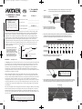
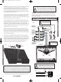
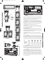
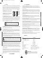
2007 WX 10000-1 q01.qxp
10/29/2007
12:00 PM
Page 1
WX
SUBWOOFERAMPLIFIER
SIGNAL-MODULATEDMONOCHANNEL
WX10000.1
Caution The Kicker WX amplifier outputs extremely high voltage signals
from the voice coil (speaker) outputs and can cause serious injury or death
from electrocution. It is imperative to read the manual carefully and follow all
of the recommended safety precautions before installing the WX amplifier.
©2007 Stillwater Designs
2007 WX 10000-1 q01.qxp
10/29/2007
12:00 PM
Page 2
WX.1SeriesAmplifier
Owner’sManual
Signal-ModulatedMonoChannel
SubwooferAmplifier
WX10000.1
Control Panel Shield
__________________________
Purchase Date:
Please record your purchase
information and keep your sales
receipt for validation of warranty.
WX10000.1
Amplifier Model Number: __________________________
Amplifier Serial Number: __________________________
The Kicker Warhorse amplifier was specifically designed for competition car audio. Sporting 10,000
RMS watts of pure Kicker power, the ultra-high-efficiency design of the WX amplifier revolutionizes
traditional methods of amplification. While most amplifiers use a power supply combined with an
amplification circuit to amplify the audio signal, the Warhorse skips a step by amplifying the audio
signal directly from its patent pending signal-modulated power supply. The signal-modulated power
supply amplifies each polarity of the audio signal separately through its two voice coil outputs to
optimally drive dual-voice coil subwoofers and provide a competitive edge in SPL contests. From gold
plated power connectors and low profile planar transformers to the latest Texas Instruments DSP
technology, no expense was spared to make the Warhorse the most powerful and efficient mono
amplifier in mobile audio.
100
Figure 1
90%
%EFFICIENCY
The patent pending signal-modulated
design of the Warhorse amplifier is the
most powerful and efficient design
available in mobile audio, rated at 90%
efficiency at full power with a 2 ohm load.
The graph compares the Warhorse
amplifier’s efficiency ratings to those of
industry standard Class D amplifiers.
80
2. Remove the control panel shield from the
amplifier so the mounting holes on the bottom
plate of the control panel will be accessible.
3. After determining the best mounting position for the amplifier, use the mounting bracket as a template to drill
nine (9) holes with a 3/16” (4.8mm) bit into the appropriate locations. Attach the bracket to the mounting
location with the nine (9) supplied #10 (5mm) screws inserted through the nine (9) included screw insulators.
Mounting Bracket
Nine (9) Supplied
Screw Insulators
75%
Nine (9) Supplied
#10 (5mm) screws
60
40
KICKER PATENT PENDING SIGNAL-MODULATED DESIGN
20
0
Installation . . . as easy as 1, 2, 3
1. Remove the two (2) screws
securing the control panel
shield to the amplifier chassis.
Authorized Kicker Dealer: __________________________
Congratulations on your
KICKER purchase
INSTALLATION
Model:
Before mounting the amplifier, be sure there is adequate space in the mounting position
to take the control panel shield on or off and to easily access the amplifier’s controls.
Figure 2
HIGH QUALITY CLASS D DESIGN
0.1
0.2
0.5
1.0
2.0
4.0
8.0
4. Slide the Warhorse over the mounting bracket and insert the mounting
bracket into the mounting slot on the bottom of the amplifier.
10
Warhorse Amplifier
POWER OUTPUT (KW)
Before mounting the amplifier, the control panel shield must be removed. The control panel should
remain accessible for adjustment, leaving enough room to access the mounting holes and remove or
attach the control panel shield. Make sure there are no items behind the area where the screws will be
driven. Choose a location that allows at least 4” (10cm) of open ventilation for the amplifier. After
choosing the best location, secure the mounting bracket to the vehicle. Use the bracket as a template
to drill nine (9) holes with a 3/16” (4.8mm) bit into the appropriate locations. Attach the bracket to the
mounting location with the nine (9) supplied #10 (5mm) screws inserted through the nine (9) included
screw insulators.
The amplifier is very heavy.
Assistance may be necessary
to lift and position the amplifier.
Mounting Bracket
INSTALLATION
1. Mounting Choose a structurally sound location to mount your Kicker amplifier. The amplifier should
be mounted as close as possible to the battery network and be electrically isolated from the vehicle
ground. The distance from the battery network to the amplifier should not exceed 48” (122cm). It is
important to mount the amplifier before running any wires or supplying power to the amplifier. The
amplifier secures to the vehicle with an insertable mounting bracket used in combination with two
mounting holes located on the bottom plate of the control panel. You are solely responsible for securely
fastening the WX amplifier in your vehicle.
5. Locate the additional mounting holes on the bottom plate of the control panel. Use the mounting holes as a template
to drill two holes using a 3/16” (4.8mm) bit into the appropriate locations. Secure the bottom plate of the control panel
with the two (2) #10 (5mm) screws. You are solely responsible for securely fastening the amplifier in your vehicle.
Mounting Holes
Next, slide the amplifier over the mounting bracket and into the mounting slot. Make sure the mounting
bracket is properly inserted into the mounting slot and locate the two mounting holes on the bottom
plate of the control panel. Use the mounting holes as a template and drill two (2) holes using a 3/16”
(4.8mm) bit into the appropriate locations. Secure the bottom plate of the control panel with the two (2)
#10 (5mm) screws.
Caution The Kicker WX amplifier outputs extremely high voltage signals
from the voice coil (speaker) outputs and can cause serious injury or death
from electrocution. It is imperative to read the manual carefully and follow all
of the recommended safety precautions before installing the WX amplifier.
2
WX10000.1AMPLIFIER
Control Panel
(Top View)
3
Page 3
The three (3) positive 1/0 gauge power wires should be the last wires connected in the installation.
Install the supplied Kicker three (3) gang ANL fuse holder within 18” (45cm) of the battery network and
in-line with the three (3) power cables connected to the amplifier’s positive power connector. Improper
connections will damage the amplifier and/or cause serious injury or death. If you ever need to remove
the amplifier from the vehicle after it has been installed, the ground wires should be the last wires
disconnected from the amplifier, just the opposite as when you installed it. See Figure 4.
Warning: This amplifier is not like anything you
have ever hooked up before. Pay close
attention to the wiring diagrams in this manual.
Improper connections will damage the amplifier.
+12V
+12V
+12V
+12V
Mount Amplifier within 48”
(122cm) of Battery Network
At least two (2) 200-ampere alternators are
required to power the Warhorse amplifier.
+
Improper connections will damage the
amplifier and/or cause serious injury or
death. Be sure that all wiring is
connected to the appropriate polarity.
-
Power Hood
INSTALLATION
Wire Guide
Negative Power
Connector
Positive Power
Connector
If you have more questions about the installation or operation of your new KICKER product, see the
Authorized KICKER Dealer where you made your purchase. For more advice on installation, click on the
SUPPORT tab on the Kicker homepage, www.kicker.com. Choose the TECHNICAL SUPPORT tab,
choose the product or subject you are interested in, and then view the corresponding information. Please
E-mail [email protected] or call Technical Services (405) 624-8583 for unanswered or specific questions.
Note: To get the best performance from your new Kicker Amplifier, we recommend using genuine Kicker Accessories and Wiring.
All specifications and performance figures are subject to change. Please visit the www.kicker.com for the most current information.
4
250 ampere
fuse
18"
+12V
(45cm)
+12V
250 ampere
fuse
or Less
less
Or
+12V
18"
+12V
ANL fuse holder
contains three (3) 250
ampere fuses. The fuse
holder should be
installed within 18” of
battery network.
(45cm)
(45cm)
Without adequate
charging capability, the
WX amplifier can draw
enough current to shut
down your vehicle’s
computer system. This
may adversely affect
your ability to control
your vehicle.
18"
250 ampere
fuse
250 ampere
fuse
Or less
Less
or
Eight (8) identical, highquality, 800-cca, 12-volt
batteries are recommended
for optimum performance.
or Less
less
Or
Figure 4
Run two (2) ground wires from
separate negative battery
terminals. Ground wires should
connect to vehicle chassis
within 18” of each other.
Figure 3
Fuse Three (3) x 250 Ampere PowerGroundWire Three (3) x 1/0 Gauge
18"
The Warhorse amplifier requires at least two (2) 200-ampere-output-capacity alternators. For each
alternator, connect a 250 ampere fuse within 18” (45cm) of each alternator and a second 250 ampere
fuse within 18” (45cm) of the battery network. Without adequate charging capability, the WX amplifier
can draw enough current to shut down your vehicle’s computer system. This may adversely affect your
ability to control your vehicle. See Figure 4.
ModelWX10000.1
CONFIGURATION
With the control panel shield removed, connect a twisted pair of RCA (low-level) interconnect cable,
carrying the incoming audio signal, to the RCA inputs on the amplifier. Connect the speaker wires to the
supplied AndersonTM connectors. Use 8 gauge wire and strip 9/16” (14mm) from the end being
inserted into the metal contacts. See Figure 5. The wire should be secured by placing the metal contact
into a vise and melting solder inside the metal contact. Then, insert the stripped wire into the molten
solder within the contact. Do not use acid core solder.
3. Configuration The following diagram shows the recommended mono configuration for your
Kicker WX amplifier. The WX amplifier can only drive extremely high-power-rated, dual-voice coil
speakers. We recommend using one or more Kicker SoloX Subwoofers. Each voice coil (speaker)
output is rated at 2 ohms minimum.
(45cm)
From two (2) of the batteries in the battery network, connect 1/0 gauge ground wire from the negative
terminals of the batteries to a paint-free and corrosion-free solid-metal area of the vehicle's chassis.
Make the ground wires short, 18” (45cm) or less. To reduce noise, make sure the ground wires connect
to the same piece of metal and are within 18” (45cm) of each other.
Caution The Kicker WX amplifier outputs extremely high voltage signals
from the voice coil (speaker) outputs and can cause serious injury or death
from electrocution. It is imperative to read the manual carefully and follow all
of the recommended safety precautions before installing the WX amplifier.
Or less
Less
or
2. Wiring Before wiring the Warhorse amplifier, disconnect the vehicle’s batteries to avoid an electrical
short. Eight (8) identical, high-quality, 800-cold-cranking-ampere (cca), 12-volt batteries are
recommended to power the WX amplifier. All power and ground wires should be as short as possible
and utilize 1/0 gauge wire. Remove the wire guide and power hood from the amplifier as shown in
Figure 3. Connect three (3) ground wires from the amplifier’s negative power connector to the negative
terminals of three (3) batteries in the battery network.
18"
12:00 PM
(45cm)
10/29/2007
or Less
less
Or
2007 WX 10000-1 q01.qxp
WX10000.1AMPLIFIER
The WX amplifier outputs dangerous voltage levels from the voice
coil (speaker) outputs and can cause serious injury or death from
electrocution. Never contact the voice coil outputs, connect
speakers, or contact speaker wires while the amplifier is turned on.
Strip Wire
9/16” (14mm)
Figure 5
AndersonTM Connector
8 Gauge Speaker Wire
Secure wire to metal
contacts by soldering.
Metal Contacts
5
2007 WX 10000-1 q01.qxp
10/29/2007
12:00 PM
Page 4
Four (4) 2 ohm Dual-Voice Coil Subwoofers
The WX amplifier outputs dangerous voltage levels
from the voice coil (speaker) outputs and can cause
serious injury or death from electrocution. Never
contact the voice coil outputs, connect speakers, or
contact speaker wires while the amplifier is turned on.
Figure 6
Voice Coil 1
Figure 8
Voice Coil 2
Minimum
2 Ohm
Load
Minimum
2 Ohm
Load
-
+
-
+
2 Ohm Dual-Voice Coil Subwoofer
Voice Coil 1
+
Voice Coil 2
Minimum
2 Ohm
Load
Coil 1
Minimum
2 Ohm
Load
-
+
-
+
Wiring Key
-
-
Voice Coil 1 +
+
CONFIGURATION
Operation
Voice Coil 1 Coil 2
Coil 1
Voice Coil 2 +
Within the control panel shield, the Kicker WX amplifier has five (5) rotary controls, input jacks for the
Remote Bass level control, and input/output jacks for the optional WX control module. The control
panel delivers a full range of options for processing the signal that powers your subwoofers. To remove
the control panel shield, simply remove the two (2) screws as shown in Figure 5.
+
Voice Coil 2 -
-
-
Series Wire
+
Use 8 Gauge Speaker Wire
Coil 1
Coil 2
+
Use 8 Gauge Speaker Wire
-
Coil 2
+
Two (2) 4 ohm Dual-Voice Coil Subwoofers
Voice Coil 1
Coil 1
Minimum
2 Ohm
Load
+
-
2. BassBoostControl The bass boost control is designed to give you increased output 0 - 18dB
at 40 Hz. The setting for this control is subjective. If you turn it up, you must go back and adjust the
input gain control to avoid clipping the amplifier.
+
Voice Coil 2
Minimum
2 Ohm
Load
+
-
+
+
-
-
Coil 2
Coil 1
Coil 1
-
-
-
+
Coil 1
+
+
3. HighPassSubsonicCrossover The variable high-pass crossover located on the control panel
utilizes a 24dB per octave 20 - 60Hz high-pass crossover. The setting for this control is subjective but
should be adjusted to appropriately accommodate your enclosure in order to prevent damage from high
excursion and increase the power handling of the subwoofer(s).
4. LowPassCrossover The variable low-pass crossover located on the control panel utilizes a
24dB per octave 50 - 200Hz low-pass filter. The setting for this control is subjective; 80 Hz is a good
place to start.
+
Coil 2
Coil 2
1. InputGainControl The input gain control is not a volume control. It matches the output of the
source unit to the input level of the amplifier. Please use hearing protection before performing the
following procedure. Disconnect the Remote Bass level control and turn the source unit up to about
3/4 volume (if the source unit goes to 30, turn it to 25). Next, slowly turn (clockwise) the gain on the
amplifier up until you can hear audible distortion, then turn it down a little.
-
-
Coil 2
+
Figure 9
Use 8 Gauge Speaker Wire
Figure 7
Back View
Slide the
housing until
it snaps into
the metal
bracket
6
1.6
V
3.5
Side View
Voice Coil 2
WX10000.1AMPLIFIER
4 Conductor
Phone Cable
40
9
0.4
5
Mount the metal bracket
Voice Coil 1
0.8
The corresponding value for
each marker is given for each of
the Warhorse amplifier’s rotary
controls to assist in the precise
adjustment of your system.
0.25
0.17
5.5
12.5
dB
2.5
0
15
18
45
Hz
25
20
30
125
30
55
60
95
155
Hz
70
50
185
200
50
80
20
%RMS
100
OPERATION
Use 8 Gauge Speaker Wire
5. AdjustableLimiterControl The limiter adjusts the maximum RMS output of the Warhorse. If your
vehicle’s charging system is inadequate to provide full power to the WX series amplifier, adjust the limiter
control clockwise to reduce the amplifier’s power consumption and maintain an operational level that will
protect your subwoofer(s) from damage. If the <VOLT LED is on and the amplifier is frequently shutting
down due to under voltage, try turning the limiter control up (clockwise) until this is no longer a problem.
15
10
6. RemoteBass(Level Control) With the remote bass level control, you have the ability to control the
level of the subwoofer(s) remotely. To mount the remote bass level control, simply screw the metal
bracket to the chosen location. Then slide the housing onto the bracket until it snaps into place. Run
the cable from the controller to the “Remote Bass” jack on the amplifier chassis. See Figure 6.
7. WarhorseControlModule The optional Warhorse control module opens up a wide range of
operational possibilities within the Warhorse. The control module can simultaneously control up to 16
WX amplifiers and puts additional signal processing features in the palm of your hand. These include
bandpass crossover with adjustable slopes, limiter adjustment, phase inversion, single-band parametric
equalization, voltage range adjustment, battery voltage display, tone generator, and individual amplifier
muting. Contact your Kicker dealer for more information about the Warhorse control module and its
features. It is necessary to purchase the control module to access the full range of possibilities available
from your Kicker Warhorse amplifier.
7
2007 WX 10000-1 q01.qxp
10/29/2007
12:00 PM
Page 5
TroubleShooting
WarhorseDesignFeatures
If your amplifier does not appear to be working, check the obvious things first: such as blown fuses,
poor or incorrect wiring connections, incorrect setting of crossover switch and gain controls, etc. There
are eight LEDs on the control panel of your Kicker WX series amplifier. The LED display may help
identify the problem. The amplifier’s protection circuitry induces a muted safe mode if any excessive
conditions have occurred outside of the amplifier’s normal operational range. These conditions are
indicated by the LEDs on the amplifier’s control panel.
Figure 10
1. PWR LED on/off Smart power indicator turns
on when the amplifier is on and functioning properly.
2. NET LED on/off Indicates the optional remote
control module is connected to the Control Module
DIN input on the amplifier. See Figure 8.
The Warhorse LED array
displays the status of the
amplifier’s protective
circuitry and can assist in
troubleshooting problems
that may occur while using
the amplifier. The green
LED’s will turn on or off
depending on the
conditions listed in this
section.
Without adequate charging capability, the WX amplifier can draw
enough current to shut down your vehicle’s computer system.
This may adversely affect your ability to control your vehicle.
4. >VOLT LED on/off The Over Voltage LED turns on when the voltage supplied to the amplifier
exceeds 16 volts and the muted safe mode has been activated. After the voltage supply drops below
15.5 volts, the amplifier will automatically turn back on.
5. X-BNDW LED on/off Because of the combined high pass and low pass filters built into the
rotary control section of the amplifier, it is possible to cause a reduction in output by adjusting the
bandwidth too narrow or overlapping the high and low pass crossover frequencies. The X-BNDW LED
turns on if this has occurred and is causing a reduction in output.
OPERATION
6. >TEMP LED on/off If the temperature of the amplifier’s heatsink exceeds 158F (70C), it will
activate the muted safe mode. When the temperature decreases to 149F (65C), the amplifier will
automatically turn back on. If this LED is on, turn the amplifier off and test resistance at the speaker
terminals with a digital multimeter (see Figure 6 in this manual for multiple speaker wiring suggestions).
Also, check for adequate airflow around the amplifier.
The WX amplifier outputs dangerous voltage levels from the voice coil (speaker) outputs.
Never contact the voice coil outputs, connect speakers, or speaker wires if the amplifier is
turned on. Turning the amplifier on without loading both voice coil outputs or connecting
the speaker(s) will increase the risk of electrical shock and could damage the amplifier.
7. Short LED on/off The short LED will light up if the electrical current coming out of the amplifier’s
voice coil (speaker) outputs exceeds a peak of 130 ampere. The Warhorse Amplifier tests the outputs
every three (3) seconds to protect the amplifier from electrical shorts and will turn off automatically if any
short is detected. With the amplifier turned off and speakers disconnected, check for speaker wires
shorted to each other or to the vehicle’s chassis. Check for damaged speaker(s), or speaker(s)
operating below the minimum recommended impedance. Because of the dangerous voltage output of
the amplifier, it is important to turn the amplifier off before attempting to repair any short or problem with
the voice coil output wiring.
8. Service LED on/off If the service LED turns on, the amplifier most likely requires repair. In some
cases, the service LED will illuminate if the voice coil (speaker) outputs are not both loaded at the same
time. Turn the amplifier off and check the wiring for abrasions. Make sure that the amplifier is wired
correctly to the speakers as indicated in Figure 6. If no problems are found with the speaker wire or
connections and the service LED remains on, contact the Authorized Kicker dealer from whom you
purchased the amplifier.
8
WX10000.1AMPLIFIER
2. Planar Transformer Design The WX amplifier’s four (4) planar transformers are excellent for high
power applications and are custom designed to handle 5,000 watts each, leaving more than enough
power headroom to operate reliably and consistently at full RMS with 20,000 watts of total capability.
3. Texas Instruments DSP The Warhorse uses the latest Texas Instruments industrial grade DSP to
handle the amplifier’s pulse-width modulation, manage signal processing, and control the amplifier’s
protection circuitry.
4. Insulated Metal Substrate Cooling The Warhorse design uses insulated aluminum material for
optimum heat transfer between power devices and the heatsink. Lower operating temperatures improve
performance and durability while allowing for a smaller overall footprint.
5. Heavy Duty Industrial Bus Bars The Warhorse has been outfitted with solid copper industrial grade
bus bars. With 70 square millimeters of cross sectional area, the WX amplifier’s heavy duty bus bars are
specifically engineered to maximize the current carrying capability within the amplifier.
6. Super Thick, 4 Ounce Double Sided PCB When you are livin’ this loud, you have to have a strong
foundation. The circuit board used in the Warhorse is 50% thicker than the industry standard and uses
the heaviest available 4 ounce thick copper traces and plated-through holes. This assures the circuit
board can transfer the current needed for an amplifier of this magnitude.
PERFORMANCE
3. <VOLT LED on/off The Under Voltage LED
turns on when the voltage supplied to the amplifier drops below 9 volts. The amplifier will remain in the
muted safe mode until the voltage supply increases to 9.5 volts. If the amplifier goes into mute mode
often, as a result of under voltage, you may need to do one or more of the following: a) turn up the
limiter control on the amplifier’s control panel, b) check the connections, c) replace batteries with
identical units or charge existing batteries, d) add additional identical batteries to the vehicle’s battery
network, e) add an additional alternator to your vehicle.
1. Patent Pending Signal-Modulated Power Supply The WX amplifier’s patent pending signal
modulated power supply combined with its custom planar transformers achieves efficiency ratings yet
to be matched in mobile audio, operating at 90% efficiency at a 2 ohm load and 93% efficiency at a 4
ohm load at full power.
7. Oversized Gold Plated Power Connectors The Warhorse amplifier’s gold plated power connectors
were custom designed with multiple power terminals to maximize current carrying capability to the
amplifier’s signal-modulated power supply.
8. Industrial Grade AndersonTM Speaker Connectors The 50 ampere AndersonTM connectors
packaged with the Warhorse amplifier allow minimal contact resistance at high current. The housing of
the connectors was designed to prevent polarity mismatches when connecting speakers and also
protects fingers or probes from touching the metal contacts to provide additional safety from the high
voltage signals coming from the voice coil (speaker) outputs.
9. Dual Thermostatically-Controlled Push-Pull Cooling Fans Twin push-pull fans are mounted on the
side of the amplifier to improve airflow and provide additional cooling for the amplifier.
Performance
Model
WX10000.1
RMS Power in Watts
@14.4V, 2Ω Mono, ≤1.5% THD+N
@14.4V, 4Ω Mono, ≤1.5% THD+N
Length:
Height:
Width:
Weight:
Frequency Response, + 0 / - 1 dB:
Signal-to-Noise Ratio:
Input Sensitivity:
Low Pass Crossover:
High Pass Sub-Sonic Crossover:
Bass Boost:
10000 x 1
5000 x 1
35” (888mm)
3 3/4” (96mm)
17 3/4” (450mm)
66.8 lb (30.3kg)
20 Hz - 200 Hz
>95 dB, a-weighted, re: rated power
170 mV - 5 V low level,
Variable Low-Pass, 50 - 200Hz, 24dB per octave
Variable High Pass, 20 - 60Hz, 24dB per octave
Variable 0 to +18 dB boost @ 40 Hz
Model WX10000.1
5000 x 1 @ 4 ohms, 14.4Vdc, 1% THD, CEA-2006 (Watts)
Signal to Noise Ratio -60 CEA-2006 (ref: 1W, A-weighted)
9
2007 WX 10000-1 q01.qxp
10/29/2007
12:00 PM
Page 6
WARRANTY
WarhorseLimitedWarranty
InternationalWarranty
KICKER warrants this product to be free from defects in material and workmanship under normal use for a period of
THREE (3) MONTHS from date of original purchase with receipt. When purchased from an Authorized KICKER Dealer
it is warranted for TWO (2) YEARS from date of original purchase with receipt. In all cases you must have the original
receipt. Should service be necessary under this warranty for any reason due to manufacturing defect or malfunction
during the warranty period, KICKER will repair or replace (at its discretion) the defective merchandise with equivalent
merchandise at no charge. Warranty replacements may have cosmetic scratches and blemishes. Discontinued
products may be replaced with more current equivalent products.
Contact your International KICKER dealer or distributor concerning specific procedures for your country's warranty
policies.
This warranty is valid only for the original purchaser and is not extended to owners of the product subsequent to the
original purchaser. Any applicable implied warranties are limited in duration to a period of the express warranty as
provided herein beginning with the date of the original purchase at retail, and no warranties, whether express or
implied, shall apply to this product thereafter. Some states do not allow limitations on implied warranties; therefore
these exclusions may not apply to you. This warranty gives you specific legal rights; however you may have other
rights that vary from state to state.
GARANTÍA INTERNACIONAL
WHAT TO DO IF YOU NEED WARRANTY OR SERVICE
Defective merchandise should be returned to your local Authorized KICKER Dealer for warranty service. Assistance in
locating an Authorized Dealer can be found at www.kicker.com or by contacting KICKER directly. You can confirm that
a dealer is authorized by asking to see a current authorized dealer window decal.
If it becomes necessary for you to return defective merchandise directly to Stillwater Designs (KICKER), call the
KICKER Customer Service Department at (405) 624-8510 for a Return Merchandise Authorization (RMA) number.
Package all defective items in the original container or in a package that will prevent shipping damage, and return to:
Stillwater Designs, 5021 North Perkins Road, Stillwater, OK 74075
The RMA number must be clearly marked on the outside of the package. Please return only defective components.
The return of functioning items increases your return freight charges. Non-defective items will be returned freightcollect to you.
Include a copy of the original receipt with the purchase date clearly visible, and a "proof-of-purchase" statement listing
your name and return shipping address, the Dealer's name and invoice number, and product purchased. Warranty
expiration on items without proof-of-purchase will be determined from the type of sale and manufacturing date code.
Freight must be prepaid; items sent freight-collect, or COD, will be refused.
WHAT IS NOT COVERED?
HOW LONG WILL IT TAKE?
KICKER strives to maintain a goal of 72-hour service for all electronics (amplifiers, crossovers, equalizers, etc.) returns.
Delays may be incurred if lack of replacement inventory or parts is encountered.
VersiónEspañol
Comuníquese con su concesionario o distribuidor KICKER internacional para obtener infor ación sobre procedimientos
específicos relacionados con las normas de garantía de su país.
ADVERTENCIA: Los excitadores KICKER son capaces de producir niveles de sonido que pueden dañar
permanentemente el oído. Subir el volumen del sistema hasta un nivel que produzca distorsión es más dañino para el
oído que escuchar un sistema sin distorsión al mismo volumen. El dolor es siempre una indicación de que el sonido es
muy fuerte y que puede dañar permanentemente el oído. Sea precavido cuando controle el volumen.
La frase "combustible para vivir la vida Livin' Loud™ a todo volumen" se refiere al entusiasmo por la vida que la marca
KICKER de estéreos de automóvil representa y a la recomendación a nuestros clientes de que vivan lo mejor posible
("a todo volumen") en todo sentido. La línea de altavoces y amplificadores KICKER es la mejor del mercado de audio
de automóviles y por lo tanto representa el "combustible" para vivir a todo volumen en el área de "estéreos de
automóvil" de la vida de nuestros clientes. Recomendamos a todos nuestros clientes que obedezcan todas las reglas
y reglamentos locales sobre ruido en cuanto a los niveles legales y apropiados de audición fuera del vehículo.
INTERNATIONALE GARANTIE
DeutscheVersion
Nehmen Sie mit Ihren internationalen KICKER-Fachhändler oder Vertrieb Kontakt auf, um Details über die
Garantieleistungen in Ihrem Land zu erfahren.
WARNUNG: KICKER-Treiber können einen Schallpegel erzeugen, der zu permanenten Gehörschäden führen kann!
Wenn Sie ein System auf einen Pegel stellen, der hörbare Verzerrungen erzeugt, schadet das Ihren Ohren mehr, als ein
nicht verzerrtes System auf dem gleichen Lautstärkepegel. Die Schmerzschwelle ist immer eine Anzeige dafür, dass
der Schallpegel zu laut ist und zu permanenten Gehörschäden führen kann. Seien Sie bei der Lautstärkeeinstellung
bitte vernünftig!
Der Slogan "Treibstoff für Livin' Loud" bezieht sich auf die mit den KICKER-Autostereosystemen assoziierte
Lebensfreude und die Tatsache, dass wir unsere Kunden ermutigen, in allen Aspekten ihres Lebens nach dem Besten
("Livin' Loud") zu streben. Die Lautsprecher und Verstärker von KICKER sind auf dem Markt für Auto-Soundsysteme
führend und stellen somit den "Treibstoff" für das Autostereoerlebnis unserer Kunden dar. Wir empfehlen allen unseren
Kunden, sich bezüglich der zugelassenen und passenden Lautstärkepegel außerhalb des Autos an die örtlichen
Lärmvorschriften zu halten.
GARANTIE INTERNATIONALE
VersionFrançaise
Pour connaître les procédures propres à la politique de garantie de votre pays, contactez votre revendeur ou
distributeur International KICKER.
GARANTIE
This warranty is valid only if the product is used for the purpose for which it was designed.
It does not cover:
o Damage, serious injury, or death to the installer, user, or listener.
o Damage due to improper installation.
o Subsequent damage to other components, the vehicle, installer, user, or listener.
o Damage caused by exposure to moisture, excessive heat, chemical cleaners, and/or UV radiation.
o Damage through negligence, misuse, accident or abuse. Repeated returns for the same damage may be
considered abuse.
o Any cost or expense related to the removal or reinstallation of product.
o Speakers damaged due to amplifier clipping or distortion.
o Items previously repaired or modified by any unauthorized repair facility.
o Return shipping on non-defective items.
o Products with tampered or missing barcode labels.
o Products returned without a Return Merchandise Authorization (RMA) number.
o Freight Damage.
o The cost of shipping product to KICKER.
o Service performed by anyone other than KICKER.
WARNING: KICKER products are capable of producing sound levels that can permanently damage your hearing!
Turning up a system to a level that has audible distortion is more damaging to your ears than listening to an
undistorted system at the same volume level. The threshold of pain is always an indicator that the sound level is too
loud and may permanently damage your hearing. Please use common sense when controlling volume.
AVERTISSEMENT: Les haut-parleurs KICKER ont la capacité de produire des niveaux sonores pouvant endommager
l'ouïe de façon irréversible ! L'augmentation du volume d'un système jusqu'à un niveau présentant une distorsion
audible endommage davantage l'ouïe que l'écoute d'un système sans distorsion au même volume. Le seuil de la
douleur est toujours le signe que le niveau sonore est trop élevé et risque d'endommager l'ouïe de façon irréversible.
Réglez le volume en faisant prevue de bon sens !
L'expression " carburant pour vivre plein pot " fait référence au dynamisme de la marque KICKER d'équipements
audio pour véhicules et a pour but d'encourager nos clients à faire le maximum (" vivre plein pot ") dans tous les
aspects de leur vie. Les haut-parleurs et amplificateurs KICKER sont les meilleurs dans le domaine des équipements
audio et représentent donc pour nos client le " carburant pour vivre plein pot " dans l'aspect " installation audio de
véhicule " de leur vie. Nous encourageons tous nos clients à respecter toutes les lois et réglementations locales
relatives aux niveaux sonores acceptables à l'extérieur des véhicules.
Failure to follow these steps may void your warranty. Any questions can be directed to the KICKER Customer Service
Department at (405) 624-8510.
P.O. Box 459 • Stillwater, Oklahoma 74076 • U.S.A. • (405) 624-8510
10
WX10000.1AMPLIFIER
10292007q+07WX
11