1
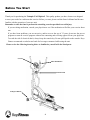
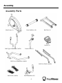
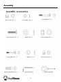
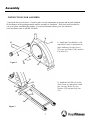
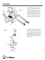
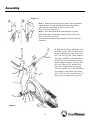
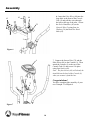
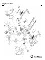
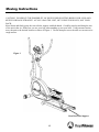
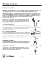
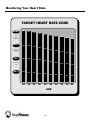
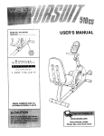
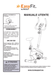
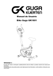
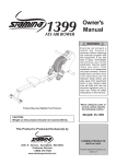
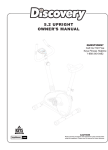
Owner’s Manual
Triumph 5.3e Elliptical
Customer Service
(888) 340-0482
Keys Fitness Products
4009 Distribution Drive
Suite 250
Garland, TX 75041
www.keysfitness.com
315-00021
06/05 Rev B
Table of Contents
Important Safety Information
3
Before You Start
4
Assembly
5-10
Exploded View
11
Parts List
12
Moving Instructions
13
Warm Up Exercises
14
Target Heart Rate Zone
15-16
Warranty
17
2
Important Safety Information
WARNING! Before using this unit or starting any exercise program, consult your physician. This is especially important for persons over the age of 35 and/or persons with pre-existing health problems. The manufacturer or distributor assumes no responsibility for personal injury or property damage sustained by or through
the use of this product.
WARNING! To reduce the risk of electrical shock, burns, fire, or other possible injuries to the user, it is important to review this manual and the following precautions before operation.
SAFETY PRECAUTIONS AND TIPS
1. It is the owner’s responsibility to ensure that all users of this unit have read the Owner’s Manual and are
familiar with warnings and safety precautions.
2. This unit has a user maximum capacity of 250 pounds.
3. The unit should only be used on a level surface and is intended for indoor use only. The unit should not
be placed in a garage, patio, or near water and should never be used while you are wet. Keys recommends a
mat be placed under the unit to protect floor or carpet and for easier cleaning.
4. Wear comfortable, good-quality walking or running shoes and appropriate clothing. Do not use the unit
with bare feet, sandals, socks or stockings.
5. Always examine your unit before using to ensure all parts are in working order.
6. Allow the unit to fully stop before dismounting.
7. Pets should never be allowed near the unit.
8. Do not leave children unsupervised near or on the unit.
9. Never operate the unit where oxygen is being administered, or where aerosol products are being used.
10. Never insert any object or body parts into any opening.
11. For safety and to prevent damage to your unit, no more than one person should use the unit at a time.
12. Failure to follow these instructions will void the unit warranty.
3
Before You Start
Thank you for purchasing the Triumph 5.3e Elliptical! This quality product you have chosen was designed
to meet your needs for cardiovascular exercise. Before you start, please read the Owner's Manual and become
familiar with the operation of your new unit.
Remember to take the time to perform the stretching exercises provided to avoid injury.
If you are taking medication, consult your physician to see if the medication will affect your exercise heart
rate.
If you have heart problems, you are not active, and/or are over the age of 35 years, do not use the pre-set
programs or start an exercise program without first contacting and receiving approval from your physician.
To avoid the risk of electrical shock, always keep the console dry. Do not spill liquids on the console. Keys
Fitness recommends a sealed water bottle for beverages consumed while using the unit.
Please review the following drawing below to familiarize yourself with the listed parts.
Console
Pulse Handlebars
Tension Knob
Transport Wheels
4
Assembly
Assembly Parts
Main Frame (1)
Front Stabilizer (54)
Rail Tube (2)
Console (9)
L&R Upper Handlebars (7a&7b)
Console Tube (3)
L&R Lower Handlebars (6a&6b)
L&R Foot Pedals (4a&4b)
L&R Pedals (5a&5b)
Pulse Handlebars (85)
5
Assembly
Assembly Accessories
M8 Cap Nut (33) - 4
Hex Head Bolt (47) - 4
Carriage Bolt (62) - 4
HEX HEAD BOLT (65) - 8
Arc Washer (34) - 12
Carriage Bolt (35) - 4
Washer (48) - 4
Nylon Locknut (49) - 4
Washer (63) - 4
ALLEN WENCH
6
M6 Cap Nut (64) - 4
SCREW DRIVER
Assembly
INSTRUCTIONS FOR ASSEMBLY:
Unpack the box in a clear area. Check to make sure all components are present and in good condition.
Do not dispose of the packing material until the assembly is completed. Tools have been provided for
you to use when assembling the product. If you need assistance please go to our website at
www.keysfitness.com or call 888-340-0482.
34
33
35
1. Attach the Front Stabilizer (54)
onto Main Frame (1) and secure in
place with two Carriage Screws
(35), two Arc Washers (34), and two
Cap Nuts (33).
54
34
Figure 1
33
1
33
2. Install the Rail Tube (2) to the
Main Frame (1) and secure it with
two Carriage Bolts (35), two
Washers (34), and two Cap Nuts
(33).
34
33
34
35
2
Figure 2
7
Assembly
50
3. Attach the Left Pedal (5a) to Left
Pedal Tube (4a) and secure in place
with two Hex Head Bolts (47), two
Nylock Nuts (49), and two Washers
(48). Next, insert the Left Pedal Tube
(4a) into the U Bracket (53) and use
Hex Head Bolt (50), Washer (48), and
Nylock Nut (49). Repeat previous
directions to complete the right side.
Figure 3
53
47
48
5a
49
4a
4. Connect the Extension Wire (72) to
Sensor Wire (73). Next, connect the
Tension Cable (68) to the Tension Knob
(66). (Refer to Figure 4a on the next
page) Slide the Console Tube (3) onto
the Main Frame (1) and secure in place
using four Washers (34) and four Hex
Head Bolt (65).
Figure 4
3
34
34
65
65
72
73
66
68
8
Assembly
Figure 4a
68
68
66
66
Step 1: With the Tension Knob (66) on the lowest resistance
setting number 1, insert the ball end of the tension knob
cable into the spring hook on Tension Cable (68).
Refer to Picture A for Step 1.
Step 2: Take the tension knob cable and pull it up and
between the gap of the bracket on the Tension Cable (68).
Refer to Picture B for Step 2.
You can raise the tension by turning the Tension Knob (66)
clockwise.
7a
7b
64
63
46
44
6b
62
45
6a
40
36
27
71 43
Figure 5
9
5. Slide the Left Lower Handlebar (6a)
on to the Console Tube (3) and secure it
in place using Washer (46), Nylock Nut
(45), and Nut Cap (44). Next, slide the
Left Upper Handlebar (7a) into the top
of the Left Lower Handlebar (6a) and
fasten in place using two Carriage Bolts
(62), two Washers (63), and two Cap
Nuts (64). Assemble the Connecting
Tube (43) and the Lower Left Handlebar
(6a) using Hex Head Bolt (40), Washer
(36), Nylock Nut (27), and Nut Cap (71).
Repeat step to complete the right side.
Assembly
85
65
6. Insert the Pulse Wires (88) into the
large hole at the front of the Console
Tube (3) and pull the wires through
the hole at the top of the tube. Secure
the Pulse Handlebar (85) to the
Console Tube (3) using four Arc
Washers (34) and four Hex Head
Bolts (65).
88
72
34
3
Figure 6
7. Connect the Sensor Wire (72) and the
Pulse Wires (88) to the Console (9). Then
attach the Console (9) to the top of the
Console Tube (3) and secure it in place
using four Screws (69).
Note: The four Screws (69) will already be
installed into the back of the Console (9)
when you remove it from the box.
9
88
Congratulations!
You have completed the assembly of your
new Triumph 5.3e Elliptical.
72
69
Figure 7
10
Exploded View
11
Parts List
TRI5.3e Parts List Rev B
REF #
PART #
1
323-00270
DESCRIPTION
MAIN FRAME TRI-5.3E
QTY
1
REF #
PART #
44 302-01110
DESCRIPTION
NUT CAP TRI-5.3E
QTY
6
2
323-00271
RAIL TUBE TRI-5.3E
1
45
302-01111
NYLOCK NUT TRI-5.3E
6
3
323-00272
CONSOLE TUBE TRI-5.3E
1
46
302-01112
WASHER 13*26*2 TRI-5.3E
8
4a
323-00273
LEFT PEDAL TUBE TRI-5.3E
1
47
302-01113
HEX HEAD BOLT 3/8"*45 TRI-5.3E
4
4b
323-00274
RIGHT PEDAL TUBE TRI-5.3E
1
48
302-01114
WASHER 10*26*2 TRI-5.3E
6
5a
323-00275
LEFT PEDAL TRI-5.3E
1
49
302-01115
NYLOCK NUT 3/8" TRI-5.3E
6
5b
323-00276
RIGHT PEDAL TRI-5.3E
1
50
302-01116
HEX HEAD BOLT 3/8"*50 TRI-5.3E
2
6a
323-00277
LEFT LOWER HANDLEBAR TRI-5.3E
1
51
302-01117
BUSHING CHROME TRI-5.3E #51
4
6b
323-00278
RIGHT LOWER HANDLEBAR TRI-5.3E
1
52
302-01118
BUSHING CHROME TRI-5.3E #52
4
7a
323-00279
LEFT UPPER HANDLEBAR TRI-5.3E
1
53
319-00131
U BRACKET, TRI-5.3E
2
7b
323-00280
RIGHT UPPER HANDLEBAR TRI-5.3E
1
54
323-00283
FRONT STABILIZER TRI-5.3E
1
8
304-00007
BELT, J6-400
1
55
306-00473
MOVING TUBE CAP, TRI-5.3E/8.3E
2
9
307-00068
CONSOLE, TRI 5.3
1
56
302-01119
SMALL SPACER TRI-5.3E
4
10
311-00063
PULLEY, TRI-5.3E
1
57
331-00082
BEARING TRI-5.3E #57
4
11
331-00080
OUTSIDE BEARING COLLAR TRI-5.3E
1
58
306-00474
WHEEL, TRI-5.3E/8.3E
2
12
302-01086
BIG WASHER TRI-5.3E
1
59
302-01120
BIG SPACER TRI-5.3E
2
2
13
330-00063
AXLE FOR PULLEY, TRI-5.3E
1
60
306-00481
PLASTIC ROLL TRI-5.3E
14a
330-00064
LEFT CRANK, TRI-5.3E
1
61
306-00482
PLASTIC ROLL TRI-5.3E
2
14b
330-00065
RIGHT CRANK ,TRI-5.3E
1
62
302-01121
CARRIAGE BOLT M6*35 TRI-5.3E
4
15
302-01087
NYLOCK NUT M10 TRI-5.3E
2
63
302-01122
WASHER 6*13*1 TRI-5.3E
4
16
302-01088
C CLIP TRI-5.3E
1
64
302-01123
CAP NUT M6 TRI-5.3E
4
17
331-00009
BEARING 6003ZZ
2
65
302-01124
HEX HEAD BOLT M8*15
8
18
311-00064
FLYWHEEL, TRI-5.3E
1
66
310-00157
TENSION KNOB, TRI-5.3E
1
19
331-00005
BEARINGS 6000Z
2
67
302-01125
BOLT TRI-5.3E #66
1
20
302-01089
SPACER FOR FLYWHEEL TRI-5.3E
1
68
310-00158
TENSION CABLE, TRI-5.3E
1
21
302-01090
BC NUT 3/8" TRI-5.3E
1
69
302-01126
BOLT TRI-5.3E #69
2
22
302-01091
ZIP SET TRI-5.3E
2
70
302-01127
SPACER 12.7*37.1 TRI-5.3E
2
23
302-01092
WASHER 10*19*1.5 TRI-5.3E
1
71
302-00173
NUT CAP
4
24
302-01093
NUT 3/8" TRI-5.3E
1
72
313-00125
EXTENSION WIRE, TRI-5.3E
1
25
330-00066
AXLE FOR FLYWHEEL, TRI-5.3E
1
73
313-00126
SENSOR WIRE, TRI-5.3E
1
26
331-00081
GREASED BEARING TRI-5.3E #26
1
74
302-01129
SCREW M4*11 TRI-5.3E
1
27
302-01094
NYLOCK NUT M8 TRI-5.3E
8
75
310-00159
FOAM GRIP, TRI-5.3E
2
28
302-01095
ARC SPRING TRI-5.3E
1
76
306-00431
HANDLEBAR CAP, TRI-5.3E, 8.3E
2
29
302-01096
ARC PLATE TRI-5.3E
1
77
306-00475
LEFT HOUSING, TRI-5.3E/8.3E
1
30
302-01097
HEX HEAD BOLT M8*60 TRI-5.3E
2
78
306-00476
RIGHT ROUND COVER, TRI-5.3E/8.3E
1
31
302-01098
NUT M8 TRI-5.3E
2
79
306-00477
RIGHT HOUSING TRI-5.3E
1
32
302-01099
MAGNET TRI-5.3E
1
80
306-00478
LEFT ROUND COVER TRI-5.3E
1
33
302-01100
CAP NUT M8 TRI-5.3E
4
81
302-01130
SCREW M4*16 TRI-5.3E
4
34
302-01101
ARC WASHER 8*19*1.5 TRI-5.3E
12
82
302-01131
BOLT M5*12 TRI-5.3E
4
35
302-01102
CARRIAGE BOLT M8*60 TRI-5.3E
4
83
302-01132
SCREW M4*44 TRI-5.3E
3
36
302-01103
WASHER 8*19*1.5 TRI-5.3E
6
84
306-00479
WHEEL CAP, TRI-5.3E
2
37
302-01104
HEX HEAD BOLT M8*40 TRI-5.3E
2
85
323-00284
PULSE HANDLEBAR TRI-5.3E
1
38
302-01105
BUSHING CHROME TRI-5.3E
8
86
310-00160
FOAM GRIP, TRI-5.3E
2
39
323-00281
U CONNECT TUBE TRI-5.3E
2
87
306-00480
HANDLEBAR CAP TRI-5.3E
2
40
302-01107
HEX HEAD BOLT M8*55 TRI-5.3E
4
88
313-00127
HAND PULSE WIRE, TRI-5.3E
2
41
302-01108
LOWER HANDLEBAR CAP TRI-5.3E
2
#
302-01134
BOLT PACK TRI-5.3E
1
42
302-01109
BUSHING CHROME TRI-5.3E
4
#
315-00021
OWNER'S MANUAL TRI-5.3E
1
43
323-00282
CONNECTING TUBE TRI-5.3E
2
12
Moving Instructions
CAUTION! TO REDUCE THE POSSIBILITY OF INJURY WHILE LIFTING, BEND YOUR LEGS AND
KEEP YOUR BACK STRAIGHT. AS YOU LEAN THE UNIT, LIFT USING YOUR LEGS, NOT YOUR
BACK.
Kneel down and firmly grasp the rear rail tube support with both hands. Carefully stand up and bring the rear
of the unit in the air. Make sure you use your legs when standing up, not your back. Using extreme caution,
move the unit to the desired location as shown in Figure 1. Do not attempt to move the unit over an uneven or
rough surface.
Figure 1
Rear Rail Tube Support
13
Warm Up Exercises
EXERCISE GUIDELINES
WARNING! Before beginning this or any exercise program, you should consult your physician. This is especially important for individuals over the age of 35 or individuals with pre-existing health problems.
Warming up prepares the body for the exercise by increasing circulation, supplying more oxygen to the muscles and raising body temperature. Begin each workout with 5 to 10 minutes of stretching and light exercise
to warm up. The photos on this page show several forms of basic stretching you may perform before your
workouts. In order to achieve an adequate warm-up, perform each stretch three times.
TOE TOUCH STRETCH
Stand bending your knees slightly and slowly bend forward from your hips.
Allow your back and shoulders to relax as you reach down toward your toes
as far as possible. Hold for 15 counts, then relax. This will stretch your hamstrings, back of knees, and back.
HAMSTRING STRETCH
Sit with one leg extended. Bring the sole of the opposite foot toward you and
rest it against the inner thigh of your extended leg. Reach toward your toes as
far as possible. Hold for 15 counts, then relax. This will stretch your hamstrings, lower back, and groin.
CALF/ACHILLES STRETCH
With one leg in front of the other, reach forward and place your hands against
a wall. Keep your back leg straight and your back foot flat on the floor. Bend
your front leg, lean forward and move your hips toward the wall. Hold for 15
counts, then relax. To cause further stretching of the Achilles tendon, bend
your back leg as well. This will stretch your calves, Achilles tendons, and
ankles.
QUADRICEPS STRETCH
With one hand against a wall for balance, reach back and grasp one foot with
your other hand. Bring your heel as close to your buttocks as possible. Hold
for 15 counts, then relax. This will stretch your quadriceps and hip muscles.
INNER THIGH STRETCH
Sit with the soles of your feet together and your knees outward. Pull your
feet toward your groin area as far as possible. Hold for 15 counts, then relax.
This will stretch your quadriceps and hip muscles.
14
Monitoring Your Heart Rate
Monitoring Your Heart Rate
To obtain the greatest cardiovascular benefits from your exercise workout, it is important to work within your
target heart rate zone. The American Heart Association (AHA) defines this target as 60%-75% percent of your
maximum heart rate.
Your maximum heart rate may be roughly calculated by subtracting your age from 220. Your maximum heart
rate and aerobic capacity naturally decreases as you age. This may vary from one person to another, but use
this number to find your approximate effective target zone. For example, the maximum heart rate for an average 40 year-old is 180 bpm. The target heart rate zone is 60%-75% of 180 or 108-135 bpm. See Fitness Safety
below.
Before beginning your workout, check your normal resting heart rate. Place your fingers lightly against your
neck, or against your wrist over the main artery. After finding your pulse, count the number of beats in 10 seconds. Multiply the number of beats by six to determine your pulse rate per minute. We recommend taking your
heart rate at these times; at rest, after warming up, during your workout and two minutes into your cool down,
to accurately track your progress as it relates to better fitness.
During your first several months of exercising, the AHA recommends aiming for the lower part of the target
heart rate zone-60%, then gradually progressing up to 75%.
According to the AHA, exercising above 75% of your maximum heart rate may be too strenuous unless you
are in top physical condition. Exercising below 60% of your maximum will result in minimal cardiovascular
conditioning.
Check your pulse recovery rate – If your pulse is over 100 bpm five minutes after you stop exercising, or if
it’s higher than normal the morning after exercising, your exertion may have been too strenuous for your current fitness level. Rest and reduce the intensity next time.
Fitness Safety The target heart rate chart indicates average rate zones for different ages. A variety of different
factors (including medication, emotional state, temperature and other conditions) can affect the target heart
rate zone that is best for you. Your physician or health care professional can help you determine the exercise
intensity that is appropriate for your age and condition.
(MHR) = Maximum Heart Rate
(THR) = Target Heart Rate
220 - age = maximum heart rate (MHR)
MHR x .60 = 60% of your maximum heart rate.
MHR x .75 = 75% of your maximum heart rate.
For example, if you are 30 years old, your calculations will be as follows:
220 - 30 = 190
190 x .60 = 114 (low end or 60% of MHR)
190 x .75 = 142 (high end or 75% of MHR)
30 year-old (THR) Target Heart Rate would be 114-142
See Heart Rate Table for additional calculations.
15
Monitoring Your Heart Rate
TARGET HEART RATE ZONE
100%
200
195
190
185
180
Serious
athletic
training range
85%
170
166
162
157
Cardiovascular
conditioning
range
75%
150
146
143
139
153
135
Fat burning
range
60%
120
20
117
25
114
30
111
35
108
40
175
149
131
105
45
AGE
16
170
145
128
165
140
124
160
136
120
102
99
96
50
55
60
155
132
116
93
65
Warranty Information
Tri 5.3e Elliptical is designed and distributed by KEYS FITNESS PRODUCTS, LP – LIMITED WARRANTY
PLEASE CONSULT YOUR PHYSICIAN BEFORE USING THIS PRODUCT.
This Limited Warranty applies in the United States and Canada to products manufactured or distributed by Keys Fitness
Products, LP (“Keys”) under the KEYS brand name. The warranty period on the Tri 5.3e to the original purchaser is (1)
year parts.
Keys warrants that the Product you have purchased for non-commercial, personal, family, or household use from Keys or from an
authorized Keys reseller is free from defects in materials or workmanship under normal use during the warranty period. Your sales
receipt, showing the date of purchase of the Product, is your proof of the date of purchase. This warranty only extends to you, the
original purchaser. It is not transferable to anyone who subsequently purchases the Product from you. It excludes expendable parts.
This Limited Warranty becomes VALID ONLY if the unit is assembled/installed by a Keys Fitness authorized dealer/technician
unless otherwise authorized by Keys Fitness in writing (if anyone other than a Keys Fitness authorized dealer/technician assembles a
Keys Fitness unit the warranty will be void unless accompanied by written authorization by Keys Fitness).
During the warranty period Keys will at no additional charge, repair or replace (at Keys’ option) the product if it becomes defective,
malfunctions, or otherwise fails to conform with this Limited Warranty under normal non-commercial, personal, family or household
use. In repairing the Product, Keys may replace defective parts, or at the option of Keys, serviceable used parts that are equivalent
to new parts in performance. All exchanged parts and Products replaced under this warranty will become the property of Keys.
Keys reserves the right to change manufacturers of any part to cover any existing warranty.
To obtain warranty service, you must contact a Keys authorized service technician or Keys Fitness at our phone numbers located in
this manual. Any parts determined to be defective must be returned to Keys to obtain warranty service. You must prepay any shipping charges, export taxes, custom duties and taxes, or any other charges associated with transportation of the parts or Product. In
addition, you are responsible for insuring any parts or Product shipped or returned. You assume the risk of loss during shipment.
You must present Keys with proof-of-purchase documents (including the date of purchase). Any evidence of alteration, erasing or
forgery of proof-of-purchase documents will be cause to void this Limited Warranty.
This warranty does not extend to any product not purchased from Keys or from an authorized Keys reseller. This Limited Warranty
does not extend to any Product that has been damaged or rendered defective; (a) as a result of accident, misuse, or abuse; (b) by the
use of parts not manufactured or sold by Keys; (c) by modification of the Product or normal wear and tear; (d) operation on incorrect
power supplies; or (e) as a result of service by anyone other than Keys, or an authorized Keys warranty service provider. Product on
which the serial number has been defaced or removed is not eligible for warranty service. Should any Product be submitted for warranty service be found ineligible therefore, an estimate of repair cost will furnished and the repair will be made if requested by you
upon Keys’ receipt of payment or acceptable arrangements for payment.
EXCEPT AS EXPRESSLY SET FORTH IN THIS WARRANTY, KEYS MAKES NO OTHER WARRANTIES, EXPRESSED OR
IMPLIED, INCLUDING ANY IMPLIED WARRANTIES OF MERCHANTABILITY AND FITNESS FOR A PARTICULAR PURPOSE. KEYS EXPRESSLY DISCLAIMS ALL WARRANTIES NOT STATED IN THIS LIMITED WARRANTY. ANY IMPLIED
WARRANTIES THAT MAY BE IMPOSED BY LAW ARE LIMITED TO THE TERMS OF THIS LIMITED WARRANTY. NEITHER KEYS NOR ANY OF ITS AFFILIATES SHALL BE RESPONSIBLE FOR INCIDENTAL OR CONSEQUENTIAL DAMAGES. SOME STATES DO NOT ALLOW LIMITATIONS ON HOW LONG AN IMPLIED WARRANTY LASTS OR THE
EXCLUSION OR LIMITATION OF INCIDENTAL OR CONSEQUENTIAL DAMAGES, SO THE ABOVE LIMITATIONS OR
EXCLUSION MAY NOT APPLY TO YOU.
This Limited Warranty gives you specific legal rights and you may also have other rights that may vary from state to state. This is
the only express warranty applicable to Keys-branded products. Keys neither assumes nor authorizes anyone to assume for it any
other express warranty.
PLEASE SEND IN THE INCLUDED WARRANTY CARD WITHIN TEN (10) DAYS OF PURCHASE TO REGISTER
YOUR UNIT WITH KEYS FITNESS PRODUCTS, LP. MADE IN THE USA. Thank you for your business! PLEASE
MAIL WARRANTY CARD TO: KEYS FITNESS PRODUCTS, PO BOX 551239, DALLAS, TX 75355. Or online at
www.keysfitness.com
17
Customer Service
(888) 340-0482
Keys Fitness Products
4009 Distribution Drive
Suite 250
Garland, TX 75041
www.keysfitness.com