1
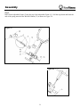
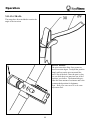
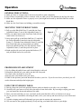
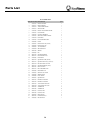
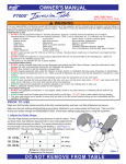
IT-2
Owner’s Manual
INVERSION TABLE
Customer Service
1.888.340.0482
Keys Fitness
4009 Distribution Drive
Suite 250
Garland, TX 75041
www.keysfitness.com
Read all precautions and instructions in this manual before using
this equipment.
215-00006
08/04
Table of Contents
Important Safety Information
3
Before You Start
4
Assembly
5-10
Operation
11-12
Exploded View
13
Parts List
14
Warranty
15
2
Important Safety Information
WARNING:
Before beginning this or any exercise program consult your physician. This is especially important for persons
over the age of 35 or persons with pre-existing health problems. Read all instructions in this manual before
using this product. Keys Fitness assumes no responsibility for personal injury or property damage sustained by
or through the use of this product.
1. Inspect and tighten all parts each time you use the unit. Replace any worn parts by contacting your local
dealer or Keys Fitness Customer Service at (888) 340-0482.
2. Keep your hands and other parts of your body away from moving parts other than designed handles.
3. Keep small children away from the unit at all times.
4. When adjusting the height make sure the pins are firmly in place. Failure secure the pins firmly may
result in injury.
5. If you feel pain or dizziness at any time while using this unit stop immediately and begin cooling down.
6. This unit a has maximum user capacity of 250 pounds.
3
Before You Start
Before use, read instruction manual completely.
It is extremely important to set the balance for your proper height and weight before use to avoid injury.
Remove footwear before use. (You could slip out of your shoes and cause injury.) Both feet must be placed in
the footrest.
First time users should have someone in attendance.
Keeps hands and finger clear from underneath sliding back rest to avoid injury.
Please consult your physician for any questions concerning health risks.
Keeps fingers clear of foot adjustment ratchet to avoid injury.
Caution is advised in certain medial pre-existing conditions.
Always consult your physician before starting regular use.
If you suffer from any of the following conditions do not use this equipment:
GLAUCOMA, DETACHED RETINA, CONJUNCTIVITIS, UNCONTROLLED HYPERTENSION (HIGH BLOOD PRESSURE),
IMPAIRED PULMONARY FUNCTIONS, ARRHYTHMIA, CAROTID ARTERY STENOSIS, SERVE VASCULAR DISEASE,
ANEURYSM, TENDENCY TOWARDS FAINTING OR DIZZY SPELLS, CEREBRAL SCLEROSIS, RECENT STROKE OR
TRANSIENT ISCHEMIC ATTACK, HISTORY OF BRAIN LESIONS, OTHER HEART OR CIRCULATORY DISORDERS FOR
WHICH YOU ARE BEING TREATED, SEVERE BACK PROBLEMS OR SPINAL INJURIES, BONE WEAKNESS (OSTEOPOROSIS), RECENT UNHEALED FRACTURES, MEDULLARY PINS, ARTIFICIAL HIP JOINTS OR OTHER ORTHOPEDIC
SUPPORTS SURGICALLY IMPLANTED, MIDDLE EAR INFECTION, RECENTLY HAD MAJOR SURGERY, USING SPECIAL MEDICATION, VENTRAL OR HIATAL HERNIA, TENDENCY TOWARDS BLEEDING, EXTREME OBESITY, INVERTAPHOBIA (FEAR OF INVERSION), AND PREGNANCY.
This is not a complete list. Should you have a condition or ailment that you think would restrict usage of this
unit, please consult a physician or therapist before continuing.
4
Assembly
Hardware
List
5
Assembly
6
Assembly
STEP 1
Spread the Front Support (1) and Rear
Support (2) of the base apart as shown
in Figure 1. Carefully push down on the
two folding arms until they are fully
lock in place.
Figure 1
Figure 2
STEP 2
Slide the Nylon Covers (28) onto the top
of the base assembly. The covers should
extend slightly below the Side Adjustable
Frame (2). Use the velcro straps to secure
them in place. (Figure 2)
7
Assembly
STEP 3
Slide the Adjustable Frame (3) into the tube of
the Main Frame (4). Set your desired height
using the Black Ball Pen (12) and secure in place
with the Knob Bolt 3/4” (14). (Figure 3)
Figure 3
Step 4
Insert the Foam Rod (9) through the holes at the
bottom of the Adjustable Frame (3). Use one Hex
Bolt M6*48mm (33), two Washers M6 (37), and
one Locknut M6 (39) to secure the rod in place.
Next, place one of the Roller Pads (40) into a
Foot Foam Brackets (10) and slide one onto each
end of the Foam Rod (9). Make sure the holes of
both the Foot Foam Bracket (10) and the Roller
Pads (40) line up together. Insert the Foot Frame
(6) into the Adjustable Frame (3) and secure in
place using Knob Bolt M8 (15). (Figure 4)
Figure 4
8
Assembly
Step 5
Insert Front Adjustable Frame (5) into the top of the Adjustable Frame (3). Pull the rope down and hook the
end of the spring onto the Hex Bolt M6*48mm (33) as shown in Figure 5b.
Figure 5a
Figure 5b
9
Assembly
Step 6
Slide a Pivot Arm (7) into each brace
located on the left and right side of the
Main Frame (4). Carefully set Unit A into
the notches at the top of Unit B. Connect
the Long Strap (30) to the Short Strap (29)
as shown in Figure 6b. Last, attach the
hook end of the Long Strap (30) to the
weld ring of the Front Support (1) and the
hook end of the Short Strap (29) to the
weld ring of the Main Frame (4). (Figure
6c)
Figure 6
Figure 6a
Figure 6b
Congratulations!
You have completed the assembly of the IT-2 Inversion Table.
10
Operation
NYLON STRAPS:
The straps have been included to restrict the
angle of the inversion.
PIVOT ARMS:
The pivot arms also allow for a greater or
lesser inversion degree. To adjust the position
simply pull out on the pivot arm until the
post is out of the hole. Once the post is clear
you can slide the pivot arms into one of the 3
positions you choose. The bottom hole provides the least amount of resistance and is the
recommended position for beginners.
Note: Both pivot arms must be in the same
adjustment hole.
11
Operation
GENERAL PRECAUTIONS:
1. Make sure there is enough room for the inversion table to rotate completely.
2. Keys Fitness recommends you have someone with you while you use the machine for the first few times.
3. Make sure the Adjustable Frame is properly set to your height and secured by the Black Ball Pen and the
Knob Bolt.
4. Make sure the Foot Frames are holding your ankles securely.
MOUNTING THE INVERSION TABLE:
1. Pull up on the Black Ball Pen (13) and slide the Front
Adjustable Frame (5) out of the Adjustable Frame (3).
2. Place you ankles between the Foot Form Pads (40) and
stand on the Foot Frame (6).
3. Once again, pull up on the Black Ball Pen (13) and slide
the Front Adjustable Frame back into the Adjustable
Frame (3). Push the Front Adjustable Frame (5) until the
Foot Form Pads (40) are snug around your ankles.
Release the Black Pall Ben (13) and adjust the Front
Adjustable Frame (5) until the pen locks in place.
4. Stand upright with your back against the Backrest (27)
and your hands lowered at your sides.
Figure 8
13
5
40
6
PROPER HEIGHT ADJUSTMENT
1. Set by sliding adjustable frame until desired height is achieved.
2. Mount the unit and lock your ankles into the foot form pads.
3. Lie back with your hands at your side.
4. Slowly place your hands across your chest.
5. While in this position your head should still be above your feet. If your feet are above your head, you will
need to dismount and adjust the height again.
USING THE INVERSION TABLE:
1. Start by lying with your back again the backrest with your hands at your side or on your thighs.
2. Carefully raise your arms to slowly allow the table to rotate backwards. By lowering or stoping your arms
you can control the downward rotation of the table.
3. Raise your arms until they are over your head. At this point the table will be as far back as it can go.
4. As you get more comfortable with using the table, move your arms up and down slowly to rock it back and
forth.
5. A gentle swinging motion will alternately put your spine in traction and compression.
6. You can return to the upright position by slowly moving your hands back down to your thighs.
12
Exploded View
13
Parts List
IT-2 PARTS LIST
REF# KEYS PART# DESCRIPTION
QTY.
1
223-00570
FRONT SUPPORT
2
223-00571
REAR SUPPORT
1
3
223-00572
ADJUSTABLE FRAME
1
4
223-00573
MAIN FRAME
1
5
219-00260
FRONT ADJUSTABLE FRAME
1
6
219-00261
FOOT FRAME
1
7
219-00262
CONNECT BUSHING
2
8
219-00263
SIDE ADJUSTABLE FRAME
2
9
219-00264
FOAM ROD
1
10
219-00265
FOOT FORM BRACKET
4
11
210-00080
HOOK
2
12
210-00081
BLACK BALL PIN (LONG)
1
13
210-00082
BLACK BALL PIN
1
14
210-00083
3/8" KNOB BOLT
1
15
210-00084
M8 KNOB BOLT
1
16
202-00100
SPRING
1
17
210-00085
PIN
1
18
206-00120
SQUARE BUMPER
1
19
206-00121
FOOT FRAME PLUG
2
20
210-00086
HAND GRIP
2
21
206-00122
SQUARE SPACER (50*205)
1
22
206-00123
SQUARE END PLUG (33.4X33.4)
2
23
206-00124
ROUND END PLUG 22mm
2
24
206-00125
SQUARE BUSHING (50*38)
1
25
206-00126
END CAP 22mm
2
26
206-00127
PIECE BUMPER 22mm
2
27
228-00080
BACKREST PAD
1
28
210-00087
SIDE NYLON COVER
2
29
210-00088
SHORT STRAP
1
30
210-00089
LONG STRAP
1
31
228-00081
SQUARE PAD
1
32
202-00101
HEX BOLT M8*25mm
2
33
202-00102
HEX BOLT M6*28mm
2
34
202-00103
ALLEN BOLT M6*45mm
4
35
202-00104
ALLEN BOLT M6*15mm
1
36
202-00105
WASHER M8
4
37
202-00106
WASHER M6
12
38
202-00107
LOCKNUT M8
2
39
202-00108
LOCKNUT M6
6
40
228-00082
ROLLER PAD
4
41
206-00128
DOME END PLUG
4
42
210-00090
ROUND PIECE
1
14
1
Warranty Information
KEYS FITNESS PRODUCTS, LP LIMITED WARRANTY
PRODUCT:
HOME USE WARRANTY:
IT-2
5 Years Parts
This Limited Warranty applies in the United States and Canada to products manufactured or distributed by Keys Fitness Products,
LP (“Keys”) under the KEYS brand name. The warranty period to the original purchaser is listed above in the table.
Keys warrants that the Product you have purchased for use from Keys or from an authorized Keys reseller is free from defects in
materials or workmanship under normal use during the warranty period. Your sales receipt, showing the date of purchase of the
Product, is your proof of purchase. This warranty only extends to you, the original purchaser. It is not transferable to anyone who
subsequently purchases the Product from you. It excludes expendable parts (wear items). Wear items pertain to components that might
need to be replaced due to normal wear and tear. These items vary per product but will include computer overlays, pedal straps, rope
cords, seats, grips, chains, bottom bracket assemblies, pads, upholstery, pulleys, bearings, etc. Please contact a Keys Fitness customer service representative for specifics on wear items. This Limited Warranty becomes VALID ONLY if the product is purchased
through a Keys Fitness authorized dealer unless otherwise authorized by Keys Fitness in writing.
During the warranty period Keys will repair or replace (at Keys' option) the product if it becomes defective, malfunctions, or otherwise fails to conform with this Limited Warranty under normal use. In repairing the Product, Keys may replace defective parts, or at
the option of Keys, serviceable used parts that are equivalent to new parts in performance. All exchanged parts and Products
replaced under this warranty will become the property of Keys. Keys reserves the right to change manufacturers of any part to cover
any existing warranty.
This warranty DOES NOT COVER shipping charges, export taxes, custom duties and taxes, or any other charges associated with
transportation of the parts or Product.
To obtain warranty service, you must contact a Keys authorized retailer, service technician or Keys Fitness at our phone numbers
located in this manual. Any parts determined to be defective must be returned to Keys to obtain warranty service. You must prepay
any shipping charges, export taxes, custom duties and taxes, or any other charges associated with transportation of the parts or
Product. In addition, you are responsible for insuring any parts or Product shipped or returned. You assume the risk of loss during
shipment. You must present Keys with proof-of-purchase documents (including the date of purchase). Any evidence of alteration,
erasing or forgery of proof-of-purchase documents will be cause to void this Limited Warranty.
This warranty does not extend to any product not purchased from Keys or from an authorized Keys reseller. This Limited Warranty
does not extend to any Product that has been damaged or rendered defective; (a) as a result of accident, misuse, or abuse; (b) by the
use of parts not manufactured or sold by Keys; (c) by modification of the Product or normal wear and tear; (d) operation on incorrect
power supplies; or (e) as a result of service by anyone other than Keys, or an authorized Keys warranty service provider. Product on
which the serial number has been defaced or removed is not eligible for warranty service. Should any Product submitted for warranty service be found ineligible, an estimate of repair cost will be furnished and the repair will be made if requested by you upon Keys'
receipt of payment or acceptable arrangements for payment.
EXCEPT AS EXPRESSLY SET FORTH IN THIS WARRANTY, KEYS MAKES NO OTHER WARRANTIES, EXPRESSED OR
IMPLIED, INCLUDING ANY IMPLIED WARRANTIES OF MERCHANTABILITY AND FITNESS FOR A PARTICULAR PURPOSE. KEYS EXPRESSLY DISCLAIMS ALL WARRANTIES NOT STATED IN THIS LIMITED WARRANTY. ANY IMPLIED
WARRANTIES THAT MAY BE IMPOSED BY LAW ARE LIMITED TO THE TERMS OF THIS LIMITED WARRANTY. NEITHER KEYS NOR ANY OF ITS AFFILIATES SHALL BE RESPONSIBLE FOR INCIDENTAL OR CONSEQUENTIAL DAMAGES. SOME STATES DO NOT ALLOW LIMITATIONS ON HOW LONG AN IMPLIED WARRANTY LASTS OR THE
EXCLUSION OR LIMITATION OF INCIDENTAL OR CONSEQUENTIAL DAMAGES, SO THE ABOVE LIMITATIONS OR
EXCLUSION MAY NOT APPLY TO YOU. This Limited Warranty gives you specific legal rights and you may also have other
rights that may vary from state to state. This is the only express warranty applicable to Keys-branded products. Keys neither
assumes nor authorizes anyone to assume for it any other express warranty.
PLEASE SEND IN THE WARRANTY CARD WITHIN TEN (10) DAYS OF PURCHASE TO REGISTER YOUR UNIT WITH
KEYS FITNESS PRODUCTS, LP.
MAIL WARRANTY CARD TO:
KEYS FITNESS PRODUCTS, PO BOX 551239, DALLAS, TX 75355
15
Customer Service
1.888.340.0482
Keys Fitness
4009 Distribution Drive
Suite 250
Garland, TX 75041
www.keysfitness.com