1
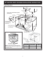
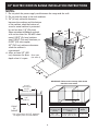
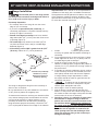
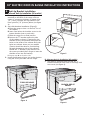
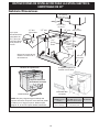
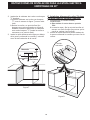
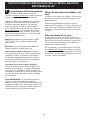
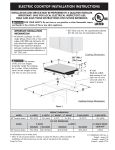
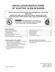
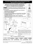
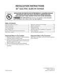
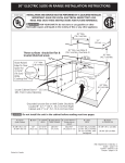
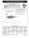
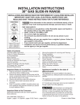
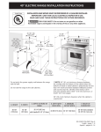
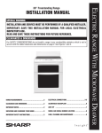
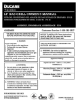
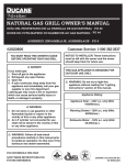
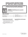
INSTALLATION INSTRUCTIONS
30" ELECTRIC DROP-IN RANGE
INSTALLATION AND SERVICE MUST BE PERFORMED BY A QUALIFIED INSTALLER.
IMPORTANT: SAVE FOR LOCAL ELECTRICAL INSPECTOR'S USE.
READ AND SAVE THESE INSTRUCTIONS FOR FUTURE REFERENCE.
United States
FOR YOUR SAFETY: Do not store or use gasoline
or other flammable vapors and liquids in the vicinity of this or
any other appliance.
Table of Contents
Important Safety Instructions .........................................2
Cutout Dimensions .......................................................3-4
Electrical Requirements...................................................5
Electrical Connection .................................................. 5-6
Serial Plate Location .......................................................6
Range Installation ............................................................7
Anti-tip Bracket Installation........................................8-9
Check Operation ........................................................... 10
Model and Serial Number Location ........................... 10
Before you call for Service ........................................... 10
Important Notes to the Installer
Important Note to the Consumer
1. Read all instructions contained in these
installation instructions before installing range.
2. Remove all packing material from the oven and
the drawer compartments before connecting the
electrical supply to the range.
3. Observe all governing codes and ordinances.
4. Be sure to leave these instructions with the
consumer.
Printed in Canada
Keep these instructions with your owner's guide for
future reference.
P/N 318201628 (1209) Rev. B
English – pages 1-10
Español – páginas 11-20
30" ELECTRIC DROP-IN RANGE INSTALLATION INSTRUCTIONS
IMPORTANT SAFETY INSTRUCTIONS
This manual contains important safety symbols and instructions. Please pay attention to these symbols and
follow all instructions given.
This symbol will help alert you to situations that may cause serious bodily harm, death or
property damage.
This symbol will help alert you to situations that may cause bodily injury or property
damage.
• Be sure your range is installed and grounded
reduce by installing a range hood that project
properly by a qualified installer or ser vice
horizontally a minimum of 5 inches beyond the
technician.
bottom of the cabinet.
• This range must be electrically grounded in
• Do not use the oven as a storage space. This
accordance with local codes or, in their absence,
creates a potentially hazardous situation.
with the National Electrical Code ANSI/NFPA
• Never use your range for warming or heating
No. 70—latest edition.
the room. Prolonged use of the range without
• The installation of appliances designed for
adequate ventilation can be dangerous.
manufactured (mobile) home installation must
• Do not store or use gasoline or other flammable
conform with Manufactured Home Construction
vapors and liquids near this or any other
and Safety Standard, title 24CFR, part 3280
appliance. Explosions or fires could result.
[Formerly the Federal Standard for Mobile Home
• Reset all controls to the "off" position after using
Construction and Safety, title 24, HUD (part
a programmable timing operation.
280)] or when such standard is not applicable,
FOR MODELS WITH SELF-CLEAN FEATURE:
the Standard for Manufactured Home Installation
• Remove broiler pan, food and other utensils before
1982 (Manufactured Home Sites, Communities
self-cleaning the oven. Wipe up excess spillage.
and Setups), ANSI Z225.1/NFPA 501A-latest
Follow the pre cleaning instructions in the Use and
edition, or with local codes.
Care Guide.
• Make sure the wall coverings around the range
can withstand the heat generated by the range.
Tip Over Hazard
• Before installing the range in an area covered with
• A child or adult can tip the
linoleum or any other synthetic floor covering,
range and be killed.
make sure the floor covering can withstand heat
•
Verify the rear bracket is
at least 90°F above room temperature without
engaged with countertop or
shrinking, warping or discoloring. Do not install
the anti-tip device has been
the range over carpeting unless you place an
installed to the walls of the
insulating pad or sheet of 1/4" thick plywood
cabinet as per installation instructions.
between the range and carpeting.
• Ensure the anti-tip bracket is re-engaged with
the countertop or to the cabinet side walls as
Never leave children alone or
per the installation instructions when the range
unattended in the area where an appliance is in
is moved.
use. As children grow, teach them the proper, safe
• Do not operate the range without the anti-tip
use of all appliances. Never leave the oven door
device in place and engaged.
open when the range is unattended.
• Failure to follow these instructions can result in
death or serious burns to children and adults.
Stepping, leaning or sitting on the
door of this range can result in serious injuries and
can also cause damage to the range.
To check if the anti-tip bracket is
installed properly, use both arms
• Do not store items of interest to children in the
and grasp the rear edge of range
cabinets above the range. Children could be seriously
back. Carefully attempt to tilt range
burned climbing on the range to reach items.
forward. When properly installed,
• To eliminate the risk of burns or fire by reaching
the range should not tilt forward.
over heated surface units, cabinet storage space
Refer to the anti-tip bracket installation instructions
above the surface unit should be avoided. If
supplied with your range for proper installation.
cabinet storage is to be provided the risk can be
2
30" ELECTRIC DROP-IN RANGE INSTALLATION INSTRUCTIONS
Cutout Dimensions
30"
(76.2cm)
30" Min.
(76.2 cm Min.)
See Note 3
These surfaces should be flat & leveled
(hatched area).
18" Min.
1/4” min. (45.7 cm Min.)
1/2” min.
1½" Max.
(3.8 cm) Max.
A
Shave Raised Edge
to Clear Space for a
31½" (81 cm) Wide
Cooktop Rim.
31½"
(81 cm)
Exact
C
1/2” min.
App. 1-7/8"
(4.8 cm)
Locate Cabinet Doors
1" (2.5 cm) Min. from
Cutout Opening
24" Min.
(61 cm Min.)
Grounded Junction Box in
adjoining Cabinet
Smoothtop Models
.
" Min
27½
Front Filler
Support
ANTI-TIP BRACKET
AT REAR OF RANGE
Front Cabinet Filler
(If required)
48" (122 cm)
Armored Cable
NOTE: Two sets of holes are provided under antitip bracket. Bracket is attached in the upper hole
position at the factory. Refer also to page 6, item 9
for additional details.
A. Cutout Width
(Countertop and
cabinet)
30 ± 1/16"
(76.2 ± 0.15 cm)
3
B. Cutout Depth
C. Height of
(According to front of
Cutout
cabinet) *see next page
21 3/4" (55.2 cm) min 29" (73.7 cm)
22 1/8" (56.2 cm) max
30" ELECTRIC DROP-IN RANGE INSTALLATION INSTRUCTIONS
NOTES:
1. Do not pinch the power supply cord between the range and the wall.
2. Do not seal the range to the side cabinets.
3. 24" (61 cm) minimum clearance
between the cooktop and the bottom
of the cabinet when the bottom of
wood or metal cabinet is protected
by not less than 1/4" (0.64 cm)
flame retardant millboard covered
with not less than No. 28 MSG sheet
metal, 0.015" (0.4 mm) stainless
steel, 0.024" (0.6 mm) aluminum, or
0.020" (0.5 mm) copper.
30" (76.2 cm) minimum clearance
when the cabinet is
unprotected.
4. Allow at least 20" (50.1
cm) clearance for door Door open
(see note 4)
depth when it is open.
IMPORTANT: Cabinet and countertop width should
match the cutout width.
22 7/8"*
(58.1 cm) min.
23 1/4"*
(59.05 cm) max.
A
1 1/8"
(2.86 cm)
FRONT
OF
CABINET
A
BRef.
A. Cutout Width
(Countertop and
cabinet)
30 ± 1/16"
(76.2 ± 0.15 cm)
* For cutouts below 22 7/8", appliance
will slightly show out of the cabinet.
4
B. Cutout Depth
(According to front of
cabinet)
21 3/4" (55.2 cm) min
22 1/8" (56.2 cm) max
C. Height of
Cutout
29" (73.7 cm)
30" ELECTRIC DROP-IN RANGE INSTALLATION INSTRUCTIONS
1 Electrical Requirements
This appliance must be supplied with the proper voltage
and frequency, and connected to an individual, properly
grounded branch circuit, protected by a circuit breaker
or fuse 40A or 50A.
Electrical Shock Hazard
• Electrical ground is required on this appliance.
• Do not connect to the electrical supply until
appliance is permanently grounded.
• Disconnect power to the junction box before making
the electrical connection.
• This appliance must be connected to a grounded,
metallic, permanent wiring system, or a grounding
connector should be connected to the grounding
terminal or wire lead on the appliance.
• Do not use a gas supply line for grounding the
appliance.
Observe all governing codes and local ordinances
1. A 3-wire or 4-wire single phase 120/240 or 120/208
Volt, 60 Hz AC only electrical supply is required on
a separate circuit fused on both sides of the line (red
and black wires). A time-delay fuse or circuit breaker
is recommended. DO NOT fuse neutral (white wire).
NOTE: Wire sizes and connections must conform with
the fuse size and rating of the appliance in accordance
with the American National Electrical Code ANSI/NFPA
No. 70-latest edition, or with Canadian CSA Standard
C22.1, Canadian Electrical Code, Part 1, and local codes
and ordinances.
Failure to do any of the above could result in a fire,
personal injury or electrical shock.
In cold weather shipping and storage
conditions, make sure that oven is in final location
at least three (3) hours before switching on power.
Switching on power while oven is still cold may damage
the oven controls.
An extension cord should not be used
with this appliance. Such use may result in a fire,
electrical shock, or other personal injury. If you need a
longer power cord you can purchase a 10' (3 m) power
cord kit #903056-9010 by calling the Service Center.
2 Electrical connection
It is the responsibility and obligation of the consumer to
contact a qualified installer to assure that the electrical
installation is adequate and is in conformance with
the National Electrical Code ANSI/NFPA No. 70latest edition, or with CSA Standard C22.1, Canadian
Electrical Code, Part 1, and local codes and ordinances.
2. These appliances should be connected to the fused
disconnect (or circuit breaker) box through flexible
armored or nonmetallic sheathed cable. The flexible
armored cable extending from the appliance should
be connected directly to the junction box. The
junction box should be located as shown in Figure
1 or Figure 2 and with as much slack as possible
remaining in the cable between the box and the
appliance, so it can be moved if servicing is ever
necessary.
3. A suitable strain relief must be provided to attach
the flexible armored cable to the junction box.
Risk of electrical shock (Failure to
heed this warning may result in electrocution or
other serious injury.) This appliance is equipped with
copper lead wire. If connection is made to aluminum
house wiring, use only connectors that are approved
for joining copper and aluminum wire in accordance
with the National Electrical Code and local code and
ordinances. When installing connectors having screws
which bear directly on the steel and/or aluminum
flexible conduit, do no tighten screws sufficiently to
damage the flexible conduit. Do not over bend or
excessively distort flexible conduit to avoid separation
of convolutions en exposure of internal wires.
DO NOT ground to a gas supply pipe. DO NOT
connect to electrical power supply until appliance is
permanently grounded. Connect the ground wire before
turning on the power.
5
30" ELECTRIC DROP-IN RANGE INSTALLATION INSTRUCTIONS
If oven is used in a new branch circuit installation
(1996 NEC), mobile home, recreational vehicle, or
where local codes DO NOT permit grounding through
the neutral (white) wire, the appliance frame MUST
NOT be connected to the neutral wire of the 4-wire
electrical system. (see figure 2):
1. Disconnect the power supply.
2. Separate the green (or bare copper) and white
appliance cable wires.
3. In the junction box:
Connect appliance and power supply cable wires as
shown in Figure 2.
(If your appliance is equipped with a
white neutral conductor.)
This appliance is manufactured with a white neutral
power supply and a frame connected copper wire.
The frame is grounded by connection of grounding
lead to neutral lead at the termination of the conduit,
if used in USA, in a new branch circuit installation
(1996 NEC), mobile home, recreational vehicles, where
local code do not permit grounding trough the neutral
(white) wire or in Canada, disconnect the white and
green lead from each other and use ground lead to
ground unit in accordance with local codes, connect
neutral lead to branch circuit-neutral conductor in
usual manner see Figure 4. If your appliance is to
be connected to a 3 wire grounded junction box
(US only), where local code permit connecting the
appliance-grounding conductor to the neutral (white)
see Figure 3.
Cable from Power Supply
Ground Wire
Black
Wires
NOTE TO ELECTRICIAN: The armored cable leads
supplied with the appliance are UL-recognized for
connection to larger gauge household wiring. The
insulation of the leads is rated at temperatures much
higher than temperature rating of household wiring. The
current carrying capacity of the conductor is governed
by the temperature rating of the insulation around the
wire, rather than the wire gauge alone.
Ground Wire
(Bare or Green
Wire)
Junction Box
White Wire
U.L.-Listed Conduit
Connector (or CSA
listed)
Cable from appliance
Figure 2
4-WIRE GROUNDED JUNCTION BOX
Where local codes permit connecting the appliancegrounding conductor to the neutral (white) wire (US
Only) (see figure 1):
1. Disconnect the power supply.
2. In the junction box:
connect appliance and power supply cable wires as
shown in Figure 1.
Serial Plate Location
You will find the model and serial number printed on the
serial plate. The serial plate is located as shown.
Remember to record the serial number for future
reference.
Cable from Power Supply
Black
Wires
White Wire
(Neutral)
White Wire
Red
Wires
Red
Wires
Junction
Box
White Wire
(Neutral)
Ground Wire
(Bare or Green Wire)
U.L.-Listed Conduit
Connector (or CSA listed)
Cable from appliance
Figure 1
3-WIRE GROUNDED JUNCTION BOX
6
30" ELECTRIC DROP-IN RANGE INSTALLATION INSTRUCTIONS
Important Note: Door removal is not a requirement for
installation of the range, but is an added convenience.
The appliance should be placed on a table or the front
of the appliance should be raised to be able to fully
open the door. Please refer to the Use and Care Guide
for oven door removal instructions.
3 Range Installation
The electrical power to the range must be
shut off while line connections are being made. Failure to
do so could result in serious injury or death.
Countertop Preparation
• The cooktop sides of the range fit over the cutout
edge of your countertop.
• If you have a square finish (flat) countertop, no
countertop preparation is required. Cooktop sides lay
directly on edge of countertop.
• Formed front-edged countertops must have molded
edge shaved flat 3/4" (1.9 cm) from each front corner
of opening (Figure 3).
• Tile countertops may need trim cut back 3/4"(1.9
cm) from each front corner and/or rounded edge
flattened (Figure 3).
• If the existing cutout width is greater than 30 1/16"
(76.4 cm), reduce the ¾" (1.9 cm) dimension.
1.
¾”
(1.9 cm)
Min.
Cutout
Width
2.
3.
31½”
(81 cm)
4.
Formed or tile countertop
trimmed ¾" (1.9 cm)
back at front corners of
countertop opening.
¾”
(1.9 cm)
Figure 3
5.
This range is designed to hang from the countertop. It
does not rest on the floor.
6.
7.
Be sure the bottom of any wall cabinets are a minimum
of 30" (76.2 cm) above the rangetop area.
To eliminate the hazard or reaching over heated surface
units, cabinet storage space located above the surface
units should be avoided. If cabinet storage is to be
provided, the hazard can be reduced by installing a
range hood that projects horizontally a minimum of 5"
(12.7 cm) beyond the bottom front edge of the cabinets.
8.
7
Install base cabinets 30" (76.2cm) apart, and be
sure they are plumb and level before attaching to
countertop.
Cut countertop exactly as shown in Figure 1. Shave
raised edge level to clear 31 1/2" (81cm) wide rim
on rolled edge styled countertops.
Install the wiring junction box in an adjoining
cabinet or under the floor (range has 48"/122cm of
conduit). Cut 1-1/4" (3.2cm) hole to bring conduit to
the junction box.
To provide an optimum installation, the top surface
of the countertop must be level and flat (lie on the
same plane) around the 3 sides that are adjacent
to range cooktop. Proper adjustments to make
the top flat should be made or gaps between the
countertop may occur.
To reduce the risk of damaging your
appliance, do not handle or manipulate it by the
ceramic glass. Manipulate with care.
Move range in front of cabinet opening.
Push the electric conduit through the hole and
attach it to the junction box. Leave enough slack in
the conduit to allow the range to be pulled forward
several inches for service if necessary.
Oven door is heavy. It is advisable to remove door
and eliminate its weight as range is lifted into
position. See oven door removal instructions in the
Use and Care Guide. NEVER lift the appliance by
the control panel doing so may damage the control
panel. Lift the range into position on the countertop
and make sure the appliance is centered in the
cutout opening to be sure that the flanges of the
upper side panel are sitting on the countertop to
avoid glass breakage.
30" ELECTRIC DROP-IN RANGE INSTALLATION INSTRUCTIONS
4 Anti-tip Bracket installation
A. Preferred Anti-tip installation (All models)
1. The range is equipped with an anti-tip bracket
attached to the back of the range with two
screws. If countertop thickness is greater than
1/2" (1.3cm), relocate anti-tip bracket to the
lower position 1/4" (6.4 mm) below (see figure
4).
2. Anti-slide brackets Installation (Figure 5):
A.Place the range so that it is about 6" out of
the cabinet.
B. Insert from below the shoulder screws in the
bottom bracket (one on each side)
C. Slide the range into its final position.
D. Position the "L" bracket against the side
of the cabinet so that it is retained by the
shoulder screws, hold bracket and mark the
holes on the inside of the cabinet. Drill pilot
holes into cabinet where you just marked
(Caution should be taken to avoid drilling
through the opposite side of the cabinet).
Attach the "L" bracket to the cabinet with
the screws provided (don't forget to insert the
shoulder screw into the bracket).
Figure 5
E. Repeat steps D on the other side.
3. Install the decorative lower trim under the door
using the screws provided with the range.
B. Alternate Anti tip installation (All models)
1. The range is equipped with two anti-tip "L"
brackets located on each side of the range with
two screws (see figure 6).
ANTI-TIP BRACKET
AT REAR OF RANGE
ANTI-TIP "L" BRACKET
ON EACH SIDE OF
RANGE
Figure 4
Figure 6
8
30" ELECTRIC DROP-IN RANGE INSTALLATION INSTRUCTIONS
2. Anti-Tip cabinet "L" brackets Installation:
A.Install the anti-tip cabinet "L" brackets as
shown on Figure 7, one on each side.
B. Slide the range into its final position. (The
anti-tip L brackets attached to the range
should be located under the anti-tip cabinet
L brackets when the range is at its final
position.)
3. Install the decorative lower trim under the door
using the screws provided with the range.
C. Alternate Anti tip installation (Model with liftup cooktop only)
1. Anti-tip/anti-slide screws installation:
A. Slide the range to its final position.
B. Lift the cooktop and secure range burner box
to cabinet with screws supplied to prevent
range from tipping (Figure 8).
2. Install the decorative lower trim under the door
using the screws provided with the range.
Anti-Tip
mounting
screws 2 on
each side
Counter
6¼"
CL
20"
Anti-tip "L"
bracket
CL
Figure 7
Figure 8
9
30" ELECTRIC DROP-IN RANGE INSTALLATION INSTRUCTIONS
5 Checking Operation
Model and Serial Number Location
Some models have manual controls. Refer to the
Owner's Guide and check all controls for correct
operation.
The serial plate is located along the side of the
oven door in the open position.
When ordering parts for or making inquires about
your oven, always be sure to include the model and
serial numbers and a lot number or letter from the
serial plate on your oven.
Some models are equipped with an electronic oven
control. Each of the functions has been factory
checked before shipping. However, it is suggested
that you verify the operation of the electronic oven
controls once more. Refer to the Owner's Guide
for operation. Follow the instructions for the Clock,
Timer, Bake, Broil, Convection (some models) and
Clean (some models) functions.
Before You Call for Service
Read the Avoid Service Checklist and operating
instructions in your Owner's Guide. It may save
you time and expense. The list includes common
occurrences that are not the result of defective
workmanship or materials in this appliance.
Bake–After setting the oven to 350°F (177°C)
for baking, the lower element in the oven should
become red.
Refer to the warranty in your Owner's Guide for
our toll-free service number and address. Please
call or write if you have inquiries about your
product and/or need to order parts.
Broil–When the oven is set to BROIL, the upper
element in the oven should become red.
Clean (some models)–When the oven is set for
a self-cleaning cycle, the upper element should
become red during the preheat portion of the
cycle. After reaching the self-cleaning temperature,
the lower element will become red.
Convection (some models)–When the oven is set
for convection baking or roasting, both elements
cycle on and off alternately and the convection fan
will turn. The convection fan will stop turning when
the oven door is opened during convection baking
or roasting.
IMPORTANT NOTE: A fan inside the upper rear
part above the oven (some models) provides
additional cooling of the oven electrical and
electronic components. The fan will continue to
run after the oven has been operating at high
temperatures.
10
INSTRUCCIONES DE INSTALACIÓN
ESTUFA ELÉCTRICA EMPOTRABLE DE 30"
LA INSTALACIÓN Y EL SERVICIO DEBEN SER EFECTUADOS POR UN INSTALADOR
CALIFICADO.
IMPORTANTE: GUARDE ESTAS INSTRUCCIONES PARA USO DEL INSPECTOR LOCAL DE
ELECTRICIDAD. LEA Y GUARDE ESTAS INSTRUCCIONES PARA REFERENCIA FUTURA.
Estados Unidos
PARA SU SEGURIDAD: No almacene ni utilice gasolina
u otros vapores y líquidos inflamables en la proximidad de este o de
cualquier otro artefacto.
Tabla de materias
Importante instrucciones de seguridad ......................12
Gabinete dimensiones .............................................13-14
Requerimientos eléctricos ............................................. 15
Conexión eléctrica....................................................15-16
Ubicación de la placa de serie ...................................16
Conexión eléctrica a la cocina.............................. 21-22
Instalación de la estufa ................................................17
Instrucciones de instalación de la
fijación anti-inclinación ...........................................18-19
Comprobación del funcionamiento ........................... 20
Ubicación del numero de modelo y de serie ........... 20
Antes de llamar al servicio ......................................... 20
Notas importantes para el
instalador
Nota importante para el
consumidor
1. Lea todas las instrucciones antes de instalar la
cocina.
2. Retire todo material de empaquetado del horno
y de la gaveta de entibiado antes de conectar el
suministro eléctrico a la cocina.
3. Observe todo código o reglamento.
4. Asegúrese de dejar estas instrucciones con el
consumidor
Impreso en Canada
Mantenga estas instrucciones con el manual del
usuario para futuras referencias.
P/N 318201628 (1209) Rev. B
English – pages 1-10
Español – páginas 11-20
INSTRUCCIONES DE INSTALACIÓN PARA LA ESTUFA ELÉCTRICA
EMPOTRABLE DE 30"
IMPORTANTES INSTRUCCIONES DE SEGURIDAD
Este manual contiene importantes mensajes de seguridad. Siempre lea y obedezca todo mensaje de seguridad.
Indica una situación muy peligrosa, la cual de no ser evitada puede ocasionar graves heridas y
hasta la muerte.
ATENCION Indica una situación de peligro inminente, la cual de no ser evitada puede ocasionar
heridas leves o daños al producto solamente.
• Asegúrese que su cocina está instalada y
conectada adecuadamente a tierra por un
instalador calificado o un técnico de servicio.
• Esta cocina debe ser conectada a tierra
eléctricamente de acuerdo con los códigos
locales, o de no existir, con la National Electrical
Code ANSI/NFPA No.70- última edición.
• La instalación de electrodomésticos destinados
para casas (movibles) deben conformarse
con la Manufactured Home Construction and
Safety Standard, título 24CFR, parte 3280
[antiguamente la Federal Standard for Mobile
Home Construction and Safety, título 24, HUD
(parte 280)] o cuando este código no se aplica,
la Standard for Manufactured Home Installation
1982 (Manufactured Home sites, communities and
setups) ; ANSIZ225.1/NFPA 501A- última edición
o con códigos locales.
• A s e g ú re s e q u e e l e m p a p e l a d o d e p a re d
alrededor de la cocina pueda resistir el calor
generado por la cocina.
• Antes de instalar la cocina en una área cubierta
de linóleo o cualquier otro revestidos de piso
sintético, asegúrese que éste pueda resistir al
menos 90°F sobre la temperatura de la pieza sin
encogerse, ladearse o descolorareis. No instale
la cocina encima de una alfombra a menos
que coloque una placa de aislamiento o una
plancha de 1/4" de madera entre la cocina y el
alfombrado.
Nunca deje a los niños
solos o sin cuidado en el area donde el
electrodoméstico etá en uso. A medida que los
niños crezcan, enséñeles el uso adecuado de los
electrodomésticos. Nunca deje la puerta del horno
abierta cuando la cocina esté sin supervisión.
Pisar, apoyarse o sentarse en
las puertas o los cajones de la cocina pueden
causar graves heridas y también dañar la cocina.
• No coloque cosas que atraigan a los niños
sobre los gabinetes encima de la cocina. Los
niños podrían sufrir quemaduras tratando de
alcanzarlos.
• Para evitar riesgos de quemaduras o incendios
al tocar superficies calientes, se deben evitar los
armarios sobre la superficie de los quemadores.
Si existe un armario, se pueden reducir los
•
•
•
•
riesgos instalando una campana que se extienda
horizontalmente en un mínimo de 5" por sobre la
parte inferior de los armarios.
No use el horno como espacio de almacenamiento.
Esto crea una situación muy peligrosa.
Nunca use su cocina para calentar la pieza.
El uso prolongado de la cocina sin ventilación
adecuada puede ser peligroso.
No guarde o use gasolina u otros vapores
inflamables y líquidos cerca de éste o cualquier
otro electrodoméstico. Esto podría causar una
explosión o un incendio.
Vuelva a programar todos los controles a la
posición “off” (apagado) después de haber
utilizado el conteo contador automático.
PARA LOS MODELOS CON AUTO-LIMPIEZA:
• Retire el rostisador, la comida y otros utensilios
antes de auto-limpiar el horno. Limpie todo
exceso de derrames. Siga las instrucciones para
la pre-limpieza en el Manual del usuario.
Riesgo de volcamiento
• Un niño o adulto puede volcar la
estufa y acabar muerto.
• Verificar que el braquet trasero
este calibrado con la cubierta o
el utensilio del anti-vuelco sea
instalado en las paredes del cabinete como la
indican las instrucciones.
• Asegurar que el braquet antivuelco sea calibrado con
la cubierta o los lados de la cabina así como lo indican
las instrucciones cuando la estufa sea movida.
• No utilice la estufa sin el dispositivo antivuelco
instalado y acoplado.
• Si no se siguen estas instrucciones, se puede provocar
la muerte o quemaduras graves en niños y adultos.
Para verificar si la fijaciones de antiinclinación está instalado correctamente,
sostenga el borde trasero de la parte
trasera de la estufa usando ambos brazos.
Intente inclinar la estufa hacia adelante con cuidado.
Si está instalada correctamente, la estufa no debería
inclinarse hacia adelante.
Consulte las instrucciones de instalación del soporte
antivuelco proporcionadas con la estufa para instalarlo
adecuadamente.
12
INSTRUCCIONES DE INSTALACIÓN PARA LA ESTUFA ELÉCTRICA
EMPOTRABLE DE 30"
Gabinete Dimensiones
30" (76.2cm)
30" Mín.
(76,2 cm Mín.)
Vea Note 3
Lije la parte
elevade del borde
para obtener las
31½" (81 cm) de
ancho del reborde
de la plancha de
cocinar.
1½" Máx.
(3,8 cm) Máx.
18" Mín.
1/4” min. (45,7 cm Mín.)
1/2” min.
A
31½"
(81 cm)
Exacto
1/2” min.
C
App. 1-7/8"
(4,8 cm)
Ubique las puertas de los
armarios un mínimo de 1"
de la abertura.
24" Mín.
(61 cm Mín.)
Modelos de superficie lisa
La caja de empalmes de
conexión con la tierra.
27½"
Min.
Soporte Antivuelco
al Fondo de la Estufa
Front Filler
Support
Front Cabinet Filler
(If required)
Cable Blindado
A. Anchura de
B. Profundidad de
C. Altura
recortado (encima y recortado (Según parte del armario
armario)
delantera del armario)
NOTA: Hay dos juegos de agujeros debajo del
soporte antivuelco. El soporte viene colocado, desde
la fábrica, en el agujero superior. Refiérase para
paginar 14, el artículo 9 para detalles adicionales.
30 ± 1/16"
(76.2 ± 0.15cm)
13
21 3/4" (55.2cm) min 22
1/8" (56.2cm) max
29" (73.7cm)
INSTRUCCIONES DE INSTALACIÓN PARA LA ESTUFA ELÉCTRICA
EMPOTRABLE DE 30"
NOTAS:
1. No pellizque el cordón eléctrico entre la estufa y la pared.
2. No selle la estufa a los armarios de lado.
3. Un espacio mínimo de 24" (61 cm)
entre la superficie de la estufa y el
fondo del armario cuando el fondo
del armario de madera o metal
está protegido por no menos de
1/4" (0.64 cm) de madera resistente
al fuego cubierta por una lámina
metálica de MSG, número 28, 0.015"
(0.4 mm) de acero inoxidable,
0.024" (0.6 mm) de aluminio, o 0.02"
(0.5 mm) de cobre.
Un espacio mínimo
de 30" (76.2 cm)
cuando el armario
no está protegido.
4. Deje por los 20"
(50.1 cm) de
espacio libre para
la profundidad de
la puerta cuando
esta abierta.
Puerta abierta
(vea la nota 4)
IMPORTANTE: El ancho de la cubierta y el armario
debe de ser igual al ancho del corte.
22 7/8"*
(58.1 cm) min.
23 1/4"*
(59.05 cm) max.
EA
1 1/8"
(2.86 cm)
PARTE
DELANTERA
DEL
ARMARIO
EA
BRef.
* Para los recortados menos que 22 7/8’’, el
electrodoméstico aparecería ligeramente en el exterior
del armario.
14
A. Anchura de
recortado (encima
y armario)
B. Profundidad de
recortado (Según parte
delantera del armario)
C. Altura del
armario
30 ± 1/16"
(76.2 ± 0.15cm)
21 3/4" (55.2cm) min
22 1/8" (56.2cm) max
29" (73.7cm)
INSTRUCCIONES DE INSTALACIÓN PARA LA ESTUFA ELÉCTRICA
EMPOTRABLE DE 30"
1 Requerimientos Eléctricos
Se debe proveer el voltaje y la frecuencia apropiados a
este electrodoméstico, y conectarse a un circuito individual
correctamente puesto a tierra, protegido por un interruptor
o un fusible de 40A o 50A
Riesgo de choque eléctrico
• Una puesta a tierra se requiere en este aparato.
• No lo conecte a la corriente eléctrica hasta que el
aparato haya sido puesto a tierra.
• Desconecte la corriente eléctrica a la caja de
empalmes antes de hacer la conexión eléctrica.
• Este aparato debe estar conectado con un
sistema de alambres puesto en tierra, metálico
y permanente o un conector de puesta a tierra
debe conectarse al terminal de puesta a tierra o el
alambre conductor en al aparato.
• No utilice el suministro de gas para hacer la
puesta a tierra.
La falta de cualquiera de las instrucciones
mencionadas podría resultar en un incendio, choque
eléctrico o lesiones personales.
Observe todos los códigos que gobiernan y ordenanzas
locales
1. Un cable de 3 o 4 alambres monofásico 120/240 o
120/208 voltios, 60 hertzios es la única fuente eléctrica
que requiere en un circuito separado en ambos lados de
la línea (alambre negro y alambre rojo) (se recomienda
un fusible o un interruptor de retraso de tiempo). No funda
a cable neutro (alambre blanco).
NOTA: Los tamaños y las conexiones del alambre deben
conformarse con el tamaño del fusible y el grado de la
aplicación de acuerdo con el código Eléctrico Nacional
Americano ANSI/NFPA No. 70- ultima edición, o con
el estándar CSA canadiense C22.1, código eléctrico
canadiense, parte 1, y códigos y ordenanzas locales.
2 Conexión eléctrica
El usuario tiene la responsabilidad personal y
obligación de utilizar un instalador calificado, para
asegurar que la instalación eléctrica está hacha de
forma adecuada y está conforme con el Código
Eléctrico Nacional ANSI/NFPA No. 70-última edición
en los Estados Unidos, o el Código Eléctrico Canadiense
CSA Standard C22.1, Part 1, en Canadá.
No se debera usar extensiones para
enchufar este electrodoméstico. Esto podría causar
un incendio, choque eléctrico u otro tipo de daño
personal. Si usted necesita un cable mas largo, puede
ordernar un cable de 10" kit 903056-9010 llamando al
centro de Servicio.
Riesgo de choque eléctrico
(El no prestar atención a esta advertencia puede
resultar en electrocución u otras lesiones graves). Este
electrodoméstico está equipado con alambre de cobre.
Si se va a conectar con cableado de aluminio del hogar,
utilizar únicamente conectores que están aprobados
para unir cobre y aluminio de acuerdo al Código
Nacional Eléctrico (NEC por sus siglas en ingles) y leyes
y códigos locales. Al instalar conectores con tornillos que
empujen directamente contra el acero y/o aluminio del
conducto flexible, no apretar los tornillos suficientemente
que dañen el conducto flexible. No doblar de más o
deformar el conducto flexible para evitar separar el
espiral y descubrir los alambres internos.
2. Este electrodoméstico debe conectarse a la caja
de fusibles (o de cortocircuito), por medio de un
cable blindado flexible o un cable con forro no
metálico. El cable blindado flexible que va desde
el electrodoméstico debe de estar conectado
directamente a la caja de empalme. La caja de
empalme debe de estar localizada en el lugar
que se indica en la Figura 1 o 2, dejando tanto
exceso de cable como sea posible entre la caja y el
electrodoméstico, de forma que así el electrodoméstico
se pueda mover fácilmente, si fuera necesario para
hacer una reparación.
3. Se debe de usar un conector que reduzca la tirantez
de una forma adecuada para unir el cable blindado
flexible a la caja de empalme.
NO conecte el alambre puesto a tierra a una tubería de
suministro de gas. NO conecte el suministro de energía
eléctrica hasta que el electrodoméstico haya sido
permanentemente puesto a tierra. Conecte el alambre
de puesto a tierra antes de enchufar por primera vez el
electrodoméstico.
(Si su electrodoméstico está equipado
con un conductor neutro blanco.)
En cuanto a las condiciones de
despacho y almacenamiento en el invierno, asegúrese
de que el horno llegue a su destino final como mínimo
tres (3) horas antes de encenderlo. Si se enciende
el horno cuando aún está frío, se pueden dañar los
controles.
15
INSTRUCCIONES DE INSTALACIÓN PARA LA ESTUFA ELÉCTRICA
EMPOTRABLE DE 30"
Este electrodoméstico está fabricado con un suministro
eléctrico neutro blanco y un alambre de cobre
conectado al armazón. El armazón esta puesto a tierra
por un enlace de la conexión a tierra con la conexión
del neutro al final de la línea eléctrica, si es usado en
los estados unidos una nueva instalación de circuito
de bifurcación (1996 NEC), casa rodante, vehículos
recreacionales, o donde los códigos locales no permitan
poner a tierra mediante el neutro (blanco) o en Canadá,
desconectar la conexión blanca de la verde y utilizar
la conexión a tierra para poner a tierra la unidad de
acuerdo a los códigos locales, conectar el neutro al
circuito de bifurcación- conductor neutro de manera
usual. Ver Figura 4. Si su electrodoméstico va a ser
conectado a una caja de conexión puesta a tierra de
3 cables (en los estados unidos solamente), donde
los códigos locales permitan conectar el conductor de
poner a tierra-electrodoméstico con el neutro (blanco)
ver Figura 3.
Si el horno se usa en una instalación de circuito de
ramal nuevo (1996 NEC), en una casa rodante, en un
vehículo para recreación o si los códigos locales NO
permiten la conexión a tierra a través del cable neutral
(blanco), el armazón del electrodoméstico NO TIENE
QUE estar conectado al alambre neutro del sistema
eléctrico de 4 alambres. (ver figura 2):
1. Desconecte el suministro eléctrico
2. Separe el alambre verde (o cobre desnudo) y el
alambre blanco del electrodoméstico.
3. En el caja de juntas: conectar el aparato y los cables
residenciales como se muestra en la figura 2.
Cable desde el suministro de energía
Alambre
desnudo
Alambre
rojos
NOTA AL ELECTRICISTA: Los conductores de cable
blindados provistos con este artefacto son aprobados
por UL para la conexión al alambrado de casa de un
calibre mayor. El aislamiento de los conductores está
calificado para temperaturas más altas que las del
alambrado de la casa. La capacidad de corriente del
conductor está gobernada por la calificación de la
temperatura del aislamiento alrededor del alambre en
vez de solamente el calibre del alambre.
Alambre
negros
Alambre
verde o
desnudo
Caja de
empalmes
Cable de
la estufa
Donde los códigos locales permitan conectar el
conductor de puesta a tierra del electrodoméstico al
neutral (blanco) (Solamente en los Estados Unidos)
(vea figura 1):
1. Desconecte el suministro eléctrico.
2. En el caja de juntas: conectar el aparato y los cables
residenciales como se muestra en la figura 1.
Alambre blanco
Conductor de
unión listado-UL (o
CSA)
Figura 2 - CAJA DE EMPALMES
DE 4 ALAMBRES PUESTA A TIERRA
Ubicación de la placa de serie
Encontrará el modelo y el número de serie impresos en
la placa de serie. Vea la ilustración para conocer su
ubicación exacta.
Asegúrese de tomar nota del número de serie para futura
referencia.
Cable desde el suministro de energía
Alambre
Alambre
desnudo
negros
Alambre
rojos
Alambre verde
o desnudo
Alambre
blanco
Caja de
empalmes
Alambre
desnudo
Conductor de
unión listado-UL (o
CSA)
Cable de la estufa
Figura 1 - CAJA DE EMPALMES
DE 3 ALAMBRES PUESTA A TIERRA
16
INSTRUCCIONES DE INSTALACIÓN PARA LA ESTUFA ELÉCTRICA
EMPOTRABLE DE 30"
Nota importante: No es necesario, pero sí es conveniente,
quitar la puerta para instalar el horno. La unidad debe
de ser colocada sobre una mesa o la parte frontal de la
unidad debe de ser levantada para poder abrir la puerta
enteramente.
Consulte las instrucciones para retirar la puerta en la
Guía de Uso y Cuidado.
3 Instalación de la estufa
La corriente eléctrica a la estufa debe
apagarse mientras se hagan las conexiones. Si no se
hace esto puede provocar daño serio o muerte.
Preparación del mostrador
• Las extremidades de la cocina sobrepasan el borde
de su mostrador.
• Si tiene un mostrador con las extremidades
cuadradas (planas), no se necesita ninguna
preparación del mostrador.
• El reborde de frente de mostradores moldeados
deben tener bordes moldeados a ¾" (1.9cm) a partir
de cada extremidad de la apertura (Figura 3).
• Los mostradores enazulejos deberán necesitar un
recorte de ¾" (1.9 cm) a partit de cada extremidad
y/o un borde redondeado aplanado (Figura 3).
• Si el ancho de la abertura del mostrador es
más grande que 30 1/16" (76,4 cm), ajuste a las
dimensiones como para el ¾" (1.9).
1. Instale los gabinetes inferiores con una separación de
30” (76.2 cm), y asegúrese de que estén a plomo y
nivelados antes de unirlos al tablero.
2. Corte el tablero exactamente como se muestra en la
Figura 1. Cepille a nivel el borde levantado, para que
libre un filete de 31½” (81 cm) de ancho en tableros
con bordes laminados.
3. Instale la caja de conexiones eléctricas en un armario
adjunto o debajo del piso (la estufa tiene 48”/ 122 cm
de alambre). Abra un agujero de 1¼” (3.2 cm) para traer
el alambre hasta la caja de conexiones.
4. Para una instalación óptima, la superficie superior de
la mesada debe estar nivelada y ser plana (sobre el
mismo plano) en los 3 lados adyacentes a la cocina. Se
deben hacer los ajustes correspondientes para hacer que
la parte superior quede plana, de lo contrario podrán
quedar espacios entre la mesada y la cocina.
5.
Para reducir el riesgo de dañar su
artefacto, no lo manipule cerca del vidrio cerámico.
Manipúlelo con cuidado.
6. Coloque la cocina enfrente de la abertura del armario.
7. Introduzca el alambre eléctrico por el agujero y fíjelo
a la caja. Deje suficiente alambre flojo para permitir
que la estufa se jale hacia delante varias pulgadas si
fuera necesario darle servicio.
8. La puerta del horno es pesada. Se aconseja retirar la
puerta para eliminar su peso mientras se coloca la
cocina en posición. Vea las instrucciones para retirar la
puerta del horno en la Guía de Uso y Cuidado. NUNCA
levantar la unidad tomándola del panel de control ya
que esto podría dañarlo. Levante la cocina y colóquela
en posición sobre la mesada y asegúrese que el artefacto
esté centrado en la abertura de corte para asegurar
que las bridas del panel superior estén apoyadas en la
mesada para evitar que el vidrio se rompa.
¾”
(1.9 cm)
Anchura de
hueco mín.
31½”
(81 cm)
¾”
(1.9 cm)
Mostrador moldeado o
enazulejo recortado ¾"
(1.9 cm) hacia atrás en las
esquinas de frente de la
abertura del mostrador.
Figura 3
Esta estufa está diseñada para colocarse en el tablero.
No se sostiene en el piso.
Asegúrese de que la parte baja de los armarios esté a una
altura de un mínimo de 30” (76.2 cm) del área de la estufa.
Para eliminar el peligro de tener que extender el brazo
por encima de la superficie caliente de la estufa, se debe
evitar la instalación de gabinetes por encima de élla.
Si hay que instalar gabinetes por encima de la estufa,
se puede reducir el riesgo instalando un ventilador de
estufa que se proyecte horizontalmente un mínimo de
5” (12.7 cm) más allá del borde delantero inferior de los
gabinetes.
17
INSTRUCCIONES DE INSTALACIÓN PARA LA ESTUFA ELÉCTRICA
EMPOTRABLE DE 30"
4 Instrucciones de instalación de la
fijación anti-inclinación
A. Instalación preferida anti-vuelco (Todos
los modelos)
1. Esta estufa puede traer soportes antivuelco,
fijados al dorso de la estufa con dos tornillos.
Si el grueso del tablero es más de ½” (1.3 cm),
coloque de nuevo el soporte antivuelco en la
posición más baja, de ¼” (6.4 mm) (Vea Figura
4).
2. Instalación de la ménsula antideslizante (vea
Figura 5):
A. Colocar la cocina de manera que esté a 6" del
mueble.
B. Insertar desde abajo los tornillos en el panel
lateral (uno de cada lado)
C. Deslizar la cocina hasta su posición final.
D. Colocar la ménsula en forma de “L” contra
el costado del mueble de manera que quede
sostenida por los tornillos, sostener la ménsula
y marcar los agujeros en el lado interno del
mueble. Perforar y hacer agujeros piloto en
el mueble donde están las marcas. (Se debe
tener cuidado de no traspasar el mueble
cuando se lo perfora). Fijar la ménsula en
forma de “L” en el mueble (no olvidar insertar
el tornillo en la ménsula) con los tornillos
provistos.
E. Repetir el paso D del otro lado.
3. Instalar el borde decorativo inferior debajo de
la puerta utilizando los tornillos provistos con la
cocina.
Figura 5
B. Instalación alterna anti-vuelco (Todos los
modelos)
1. La estufa esta equipada con 2 braquets antivuelco "L" localizados en cada lado de la
estufa con 2 tornillos (ver figura 6).
BRAQUET ANTI_
VUELCO "L" EN CADA
LADO
SOPORTE ANTIVUELCO
AL FONDO DE LA ESTUFA
Figura 6
Figura 4
18
INSTRUCCIONES DE INSTALACIÓN PARA LA ESTUFA ELÉCTRICA
EMPOTRABLE DE 30"
C. Instalacion alterna anti-vuelco (Cocinas
con parte superior elevable solamente)
2. Instalación de cabinete Anti-vuelco con braquet
"L" brackets:
A. Instale el cabinete anti-vuelco con braquets
"L" como lo muestra la figura 7, une en cada
lado.
B. Deslice la estufa a su posición final (los
braquets anti-vuelco montados en la estufa
deberan localizarse debajo de los cabinetes
anti-vuelco braquets "L" cuando la estufa se
encuentre en su posición final).
3. Instale la rejilla de decoración baja por debajo
de la puerta, utilizando los tornillos y incluidos
como kit de instalación de la estufa.
1. Instalación de los tornillos estable/
antideslizante:
A. Dejar deslizar la cocina hasta su posición
final.
B. Levante la tapa y fije la caja de hornillas al
armario con estos tornillos para evitar que la
estufa se vuelque (vea Figura 8).
2. Instalar el borde decorativo inferior debajo de
la puerta utilizando los tornillos provistos con la
cocina.
Tornillos
antivuelco
Mostrador
6¼"
CL
20"
Braquet
CL anti-vuelco
"L"
Figura 7
Figura 8
19
INSTRUCCIONES DE INSTALACIÓN PARA LA ESTUFA ELÉCTRICA
EMPOTRABLE DE 30"
4 Comprobación del funcionamiento
Ubicación del número de modelo y de
serie
Algunos modelos tienen controles manuales.
Consulte el Manual del Usuario y asegúrese de que
todos los controles funcionen correctamente.
La placa con el número de modelo y de serie está
ubicada en el borde de la puerta del horno en la
posición abierta.
Algunos modelos están equipados con un control
electrónico. Cada función ha sido probada en
la fábrica antes del transporte. Sin embargo,
sugerimos que Ud. verifique el funcionamiento
de los controles del horno una vez más. Véase el
Manual del Usuario para la operación. Siga las
instrucciones para el reloj minutero, Cocer, Asar,
Convección (algunos modelos) y las funciones de
limpieza (algunos modelos).
Cuando haga pedidos de repuestos o solicite
información con respecto a su horno, esté siempre
seguro de incluir el número de modelo y de serie y
el número o letra del lote de la placa de serie de
su horno.
Antes de llamar al servicio
Lea la sección Lista de Control de Averías en su
Manual del Usuario. Esto le podrá ahorrar tiempo y
gastos. Esta lista incluye ocurrencias comunes que
no son el resultado de defectos de materiales o
fabricación de este artefacto.
Bake/Cocer–Después de poner el horno a 350°F
(177°C) para cocer, el elemento inferior debe
ponerse rojo.
Broil/Asar–Cuando está puesto para BROIL, el
elemento superior se debe poner rojo.
Lea la garantía y la información sobre el servicio
en su Manual del Usuario para obtener el número
de teléfono gratuito y la dirección del servicio. Por
favor llame o escriba si tiene preguntas acerca de
su horno o necesita repuestos.
Clean/Limpieza (algunos modelos)–Cuando el
horno está puesto para un ciclo de auto-limpieza,
el elemento superior se pondrá rojo durante el
período de precalentamiento del ciclo. Después
de alcanzar la temperatura de auto-limpieza, el
elemento inferior se pondrá rojo.
Convection/Convección (algunos modelos)—
Cuando el horno se pone a CONV/BAKE los dos
elementos se encienden y se apagan alternando
en un ciclo y el ventilador se pone en marcha. El
ventilador de convección se parará cuando se abre
la puerta del horno durante el cocido o el asado
por convección.
NOTA IMPORTANTE: Un ventilador en la parte
superior y atrás, arriba del horno (algunos
modelos) provee un enfriamiento adicional para los
componentes eléctricos y electrónicos del horno. El
ventilador seguirá en marcha cuando el horno ha
estado operando a las temperaturas altas.
20