1
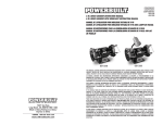
MODEL
#840116
8" BENCH DRILL PRESS
INSTRUCTION MANUAL
THIS MANUAL CONTAINS IMPORTANT INFORMATION REGARDING SAFETY, OPERATION,
MAINTENANCE AND STORAGE OF THIS PRODUCT. BEFORE USE, READ CAREFULLY AND
UNDERSTAND ALL CAUTIONS, WARNINGS, INSTRUCTIONS AND PRODUCT LABELS. FAILURE TO DO
SO COULD RESULT IN SERIOUS PERSONAL INJURY AND/OR PROPERTY DAMAGE.
FOR CUSTOMER SERVICE
POUR LE SERVICE APRÉS VENTE
OU DU CONSOMMATEUR
PARA EL SERVICIO
PARA EL CONSUMIDOR
87-1904-60957
KAWASAKI™ IS A TRADEMARK LICENSED BY KAWASAKI™
MOTORS CORP., U.S.A., WHICH DOES NOT MANUFACTURE OR
DISTRIBUTE THIS PRODUCT. CONSUMER INQUIRES SHOULD BE
DIRECTED TO:
1-800-590-3723
©COPYRIGHT 2005 ALLTRADE TOOLS, LLC.
1431 VIA PLATA
LONG BEACH, CA 90810-1462 USA
Printed in China
840116 – 8" Bench Drill Press_Rev 11/13/06
IF YOU SHOULD HAVE ANY QUESTIONS OR EXPERIENCE A PROBLEM WITH YOUR ALLTRADE
PRODUCT, DO NOT RETURN THIS PRODUCT TO THE STORE. PLEASE CALL OUR CUSTOMER SERVICE
DEPARTMENT AT 1-800-590-3723. BEFORE YOU CALL, HAVE THE FOLLOWING INFORMATION
AVAILABLE: MODEL No., DATE PURCHASED AND STORE LOCATION. AN ALLTRADE
REPRESENTATIVE CAN RESOLVE YOUR PROBLEM OVER THE PHONE. IF YOU WOULD LIKE TO MAKE
A SUGGESTION OR COMMENT, GIVE US A CALL OR EMAIL US AT: [email protected].
YOUR FEEDBACK IS VITAL TO US.
TABLE OF CONTENTS
CONGRATULATIONS! . . . . . . . . . . . . . . . . . . . . . . . . . . . . . . . . . . . . . . . . . 2
INTENDED USE . . . . . . . . . . . . . . . . . . . . . . . . . . . . . . . . . . . . . . . . . . . . . . 2
SECTION ONE
RECOGNIZE SAFETY SYMBOLS, WORDS AND LABELS . . . . . . . . . . . . 2-3
IMPORTANT SAFEGUARDS . . . . . . . . . . . . . . . . . . . . . . . . . . . . . . 3
SECTION TWO
GENERAL SAFETY RULES – FOR ALL ELECTRIC POWER TOOLS . . . . 4-5
GROUNDING INSTRUCTIONS . . . . . . . . . . . . . . . . . . . . . . . . . . . . 5-6
EXTENSION CORD USAGE . . . . . . . . . . . . . . . . . . . . . . . . . . . . . . . 6
IMPORTANT SAFETY RULES FOR DRILL PRESSES . . . . . . . . . . . . . . . 7-10
SYMBOLS . . . . . . . . . . . . . . . . . . . . . . . . . . . . . . . . . . . . . . . . . . . . . . . 10
SECTION THREE
FUNCTIONAL DESCRIPTION . . . . . . . . . . . . . . . . . . . . . . . . . . . . . . . . . 11
ASSEMBLY . . . . . . . . . . . . . . . . . . . . . . . . . . . . . . . . . . . . . . . . . . . . . . 12-16
INSTALLING THE COLUMN ASSEMBLY TO THE BASE . . . . . . . . . 13
SECTION FOUR
MAINTENANCE AND CLEANING . . . . . . . . . . . . . . . . . . . . . . . . . . . . . .
ACCESSORIES . . . . . . . . . . . . . . . . . . . . . . . . . . . . . . . . . . . . . . . . . . .
SPECIFICATIONS . . . . . . . . . . . . . . . . . . . . . . . . . . . . . . . . . . . . . . . . . .
OTHER CONSUMER DO-IT-YOURSELF (DIY) TOOLS . . . . . . . . . . . . . .
SECTION FIVE
2 YEAR LIMITED WARRANTY . . . . . . . . . . . . . . . . . . . . . . . . . . . . . . . .
25
25-26
26
27
27-30
CONGRATULATIONS!
Thanks for choosing this product. At Alltrade, our aim is to provide you with quality
products at an affordable price, and we want you to be totally satisfied with your
product and our Customer Service. If any help and advice is needed, please
contact us at 1-800-590-3723. Properly cared for, this product will give you many
years of satisfaction.
INTENDED USE
INSTALLING THE DRILL PRESS HEAD . . . . . . . . . . . . . . . . . . . . . 13
This product is intended for consumer use only. This tool is not designed for professional use. The power cord should only be used in approved electrical outlets as
described in this manual. Failure to use the proper power cords and/or extension
cords may result in fire or possible damage to the drill press.
INSTALLING HANDLES . . . . . . . . . . . . . . . . . . . . . . . . . . . . . . . . . . 14
RECOGNIZE SAFETY SYMBOLS, WORDS AND LABELS
INSTALLING THE WORK TABLE . . . . . . . . . . . . . . . . . . . . . . . . . . . 13
INSTALLING DRILL CHUCK . . . . . . . . . . . . . . . . . . . . . . . . . . . . . . 14-15
REMOVING AND INSTALLING DRILL BITS . . . . . . . . . . . . . . . . . . 15
MOUNTING THE DRILL PRESS . . . . . . . . . . . . . . . . . . . . . . . . . . . 16
LASER GUIDE . . . . . . . . . . . . . . . . . . . . . . . . . . . . . . . . . . . . . . . . . . . . 16-18
LASER SAFETY . . . . . . . . . . . . . . . . . . . . . . . . . . . . . . . . . . . . . . . . 16-17
OPERATING THE LASER . . . . . . . . . . . . . . . . . . . . . . . . . . . . . . . . . 17-18
OPERATING THE DRILL PRESS . . . . . . . . . . . . . . . . . . . . . . . . . . . . . . 19-25
OPERATING THE ON/OFF SWITCH . . . . . . . . . . . . . . . . . . . . . . . . . 19
ADJUSTING THE WORKTABLE . . . . . . . . . . . . . . . . . . . . . . . . . . . . 20
READ AND UNDERSTAND ALL INSTRUCTIONS. Failure to
follow all instructions in this manual may result severe in personal injury or
death. Keep this manual and refer to it for Safety Instructions, Operating
Procedures and Warranty.
The safety instructions provided in this manual are not intended to cover all possible conditions and practices that may occur when operating, maintaining and cleaning power tools.
Always use common sense and pay particular attention to all the DANGER,
WARNING, CAUTION and NOTE statements of this manual.
TILTING THE WORKTABLE . . . . . . . . . . . . . . . . . . . . . . . . . . . . . . . 21
ADJUSTING THE DRILL PRESS SPINDLE SPEED . . . . . . . . . . . . . 21-22
DRILLING HOLES TO SPECIFIED DEPTHS . . . . . . . . . . . . . . . . . . . 22-23
ADJUSTING THE SPINDLE RETURN SPRING . . . . . . . . . . . . . . . . 23-24
CORRECT DRILLING SPEEDS . . . . . . . . . . . . . . . . . . . . . . . . . . . . 24
WORKING WITH WOOD . . . . . . . . . . . . . . . . . . . . . . . . . . . . . . . . . 24
DRILLING METAL . . . . . . . . . . . . . . . . . . . . . . . . . . . . . . . . . . . . . . 25
1
This is the safety alert symbol. It is used to alert
you to potential personal injury hazards. Obey all
safety messages that follow this symbol to avoid
possible injury or death.
DANGER indicates an imminently hazardous
situation which, if not avoided, will result in death
or serious injury.
2
WARNING indicates a potentially hazardous
situation which, if not avoided, could result in
death or serious injury.
GENERAL SAFETY RULES – FOR ALL ELECTRIC POWER TOOLS
CAUTION indicates a potentially hazardous
situation which, if not avoided, may result in
minor or moderate injury.
READ AND UNDERSTAND ALL INSTRUCTIONS. Failure to follow all instructions
listed below may result in electric shock, fire and/or serious personal injury.
CAUTION used without the safety alert symbol
indicates a potentially hazardous situation which,
if not avoided, may result in property damage.
REMOVE ADJUSTING KEYS AND WRENCHES. Form a habit of checking to see
that keys and adjusting wrenches are removed from the tool before turning it on.
NOTE provides additional information that is useful
for proper use and maintenance of this tool. If a
NOTE is indicated make sure it is fully understood.
DO NOT USE TOOL IN A DANGEROUS ENVIRONMENT. Do not use power tools
in damp or wet locations, or expose them to rain. Keep work area well lit.
IMPORTANT SAFEGUARDS
People with electronic devices, such as pacemakers, should consult their
physician(s) before using this product. Operation of electrical equipment in
close proximity to a heart pacemaker could cause interference or failure of
the pacemaker.
WARNING: Some dust created by power sanding, sawing, grinding, drilling and
other construction activities contains chemicals known to the State of California
to cause cancer, birth defects or other reproductive harm.
Some examples of these chemicals are:
• Lead from lead-based paints.
• Crystalline silica from bricks and cement and other masonry products,
and arsenic and chromium from chemically-treated lumber.
Your risk from these exposures varies, depending on how often you do this type
of work. To reduce your exposure to these chemicals: work in a well ventilated
area, and work with approved safety equipment, such as dust masks that are
specially designed to filter out microscopic particles.
WARNING: Handling the power cord on corded products may expose you to
lead, a chemical known to the State of California to cause cancer and birth
defects or other reproductive harm. Wash hands after handling.
KEEP GUARDS IN PLACE AND IN WORKING ORDER.
KEEP WORK AREA CLEAN. Cluttered areas and benches invite accidents.
KEEP CHILDREN AWAY. All visitors should be kept a safe distance from the
work area.
MAKE YOUR WORKSHOP CHILD PROOF, with padlocks, master switches, or
by removing starter keys.
DO NOT FORCE TOOL. The correct tool will do the job better and safer at the
rate for which it is designed.
USE THE CORRECT TOOL FOR YOUR APPLICATION. Do not force tool or
attachment to do a job for which it was not designed.
ALWAYS USE SAFETY GLASSES. Also use a face mask or dusk mask if cutting
operation is dusty. Everyday eyeglasses only have impact lenses, they are NOT
safety glasses.
SECURE WORK. Use clamps or other practical ways to secure and support the
workpiece to a stable platform. Holding the work by hand or against your body
is unstable and may lead to loss of control.
DO NOT OVERREACH. Keep proper footing and balance at all times. Proper
footing and balance enables better control of the power tool in unexpected situations.
MAINTAIN TOOLS WITH CARE. Keep tools sharp and clean for best and safest
performance. Follow instructions for lubricating and changing accessories.
NEVER LEAVE TOOL RUNNING UNATTENDED. TURN POWER OFF. Don’t leave
tool until it comes to a complete stop.
DISCONNECT TOOLS before servicing and when changing accessories, such as
blades, bits, cutters and the like.
SAVE THESE INSTRUCTIONS FOR FUTURE REFERENCE.
3
4
REDUCE THE RISK OF UNINTENTIONAL STARTING. Be sure switch is in the
“OFF” position before plugging in.
USE RECOMMENDED ACCESSORIES. Consult the owners manual for recommended accessories. The use of improper accessories may cause cause risk of
injury.
NEVER STAND ON TOOL. Serious injury could occur if the tool is tipped or if
the cutting tool is unintentionally contacted.
CHECK DAMAGED PARTS. Before further use of the tool, a guard or other part
that is damaged should be carefully checked to determine that it will operate
properly and perform its intended function. Check for alignment of moving
parts, binding of moving parts, breakage of parts, mounting and any other conditions that may affect its operation. A guard or other part that is damaged
should be properly repaired or replaced.
DIRECTION OF FEED. Only feed work into a blade or cutter against the direction of rotation of the blade or cutter.
This drill press is equipped with a grounded 3-wire power cord with a 3-prong plug.
If the power cord will not fit into the wall plug, an approved adapter can be used as
long as it is connected to the center screw in the wall plate. See Figure 1 and the
steps below to use an AC grounding adapter:
1. Remove the cover plate mounting screw.
2. Insert the AC grounding adapter into the bottom receptacle so the green
grounding lug fits over the screw hole.
3. Install the mounting screw back into the cover plate securely affixing the
adapter to the receptacle.
Never modify the electrical adapter by cutting off the
grounding prong so it will fit into unapproved, un-grounded electrical receptacles. Failure to follow this procedure could result in burns, severe electrical shock, or even death.
If you have questions about connecting the drill press, contact a certified electrician
to install the proper circuitry needed for this and other power tools you use.
Repair or replace any damaged electrical wiring IMMEDIATELY.
GROUNDED RECEPTACLE
UNGROUNDED AC RECEPTACLE
GROUNDING INSTRUCTIONS
COVERPLATE
MOUNTING SCREW
NEVER use appliances or equipment that have motors
with automatic reset overload protective devices. These protective devices
can cause unexpected startups that can cause property damage, severe personal injury, or death.
The electrical power source for this drill press MUST be grounded in order to prevent
possible electric shock or even death should the tool malfunction or break down.
Grounding provides a path of least resistance for electric current thus reducing the
risk of electrical shock. The power source must also use a minimum 20A service.
Multiple power tools should never be used on the same circuit at the same time.
DRILL PRESS POWER CORD
GROUNDING ADAPTER
DRILL PRESS POWER CORD
FIGURE 1. CONNECTING THE DRILL PRESS TO THE AC POWER RECEPTACLE
Failure to properly ground this drill press could result in
burns, severe electrical shock, and even death. This is especially true if used in
damp or wet locations or near metallic plumbing. The reaction from electrical
shock could possibly cause your hands to make contact with the cutting tools.
Not all outlets are properly grounded, regardless of the
type of receptacle they have. If you are not sure if the receptacle is properly
grounded or not, consult a certified electrician. The AC receptacle must be
protected by a dual element time delay or a circuit breaker.
5
EXTENSION CORD USAGE
Extension cords are not recommended for use with this drill press. Extension cords, if
used, must be properly grounded with a 3-prong plug on one and a 3-hole receptacle on
the other. DO NOT use grounding adapters with an extension cord. Extension cords
must be UL listed and use a minimum of 18 A.W.G. wiring. Extension cords should never
exceed 25 feet in length. Extension cords, that are too long, cause a voltage drop over the
extra distance causing the grinder motor to run slower with the possibility of causing
damage to the motor. Using extension cords with smaller than the recommended wire
gauge run the risk of getting too hot, melting, and/or causing fires. See table, “Extension
Cord Specifications”, on page 25-26.
IMPORTANT SAFETY RULES FOR DRILL PRESSES
READ AND UNDERSTAND ALL INSTRUCTIONS. If there are instructions in this
manual that are not completely understood, seek the advice of a trained professional or contact Alltrade Customer Service at 1-800-590-3723 before attempting to perform the procedures. Failure to follow all instructions listed in this
manual may result in property damage, damage to the tool, or serious personal injury or even death.
DO NOT OPERATE THIS DRILL PRESS until it is completely assembled according to the instructions in this manual. Failure to adhere to these instructions
could result in serious and/or permanent injury to the operator.
FOLLOW ALL WIRING CODES. Use only properly grounded three-hole grounded receptacles. DO NOT cut the third prong off the power cord. When using an
extension cord, use only UL Listed extension cords with minimum 16 AWG
wiring and a maximum length of 25 feet. See ELECTRICAL SAFETY section in
this manual.
MAKE SURE APPROVED EYE PROTECTION IS BEING WORN and properly
adjusted and secured at all times the drill press is in use. Everyday eyeglasses
only have impact resistant lenses and ARE NOT safety glasses. Safety glasses
must conform to ANSI Z87.1 requirements. Approved safety glasses and
goggles will have Z87 printed or stamped on them.
KEEP BYSTANDERS, CHILDREN, AND VISITORS at a safe distance from the
drill press while it is in operation. Distractions can cause inadvertent misuse
resulting in possible injury to the bystanders or to the operator.
WEAR PROPER APPAREL. Do not wear loose clothing, gloves, neckties, rings,
bracelets, or other apparel that could possibly become caught in the moving
parts of the drill press. When working in a shop environment around power
tools, wear nonslip footwear. Use protective hair covering to contain long hair.
KEEP THE WORK AREA CLEAN AT ALL TIMES. Cluttered areas around the drill
press can cause unexpected accidents if the debris comes in contact with the
moving parts of the drill press.
MAINTAIN A PROPER WORK ENVIRONMENT. Do not operate the drill press in
damp or wet locations or expose it to rain. Water can cause the electrical
components to malfunction resulting in damage to the drill press and/or
serious injury or death to the operator.
ALWAYS USE APPROVED TABLE CLAMPS AND VICES to clamp work pieces to
the drill press table to prevent breakage, damage to the drill press, the work
piece, and possible severe injury to the operator. Contact Alltrade Customer
Service at 1-800-590-3723 (toll free) for authorized accessories.
USE ONLY DRILL BITS, SANDING DRUMS, AND OTHER ACCESSORIES that
are designed for the various speeds of this drill press. The drill bits, sanding
drums and other accessories should have a shank size 1/2" OR SMALLER.
Unsuitable drill bits can break without warning throwing fragments outward at
high speeds possibly causing severe injuries. Contact Alltrade Customer
Service at 1-800-590-3723 (toll free) for authorized drill bit specifications.
USE RECOMMENDED SPEED for drill accessory and workpiece material.
DO NOT FORCE THE TOOL. The drill press will do a better job and be safer if
drilling operations are performed at the proper speeds as expressed in this
manual.
USE ONLY THE CHUCK KEY THAT IS PROVIDED with the drill press or a
duplicate of it to reliably secure the drill bit inside the chuck.
REMOVE CHUCK KEYS AND OTHER ADJUSTMENT TOOLS from the areas
around the drill press before turning the power switch to the “ON” position.
DO NOT USE A DRILL BIT THAT WOBBLES OR VIBRATES. Visually inspect the
drill bits before they contact the work piece ensuring there are no side-to-side
movements. Should the drill bit wobble from side-to-side or if the tip appears
broken, replace them immediately. If the vibration still exists, check the bearings and the motor shaft and repair or replace them as soon as possible.
EXCESSIVE VIBRATION can cause severe damage to both the work piece and
the drill press.
ADJUST THE TOOL TABLE BEFORE EACH USE. The tool table should be tightened and placed at the proper angle for the drilling job before the drill press is
put into use. If not properly adjusted, the work piece can unexpectedly move
causing the drill bit to seize resulting in damage to it or possible severe injury
to the operator.
DO NOT STAND DIRECTLY IN FRONT OF THE DRILL PRESS when it is first
turned on. Loose fragments could fly off at high speeds possibly causing injury.
PROPERLY SUPPORT EXTRA LONG OR EXTRA WIDE WORK PIECES. Work
pieces that are too long or tool wide can tip and cause the drill bit to seize
resulting in a sudden whipping motion resulting in damage to the work piece
and drill press as well as possible severe injury to the operator.
NEVER START THE DRILL PRESS WITH THE WORK PIECE IN CONTACT WITH
THE DRILL BIT. The sudden start-up of the drill bit could cause it to seize resulting in a sudden, rapid spinning motion that could damage the work piece, the
drill press, and/or serious injury to the operator.
8
DISCONNECT THE DRILL PRESS POWER CORD FROM THE AC OUTLET before
making adjustments to the worktable, clamps, vises, work pieces, changing drill
bits, or changing the speed of the drill motor preventing the tool from accidentally turning on. Failure to adhere to this step could result in
damage to both the work piece and the drill press as well as possible severe
injury to the operator.
THOROUGHLY CLEAN THE DRILL PRESS before changing types of work
pieces. Combining wood and metal dust can result in an explosion or fire. CONSULT EXPERT advice before drilling in work pieces made of magnesium. The
friction generated by the drill bit could the magnesium to ignite resulting in a
very intense fire that could cause severe burns to the operator and/or
seriously damage the drill press.
NEVER PERFORM DRILLING OPERATIONS NEAR FLAMMABLE GAS OR
LIQUIDS. The resulting fire and/or explosion could cause permanent serious
injuries to the operator and damage to the drill press and surrounding work area.
ALWAYS KEEP ARMS, HANDS, AND FINGERS away from the work piece while
it is on the table and the drill press is turned on. Severe injury could result.
ALWAYS CLAMP THE WORK PIECE FIRMLY AGAINST THE WORK TABLE.
Never attempt to hold the workpiece by hand. The drill bit can seize in the work
piece causing it to spin rapidly. This will cause loss of control of the work piece
resulting in severe injuries or damage to the work piece and drill press.
NEVER APPLY A COOLANT directly to the work piece while it is in contact with
the drill bit. Coolant can weaken the makeup of the drill bits causing them to fail.
NEVER PERFORM LAYOUT OR ASSEMBLY to work pieces in front of the drill
press while it is still running. A sudden slip could bring hands in contact with
the moving parts of the drill press resulting in injury to the operator.
SECURE THE ELECTRICAL POWER CORD when the drill press is not in use to
prevent unauthorized use of the tool and/or to prevent children from accidentally turning it on.
ADDITIONAL INFORMATION about the proper use of bench-mounted drill
presses is available from the Power Tool Institute, 1300 Sumner Avenue,
Cleveland, OH 44115-2851 (www.powertoolinstitute.com). Information is also
available from the National Safety Council, 1121 Spring Lake Drive, Itasca, IL
60143-3201. Additionally, you can refer to the American National Standards
Institute (ANSI) 01.1 Safety Requirements for Woodworking Machines and the
U.S. Department of Labor OSHA 1910.213 Regulations.
USE COMMON SENSE WHEN OPERATING THIS DRILL PRESS OR OTHER
POWER TOOLS. Never try to perform drilling operations on work pieces that are
too large to be clamped to the worktable or vises. Keep this manual and refer to it
often to ensure proper operation and prevent unnecessary accidents or injuries.
SYMBOLS
IMPORTANT: Some of the following symbols may be used on your tool. Please
study them and learn their meaning. Proper interpretation of these symbols will
allow you to operate the tool better and safer.
SYMBOL
V
A
Hz
W
Kg
REDUCE THE RISK OF UNINTENTIONAL STARTING. Ensure the “ON/OFF” switch
is set to the “OFF” position before plugging the power cord into the AC outlet.
TURN THE ON/OFF SWITCH on the drill press to the “OFF” position and unplug
the power cord from the electrical receptacle when the drilling operations are
finished. Thoroughly clean the area surrounding the drill press making it ready
for the next use.
NEVER LEAVE THE DRILL PRESS RUNNING UNATTENDED. when finished with
a drilling operation, turn “off” the drill press and wait until it comes to a
complete stop.
9
min
s
!
NAME
Volts
Amperes
Hertz
Watt
Kilograms
Alternating Current
Direct Current
Alternating or Direct Current
Earthing Terminal
Class II Construction
Minutes
Seconds
Diameter
.../min
No load speed
Revolutions per Minute
1,2,3, …
Ring Selector Settings
EXPLANATION
Voltage (Potential)
Current
Frequency (Cycles per Second)
Power
Weight
Type of Current
Type of Current
Type of Current
Grounding Terminal
Denotes Double Insulation
Time
Time
Size of Drill Bits,
Grinding Wheels, etc.
No-load Rotational Speed
Revolutions, Surface Speed,
Strokes, etc. per Minute
Speed, Torque or Position Settings
FUNCTIONAL DESCRIPTION
ASSEMBLY
5
3
Do not begin assembly of Bench-mounted Drill Press if the AC power cord is
plugged into an AC power receptacle.
6
Do not begin assembly of Bench-mounted Drill Press if power switch on the
front of the base is switched to the “ON” position.
2
INSPECTION: Carefully inspect each individual part of the drill press to ensure there
are no cracked, broken, or bent components.
8
4
12
1
5
7
9
10
1. Carefully choose a location for the bench-mounted drill press. If mounted on a
workbench, ensure there is adequate room all around the drill press for safe
operation. The area must be level and clear of other power tools and/or power
tool cords that could interfere with operation of the drill press.
2. If the drill press is installed on a universal tool stand (available at larger hardware stores), ensure there is plenty of unobstructed space around the drill
press as not to interfere with safe operation on the tool.
3. Use clamps or a vise to hold workpiece securely in place.
13
11
CONTROLS AND COMPONENTS:
1. Drill Bit
2. Column Assembly
3. Feed Handles
4. Chuck Key
5. Drill Chuck
5. Head Assembly
6. Knob (and mtg Hardware)
7. Work Table
8. Table Support Lock
Assembly
9. Work Table Clamp
10. Column Base
11. Grounded Power Cord
12. Hex Wrenches
13. Column Assembly mtg Hardware
11
4. The drill press should be installed in a place that is away from outside elements
and close to an approved power receptacle so that an extension cord will not be
needed. Should an extension cord be needed, refer to Page 25 in this manual
for choosing the proper length and wire gauge needed for safe operation of the
drill press.
5. Do not assemble and/or use the drill press in an area that may be contaminated
with oily rags. Keep flammable materials such as gasoline, paint thinner or solvents. Sparks from normal drilling operations can ignite these compounds
resulting in moderate to severe burns to the operator.
12
INSTALLING THE COLUMN ASSEMBLY
TO THE BASE
1. Place the base (1) on a firm level surface.
2. Secure the column assembly (2) to the base (A)
using the three hex-head screws (3) provided.
See Figure 2.
Ensure the spindle taper (Q) and the tapered hole in the
drill chuck (R) are clean and free of any grease, lacquer, or rust preventative
coatings. These compounds can cause the drill chuck (R ) to seize when
installed on the spindle shaft (Q).
2
3
3
FIGURE 2.
ATTACHING THE COLUMN
ASSEMBLY
1
1
INSTALLING HANDLES
1. Insert the three drill press feed handles (2) into the tapped holes on the
pinion shaft (1). See Figure 5.
4
3
2
2. Using a Phillips screwdriver, insert
screw (4) into knob (3) and install it
on the drill press cover.
2
INSTALLING THE WORK TABLE
1. Slide the worktable (1) and table clamp
bracket (2) onto the column assembly (3).
1
2
2. Install the support lock handle (4) into the
clamp bracket (2).
FIGURE 3.
INSTALLING THE WORK TABLE
FIGURE 5.
INSTALLING HANDLES
3. Position the worktable to the desired height
and tighten the support lock handle (4).
1
INSTALLING THE DRILL PRESS
HEAD
1. Place the drill press head (1) onto
the column assembly (2). Press
the drill press head (1) downward
on the column assembly (2) as far
as it will go.
5
4
2. Align the drill press head (1) with
the worktable (3) and the base.
2
3. Tighten the two head locking
screws (4) as shown in Figure 4,
with the hex-wrench (5) supplied.
3
FIGURE 4.
INSTALLING THE DRILL PRESS
AND MOTOR
13
INSTALLING THE DRILL CHUCK
1. Open the jaws of the drill
chuck (1) as wide as possible
by turning the chuck sleeve (2).
2. Holding the drill chuck (1) on
the tapered end of the spindle
shaft, use a soft tip (rubber)
hammer (3) or a block of wood
and a hammer.
2
1
3. Tap the drill chuck (1) onto the
spindle shaft. See Figure 6.
FIGURE 6.
INSTALLING THE DRILL CHUCK
14
3
MOUNTING THE DRILL PRESS
During operation of the drill press,
there may be instances where the tool
could tip over, slide, or walk on the
supporting surface. To secure the drill
press:
To avoid damage to the drill chuck and the spindle shaft,
do not drive the chuck onto the spindle shaft with a metal hammer. Damage
to the Drill Chuck will occur.
REMOVING AND INSTALLING DRILL BITS
1. Place the drill press (1) on the
workbench (2) as desired.
Disconnect drill press from AC power source and ensure
the “ON/OFF” switch is in the “OFF” position. Failure to adhere to this warning could cause severe, permanent injury to the operator.
3
Use only the chuck key provided by the manufacturer
with the drill press.
1
1. Use the chuck key (1) to
loosen the drill chuck (2).
See Figure 7.
2. Insert the smooth end of
the drill bit (3) into the drill
chuck (2) as far as it will
go.
2. Secure the drill press (1) to the
workbench (2) using two carriage
bolts (3), flat washers (4), and
nuts (5) through the holes in the
drill press base. See Figure 8.
3
2
4
2
3. Back the drill bit (3) out
approximately 1/16" or up
to the flutes for smaller
bits.
4
3
1
4. Ensure the drill bit (3) is
centered in the drill chuck
jaws before tightening.
FIGURE 7.
INSTALLING DRILL BITS
5. Use the chuck key (1) and
tighten the drill chuck (2)
locking the drill bit (3) in place.
FIGURE 8.
MOUNTING THE DRILL PRESS
5
LASER GUIDE
Use of controls or procedures, or performance of procedures other then those specified herein may result in hazardous radiation
exposure.
LASER SAFETY
IMPORTANT: Lock all three jaws in the drill chuck bit to ensure proper tightening and
so it doesn’t slip while drilling.
6. Ensure the check key (1) is removed from the drill chuck BEFORE applying
power to the drill press.
7. The chuck key is equipped with a self-ejecting pin (4) that helps minimize the
hazard of the key being inadvertently left in the drill chuck.
15
NEVER LOOK INTO THE LASER BEAM. Any contact with the eyes by the beam
could cause injury. Do not use the laser when cutting reflective materials.
DO NOT AIM THE LASER BEAM AT ANYONE OR AT REFLECTIVE SURFACES.
CLASS 2M LASER PRODUCT. Any contact with the eyes by the beam could
cause injury. Ensure the laser beam is turned on only when the tool is on a nonreflective workpiece and as such it is aimed only at the work surface. Metals and
other materials like steel which can be highly reflective should only be cut without the use of the laser.
TO CHANGE LASER BATTERIES:
1. Turn off the laser.
STORE OUT OF REACH OF CHILDREN. Equipment should be in a high location
or locked up to keep out of reach of children. It is not a toy.
DO NOT TAMPER WITH THE LASER OUTPUT. Changing the performance of the
laser to increase its output is prohibited. Any claim for damages or injuries
resulting from not following these instructions will be refused.
OPERATION ACCESSIBLE FIELDS:
Wavelength
Laser Power for Classification
636-660nm
<1mW CW
2. Press the tab (1) located below the laser
switch (2) and lift up the laser switch
cover.
AVOID EXP
OSUR
E
CAUTI
O
N
LASER
RADI
ATIO
N
3. Insert two “AAA” batteries in the laser
battery compartment (3).
1
(ON/OFF SWITCH)
4. Close the laser switch cover.
CAUTION LABEL
(LASER APERTURES)
NEVER OPERATE LASER IF THE UNIT IS DEFECTIVE OR THE COVER OR SEAL
IS DAMAGED.
DO NOT SERVICE LASER. The laser unit must be returned to the factory for any
service or repair. Service or repair must be handled by authorized factory
trained technicians.
AVOID EXP
OSUR
E
CAUTI
O
N
LASER
RADI
ATIO
N
Do not open the laser unit except to change batteries.
REMOVE BATTERIES IF THE LEVEL IS TO BE STORED FOR ANY LENGTH OF
TIME. Batteries may leak and damage the laser if it is stored idle for more than
3 months.
Be careful with this tool. Striking or jarring it, especially on the laser housing,
can affect its accuracy.
2
3
CAUTION LABEL
FIGURE 9.
INSTALLING LASER BATTERIES
Other than batteries, there are no user-serviceable parts in the laser device.
USING THE LASER LIGHT:
1. Place the workpiece on the table.
LASER LIGHT
DO NOT VIEW DIRECTLY WITH OPTICAL
INSTRUMENTS (MAGNIFIERS)
CLASS 2M LASER PRODUCT
635-660nm, <1mW CW
CLASSIFIEDS PER IEC 60825-1, Ed. 1.2, 2001-08
2. Turn the laser switch to the ON position.
LASER RADIATION
CAUTION LABEL
AVOID EXPOSURE LASER LIGHT IS
EMITTED FROM THIS APERTURE.”
3. Lower the drill bit to meet the workpiece. The two laser lines should cross
where the drill meets the workpiece.
AVOID EXP
OSUR
E
CAUTI
O
N
LASER
RADI
ATIO
N
4. If the drill needs to be adjusted:
• Using a 3mm hex key, turn the laser
adjustment set keys counter-clockwise.
OPERATING THE LASER
Do not stare directly into the Laser beam, aperture or
into a reflection from a mirror-like surface.
The laser runs on two AAA batteries which are located beneath the “ON/OFF” switch.
When the laser light begins to dim, change both batteries. NEVER mix old batteries
with new.
17
• Rotate the laser light housing until
the two laser lines intersect where
the drill meets the workpiece. DO
NOT stare directly at the laser lines.
5. Re-tighten the adjustment set screws.
FIGURE 10. USING THE LASER LIGHT
18
OPERATING THE DRILL PRESS
The drill press is designed to use drill bits with a shank of 1/2" or less. The following will give the inexperienced operator practice with common drilling operations.
Always use scrap material and do test procedures before working on the actual
workpiece. These test runs will decrease as experience and confidence with the drill
press increase.
When the workpiece is long enough, place it on the
worktable so that one end rests against the drill press column. This is
usually the left side as you look to the rear of the drill press. In case the drill
bit seizes in the workpiece, the drill press support will prevent the workpiece
from spinning out of control. FAILURE to adhere to this step could result in
possible severe injury to the operator.
OPERATING THE ON/OFF SWITCH
The drill press “ON/OFF” switch is located on the front of the drill press head. To
turn the drill press “ON,” move the rocker-style switch up to the “ON” position. To
turn the drill press “OFF,” move the rocker-style switch down to the “OFF” position.
Ensure the “ON/OFF” switch is in the “OFF” position
before plugging the power cord into the AC power source. Ensure there are
no tools or work pieces in contact with the drill bits, cutting tools, or sanding drum when the drill press is turned “ON.” Failure to observe these procedures could result in damage to the drill press, tools, work pieces, and/or
serious personal injury to the operator or bystanders.
Ensure that the switch toggle, when removed, is kept in
a secure place. Once removed, the drill press will not start without it.
ADJUSTING THE WORK TABLE
1. The worktable (1) can be raised or lowered on the drill press column (2) by
loosening the table clamp (3). See
Figure 12.
2. After the table is positioned at the
desire height, LOCK the table in place
by tightening the table clamp (3). NOTE:
Final positioning of the table should
always be made from the bottom to the
up position.
3. The worktable (1) can be rotated 360
degrees around the column (2) by loosening the table clamp (3). Rotate the
table to the desired position and LOCK
the table in place by tightening the table
clamp (3). See Figure 12.
Anytime the drill press is not being
used, the “ON/OFF” should be
locked to prevent any unauthorized use.
1. To LOCK the “ON/OFF” switch,
grasp the switch toggle (1) and
remove it from the “ON/OFF”
switch (2). See Figure 11.
2
FIGURE 11.
LOCKING THE “ON/OFF” SWITCH
19
1
3
FIGURE 12. ADJUSTING THE WORK TABLE
LOCKING THE “ON/OFF” SWITCH IN THE “OFF” POSITION
1
2
20
1. Lift up the pulley cover (1).
TILTING THE WORKTABLE
1. The worktable (1) can be tilted to the left
or right by loosening the pivot bolt (4)
mounted beneath the worktable. See
Figure 13.
2. Tilt the worktable (1) to the desired position and tighten the pivot bolt (4).
2
1
3
4
FIGURE 13.
TILTING THE WORK TABLE
3. When returning the table to the level
position, line up the register mark on the
table with the tilt scale. This ensures the
table surface is positioned 90 degrees to
the spindle.
4. A tilt scale (K) is provided on the table
bracket casting (L) to indicate the degree
of tilt.
5. A witness line and zero mark (1) are provided on the table to ensure proper
alignment with the tilt scale (2).
ADJUSTING THE DRILL PRESS SPINDLE SPEED
A spindle speed and pulley/belt arrangement chart is posted inside the pulley cover.
See the chart below. Refer to this chart whenever spindle speeds need to be
changed.
620
1100
2340
1720
3100
6
4
2. Release the belt tension by loosening the tension lock knob (2) located
on the side of the drill press head.
Loosen the tension lock knob (2) by
turning it counterclockwise.
3. Pivot the motor (3) towards the
front of the drill press.
5
1
4. While holding the motor pivoted to
the front of the drill press, position
the belt (4) on the desired step of
the motor pulley (5) and the spindle
pulley (6). See Figure 14.
3
2
5. After attaining the desired spindle
speed, pivot the motor (3) to the
rear of the drill press and securely
tighten the tension lock knob (2) by
turning it clockwise.
6. The belt (4) should be tight enough
to prevent any slippage. If the belt is
overtightened, the life of the belt will
be noticeably reduced.
7. Close the pulley cover (1).
FIGURE 14.
ADJUSTING DRILL PRESS SPEED
DRILLING HOLES TO SPECIFIED DEPTHS
Disconnect drill press from AC power source and ensure
the “ON/OFF” switch is in the “OFF” position. Failure to adhere to this warning could cause severe, permanent injury to the operator.
A depth stop (1) is provided on the pinion shaft, allowing multiple holes to be
drilled to a specific depth. See Figure 15.
Disconnect drill press from AC power source and ensure
the “on/off” switch is in the “OFF” position. Failure to adhere to this warning could cause severe, permanent injury to the operator.
21
22
1. Insert drill bit (2) into drill chuck.
1
2. Lower the spindle (3) until the pointer
(4) is in line with the mark on the
scale (5).
4
5
3. Tighten the lock screw (6).
4. Return the spindle (3) to the up position.
5. Place the workpiece on the drill press
table and securely clamp it in place.
6
3
6. Raise the drill press table until the
workpiece just touches the end of the
drill bit (2).
2
3. Turn the spring housing (5) counterclockwise to increase the spring tension or clockwise to decrease the
spring tension.
4. Turn nut (4 - inside) until it contacts
the spring housing (5). Back nut (4)
out 1/4 turn and tighten it against
nut (3 - outside) to hold the spring
housing in place.
3
4
2
1
5. IMPORTANT: The inside nut (4)
should not touch the spring housing
(5) after it has been tightened.
5
FIGURE 16.
ADJUSTING SPINDLE
RETURN SPRING
7. Drill a test hole and check the depth.
Make any adjustments as necessary.
FIGURE 15.
DRILLING HOLES TO SPECIFIED DEPTHS
CORRECT DRILLING SPEEDS
ADJUSTING THE SPINDLE RETURN SPRING
Disconnect drill press from AC power source and ensure
the “ON/OFF” switch is in the “OFF” position. Failure to adhere to this warning could cause severe, permanent injury to the operator.
The spindle return spring (1) is automatically returned to its upper position when
the pinion shaft handles (2) are released. It is recommended that the pinion shaft
handles (B) be allowed to return to the upper position slowly. DO NOT LET GO OF
THE HANDLES after the hole has been drilled. This action will cause excessive wear
and tear on spindle return spring. To adjust the spindle return spring, See Figure 15
and follow the steps below:
1. Loosen the two nuts (3 and 4). Ensure the housing stays engaged with the
head casting.
2. While firmly holding the spring housing (5), pull out the housing until the boss
is engaged with the next notch on the housing.
The correct drilling speed is determined by type of material being drilled, the size of
the hole, the type of the drill bit or cutter, and the desired quality of the hole.
Always use the recommended speed for the drill bit and
for the type of materials the workpiece is made of. If you have any questions
as to the proper speeds or types of materials, contact Alltrade customer
service at 1-800-590-3723.
WORKING WITH WOOD
Twist drills, although designed for drilling metal, can also be use for drilling wood.
However, it is recommended that machine spur bits or wood-boring bits be used for
wood projects. These bits cut a flat bottom hole and are designed to remove to easily remove wood chips. DO NOT USE hand bits designed for a hand-operated drill
brace. These bits have screw tips and at the speeds used by the drill press, they
would rapidly engage the workpiece and spin it around violently.
For through boring, line up the spot where the hole is to drilled with the hole in the
worktable. This permits the drill bit to pass cleanly through the workpiece without
damaging the worktable. Scribe a vertical line on the front of the column and matching marks on the table bracket and the drill press head so that the table and drill
press can be clamped in the center position at any height.
23
To prevent splintering on the bottom of the workpiece, clamp a scrap piece of wood
beneath the workpiece and allow the drill bit to enter it resulting in a clean hole on
the workpiece. This also protects the point of the drill bit.
DRILLING METAL
Always use clamps or a vise when drilling metal. The
workpiece should never be held in place by hand.
The drill bit could seize in the metal at any time, especially when breaking through
the backside of the workpiece. This could cause the workpiece to spin out of the
operator’s hand. The drill bit will be broken when the workpiece strikes the column.
Failure to observe this precaution could result in damage to the workpiece, the drill
press, and severe or permanent injury to the operator.
CONSULT EXPERT ADVICE BEFORE DRILLING IN WORK PIECES MADE OF MAGNESIUM. The friction generated by the drill bit could cause the magnesium to ignite
resulting in a very intense fire that could cause severe burns to the operator and/or
seriously damage the drill press.
The workpiece must be clamped firmly while drilling. Tilting, twisting, or shifting not
only results in a rough-drilled hole, but increases the risk of breaking the drill bit.
For flat work, place the workpiece on a piece of scrap wood and clamp tightly to the
worktable to prevent it from turning. If the shape of the workpiece is irregular and
cannot be placed flat on the table, it should be securely blocked and clamped before
attempting to use the drill press.
MAINTENANCE AND CLEANING
LASER MAINTENANCE
For the best laser performance, perform the following maintenance regularly:
1. Disconnect machine from power source.
2. Carefully clean sawdust from each laser lens. Do not use solvents of any kind
since they may damage the lens. Dust build-up can block the laser and prevent
it from accurately indicating the line of drilling.
ACCESSORIES
Optional accessories for the drill press can include wire-brush wheels that can be
used for cleaning and layered cloth wheels that can be used for polishing and buffing. Contact ALLTRADE Customer Service at 1-800-590-3723 (toll free) to find out
what accessories are available for the drill press.
Only use accessories that are designed to fit your particular drill press. These accessories should be specifically labeled to match
the speed and arbor size of the drill. Failure to use the proper accessories
could result in property damage, damage to the grinder, and serious personal injury to the operator.
Always attach grounded (3-prong) extension cords to grounded (3-hole) outlets.
If the drill press must be used outside, use an extension cord labeled “W-A” or “W.”
These extension cords are rated for outdoor use and reduce the chances of electrical shock.
If you must use an extension cord, be sure that the gauge is large enough to carry
the amount of current necessary for your power tool. If not, your tool may experience a loss of power, excessive voltage drop or overheating. The smaller the gauge
number, the heavier the cord (see table below).
RECOMMENDED SIZES OF EXTENSION CORDS 120 VOLT AC 60 HZ TOOLS
TOOL CURRENT RATING
CONDUCTOR SIZE IN A.W.G
AMPERE
10FT.
25FT.
50FT.
100FT.
3-6
18
18
18
18
6-8
18
18
18
16
8-10
18
18
18
14
10-12
16
16
14
14
12-16
14
12
12
16-20
12
12
12
SPECIFICATIONS
SPECIFICATIONS
Voltage
Rated Current
No-Load Speed (motor)
Max. Distance
From Spindle Axis
To Surface Of Column:
Max. Distance
From Spindle End
To Surface Of Table:
Distance:
Spindle axis to column
Spindle Travel:
Chuck Capacity
Range of Spindle Speeds
(60Hz)
Laser Beam
Laser Beam Maximum
Power
Laser Beam Wavelength
120V
60 Hz
1.8 A
1700 RPM
4 1/8" (105mm)
7" (178mm)
4.0" (102mm)
2" (51mm)
1/2" (13mm)
620-3100 RPM
Class II, Diode Laser
1mw
650nm
26
OTHER CONSUMER DO-IT-YOURSELF (DIY) TOOLS
Alltrade offers a full range of Kawasaki™ tools that make DIY jobs easy. If you would
like further information on the following products, please contact Alltrade Customer
Service Department at 1-800-590-3723.
Cordless Drills/Screwdrivers
Impact Wrenches
Sanders
Jigsaws
Circular Saws
Angle Grinders
Reciprocating Saws
Routers
Rotary Tools
Corded and Cordless Multi-Purpose Tools
Wide Range of Accessories and more
2 YEAR LIMITED HOME USE WARRANTY
Express and Exclusive Limited Home Use Warranty to Original Retail Buyer
Alltrade Tools LLC (hereinafter "Alltrade") expressly warrants to the original retail
purchaser of the accompanying KAWASAKI™ portable power tool and no one else
all parts of the product (except those parts referred to below which are specifically
excluded from such warranty (see Exclusions)) to be free from defects in materials
and workmanship for a period of two years from original date of purchase.
SPECIAL WARRANTY NOTE TO CONTRACTORS AND COMMERCIAL USERS: This
Kawasaki™ portable power tool is offered as a home use tool and carries a HOME
USE WARRANTY. This tool is made for home use in the execution of
projects and repairs in and around the home. Use of the tool for COMMERCIAL
PURPOSES OR ON A JOBSITE is not covered under this warranty.
The date of purchase shall be the date of shipment to the original purchaser, or the
date the original purchaser took possession, custody or control of the product,
whichever occurred first. This warranty shall be null and void if the product or any
component thereof is modified, altered or used for any commercial purpose or on
a jobsite. This warranty does not apply to any other product and/or component
thereof manufactured or distributed by Alltrade, and does not apply to products
and/or components thereof designed, manufactured and/or assembled by others,
for which Alltrade makes no warranties whatsoever. THERE ARE NO WARRANTIES
WHICH EXTEND BEYOND THE DESCRIPTION ON THE FACE HEREOF.
27
Warranty Performance
By purchasing the product, purchaser expressly acknowledges and agrees that their
sole and exclusive remedy under this warranty shall be strictly limited to the repair
or replacement of any covered nonconforming items or parts thereof provided that
any such nonconforming item and/or part is promptly returned to Alltrade’s facility
postage pre-paid and insured (address: ALLTRADE Warranty Claims & Repair,
1431 Via Plata, Long Beach, CA 90810, Attn: Customer Service #1-800-590-3723)
within the applicable warranty period, with a written request by purchaser that
Alltrade repair and/or replace the nonconforming item and/or part. We recommend
that you keep the original product packaging in the event you need to ship the unit.
We suggest the package be insured against loss or in transit damage. When
sending your product include your name, address, phone number, dated proof
of purchase (or copy), and a statement about the nature of problem. Warranty
coverage is conditioned upon purchaser furnishing Alltrade with adequate written
proof that they are the original purchaser and of the original purchase date. Parts
returned, freight prepaid and insured, to Alltrade’s facility (see above address) will
be inspected and, at Alltrade’s option, repaired and/or replaced free of charge if
found to be defective and subject to warranty. Alltrade retains the sole discretion
to determine whether any item or part is nonconforming and, if so, whether the
item and/or part will be repaired and/or replaced. If the unit is repaired, new or
reconditioned replacement parts may be used. If Alltrade chooses to replace
the product, it may replace it with a new or reconditioned one of the same or
comparable design. The repaired or replaced unit will be warranted under the terms
of the remainder of the warranty period. Typically, a defective product that is
returned within the first 30 days after the purchase date will be replaced; for items
returned after the first 30 days and within the warranty period, covered defective
parts not subject to normal wear and tear or other exclusions will be repaired or
replaced, at Alltrade’s option. During the warranty period, Alltrade will be responsible for the return shipping charges. Alltrade’s repair and/or replacement of any nonconforming item and/or part thereof shall constitute fulfillment of all
obligations to the purchaser. Alltrade shall not be responsible or liable for any
expense, including freight charges, or repairs made outside Alltrade’s facility, unless
expressly agreed to by Alltrade in writing. Under no circumstances shall Alltrade
bear any responsibility for loss of the unit, loss of time or rental, inconvenience,
commercial loss or consequential damages.
Exclusions
This warranty does not cover parts damaged due to normal wear, abnormal
conditions, misapplication, misuse, abuse, accidents, operation at other than
recommended pressures or temperatures, improper storage or freight damage.
Parts damaged or worn by operation in dusty environments are not warranted.
Failure to follow recommended operating and maintenance procedures also
voids warranty.
28
This limited warranty does not apply to accessory items such as drill bits,
screwdriving bits, circular saw blades, jigsaw blades, grinding wheels, sanding
sheets and other related items.
DAMAGE TO THE PRODUCT RESULTING FROM TAMPERING, ACCIDENT, ABUSE,
NEGLIGENCE, FAILURE TO FOLLOW INSTRUCTIONS, UNAUTHORIZED REPAIRS
OR ALTERATIONS, DAMAGE WHILE IN TRANSIT TO OUR SERVICE FACILITY,
USE OF UNAPPROVED OR IMPROPER ATTACHMENTS OR ACCESSORIES,
COMMERCIAL AND RENTAL APPLICATIONS OR OTHER CAUSES UNRELATED TO
PROBLEMS WITH MATERIAL OR WORKMANSHIP ARE NOT COVERED BY THIS
WARRANTY.
Alltrade will not be liable for the following: labor charges, loss or damage resulting
from improper operation, maintenance or repairs made by other persons;
pre-delivery services such as assembly, oil or lubricants, and adjustment;
maintenance services that are normally required to maintain the product.
The use of other than genuine Alltrade Repair Parts will void warranty.
Warranty Disclaimers
EXCLUSION AND DISCLAIMER OF ALL OTHER EXPRESS WARRANTIES,
GUARANTIES AND/OR REPRESENTATIONS. EXCEPT FOR THE LIMITED WARRANTY
PROVIDED ABOVE, ALL OTHER EXPRESS WARRANTIES, GUARANTIES AND/OR
REPRESENTATIONS BY ALLTRADE AND/OR ITS REPRESENTATIVE(S) REGARDING
THE DESIGN, MANUFACTURE, PURCHASE, USE AND/OR OPERATION OF THE
PRODUCT OR ANY COMPONENT THEREOF SOLD HEREUNDER, REGARDLESS OF
WHETHER ANY SUCH WARRANTY, GUARANTY AND/OR REPRESENTATION,
WRITTEN OR ORAL, ARISES BY OPERATION OF LAW AND/OR EQUITY AND/OR BY
ANY ACT OR OMISSION OF ALLTRADE AND/OR ITS REPRESENTATIVE(S), OR THE
BUYER, ARE HEREBY EXPRESSLY EXCLUDED AND DISCLAIMED BY ALLTRADE
AND/OR ITS REPRESENTATIVES. PURCHASER KNOWINGLY AND WILLINGLY
WAIVES ANY AND ALL SUCH WARRANTIES AND RIGHTS, CLAIMS AND/OR
CAUSES OF ACTION ARISING THEREFROM OR BASED THEREON. PURCHASER’S
SOLE AND EXCLUSIVE REMEDY IS AS STATED ABOVE.
ALLTRADE AND/OR ITS REPRESENTATIVE(S), OR THE PURCHASER, INCLUDING
BUT NOT LIMITED TO THE IMPLIED WARRANTY OF MERCHANTABILITY AND THE
WARRANTY OF FITNESS FOR A PARTICULAR PURPOSE, ARE HEREBY EXPRESSLY
EXCLUDED AND DISCLAIMED BY ALLTRADE AND/OR ITS REPRESENTATIVES.
PURCHASER KNOWINGLY AND WILLINGLY WAIVES ANY AND ALL SUCH
WARRANTIES AND RIGHTS, CLAIMS AND/OR CAUSES OF ACTION ARISING
THEREFROM OR BASED THEREON. PURCHASER’S SOLE AND EXCLUSIVE
REMEDY IS AS STATED ABOVE.
Limitation Of Liability
IN NO EVENT SHALL ALLTRADE AND/OR ITS REPRESENTATIVE(S) BE LIABLE FOR
INDIRECT, INCIDENTAL, SPECIAL AND/OR CONSEQUENTIAL DAMAGES OF ANY
KIND ARISING OUT OF OR RELATED TO, DIRECTLY OR INDIRECTLY, ANY BREACH
OF ANY PROVISION OF ANY AGREEMENT BETWEEN ALLTRADE AND/OR ITS
REPRESENTATIVE(S) AND PURCHASER, ANY WARRANTY HEREUNDER,
AND/OR THE EXISTENCE, DESIGN, MANUFACTURE, PURCHASE, USE AND/OR
OPERATION OF ANY ITEM(S) SOLD HEREUNDER EVEN IF ALLTRADE AND/OR ITS
REPRESENTATIVE(S) HAS BEEN ADVISED OF THE POSSIBILITY OF ANY SUCH
DAMAGES. IN NO EVENT, WHETHER AS A RESULT OF A BREACH OF CONTRACT,
WARRANTY, TORT (INCLUDING NEGLIGENCE) OR OTHERWISE, SHALL
ALLTRADE’S AND/OR ITS REPRESENTATIVE(S)’ LIABILITY EXCEED THE PRICE OF
THE PRODUCT. ANY AND ALL LIABILITY CONNECTED WITH THE USE OF
THIS PRODUCT SHALL TERMINATE UPON THE EXPIRATION OF THE WARRANTY
PERIODS SPECIFIED ABOVE.
Limitations on Warranty Disclaimers
Some states do not allow limitations on how long an implied warranty lasts
and some states do not allow the exclusion or limitation of the incidental or
consequential damages, so part or all of the above limitations or exclusions may not
apply to you. This warranty gives you specific legal rights, and you may also have
other rights which vary from state to state.
If your product is not covered by this warranty, please call our Customer Service
Department toll free at 1-800-590-3723 for general repair information and charges.
EXCLUSION AND DISCLAIMER OF ALL IMPLIED WARRANTIES, INCLUDING THE
IMPLIED WARRANTIES OF MERCHANTABILITY AND FITNESS FOR A PARTICULAR
PURPOSE. NO WARRANTY, ORAL OR WRITTEN, OTHER THAN THE ABOVE
WARRANTY IS MADE WITH REGARD TO THIS PRODUCT. ALL EXPRESS AND/OR
IMPLIED WARRANTIES, GUARANTIES AND/OR REPRESENTATIONS BY ALLTRADE
AND/OR ITS REPRESENTATIVE(S) REGARDING THE DESIGN, MANUFACTURE,
PURCHASE, USE AND/OR OPERATION OF THE PRODUCT OR ANY COMPONENT
THEREOF SOLD HEREUNDER, REGARDLESS OF WHETHER ANY SUCH WARRANTY,
GUARANTY AND/OR REPRESENTATION, WRITTEN OR ORAL, ARISES BY
OPERATION OF LAW AND/OR EQUITY AND/OR BY ANY ACT OR OMISSION OF
29
30