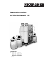
1
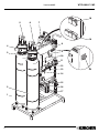
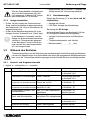
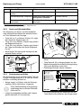
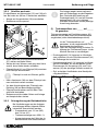
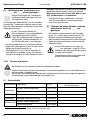
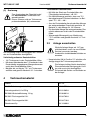
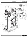
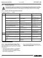
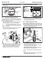
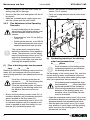
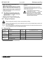
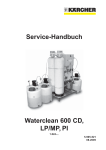
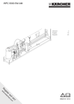
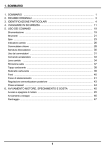
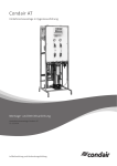
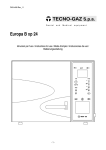
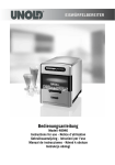
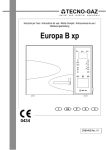
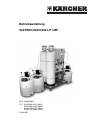
Betriebsanleitung
WATERCLEAN 600 LP / MP
BTA 5.960-505.0
ETL 5.970-054.0 (LP 400V)
5.970-055.0 (MP 400V)
5.970-156.0 (LP 230V)
5.970-157.0 (MP 230V)
A 2011201
WTC 600 LP / MP
Version 06/05
18
5
6
7
19
4
3
8
9
10
11
12
13
14
15
2
16
17
1
2
20
WTC 600 LP / MP
Inhaltsverzeichnis
1
2
3
3.1
3.1.1
3.1.2
3.1.3
3.1.4
3.2
3.2.1
3.2.2
3.2.3
3.2.4
3.2.5
3.2.6
3.3
Sicherheitshinweise................................3
Bestimmungsgemäßer Gebrauch ..........3
Bedienung und Pflege ............................4
Inbetriebnahme ......................................4
Vordruckeinheit ......................................4
Dosierstationen befüllen.........................4
Anlage einschalten .................................5
Betriebsanzeigen....................................5
Während des Betriebes..........................5
Kontroll- und Aufgabenintervalle ............5
Sand- und Aktivkohlefilter.......................6
Dosierpumpe entlüften ...........................6
Feinfilter wechseln..................................7
Feinregulierung der Betriebsdrücke .......7
Chemie anmischen.................................8
Anlage ausschalten ................................9
4
5
6
7
Verbrauchsmaterial ................................9
Störungen.............................................10
Technische Daten ................................11
EG Konformitätserklärung ....................12
Anlagenelemente
1
2
3
4
5
6
7
8
9
10
11
12
13
14
15
16
17
18
19
20
Sicherheitshinweise
Version 06/05
Sandfilter
Aktivkohlefilter
Steuerung Aktivkohlefilter
Steuerung Sandfilter
Manometer Eingangsdruck Sandfilter
Manometer Eingangsdruck Aktivkohlefilter
RO-Filtereinheit
Schaltkasten
Betriebsartenschalter
Bedienfeld
Manometer Pumpendruck
Manometer Konzentratdruck
Konzentratregelventil
Druckregelventil
Manometer Eingangsdruck Feinfilter
Manometer Ausgangsdruck Feinfilter
Feinfiltereinheit
Steckdosen Sand- und Aktivkohlefilter
Steckdosen (3x) für Dosierstationen
Hauptschalter
1
Sicherheitshinweise
Sicherer Betrieb der Anlage ist nur
möglich, wenn Sie die Bedienungsanleitung und die Sicherheitshinweise
vollständig lesen und die darin enthaltenen Anweisungen strikt befolgen.
Trinkwasser
❑ Trinkwasserqualität ist nur bei fristgerechter
Überwachung der Anlage gewährleistet. Beachten Sie die angegebenen Kontrollintervalle.
❑ Lassen Sie die Trinkwasserqualität in regelmäßigen Abständen überprüfen, die gültige Trinkwasserverordnung ist zu beachten.
Chemikalien
❑ Benutzen Sie säurefeste Schutzkleidung (Brille
und Handschuhe).
❑ Lagern Sie die Chemikalien kühl und trocken,
jedoch nicht unter 5 °C.
❑ Bewahren Sie die Chemikalien an einem für
Kinder unzugänglichen Ort auf.
❑ Sorgen Sie für gute Raumbelüftung und eine
Waschgelegenheit.
❑ Stellen Sie eine Augenspülflasche bereit.
Elektrische Anlage
❑ Lassen Sie Arbeiten an der elektrischen Anlage
nur von einer Elektrofachkraft durchführen.
❑ Berühren Sie niemals beschädigte oder durchtrennte Netzkabel, ziehen sie ggf. sofort den
Netzstecker.
❑ Anlage niemals mit beschädigtem Kabel betreiben.
2
Bestimmungsgemäßer
Gebrauch
Die Anlage wird zur Aufbereitung von Oberflächen-, Brunnen- und Flusswasser eingesetzt.
Durch den modularen Aufbau kann in Abhängigkeit der Rohwasserqualität eine Abtrennung von
Trübstoffen, Härtebildnern, Salzen und Bakterien/
Viren sichergestellt werden.
3
Bedienung und Pflege
3
WTC 600 LP / MP
Version 06/05
Bedienung und Pflege
Die Anlage darf nur in Betrieb genommen werden, wenn ein autorisierter KÄRCHER Fachhändler die Anlage aufgebaut, installiert und für den Betrieb vorbereitet hat.
3.1
Inbetriebnahme
Vor der Inbetriebnahme:
• Sicherstellen, dass die Anlage mit der Rohwasserquelle bzw. deren Fördereinrichtung,
z. B. Vordruckeinheit, verbunden ist.
• Sicherstellen, dass das Trinkwasser ungehindert in einen Tank oder eine geeignete nutzerseitige Einrichtung fließen kann.
Das Trinkwasser muss ohne Gegendruck abfließen können. Die Höhendifferenz darf 3 m nicht übersteigen.
3.1.1
i
Falls eine Vordruckeinheit erforderlich
ist, wird diese betriebsbereit vom
Kärcher Servicetechniker installiert.
23
24
25
26
21
4
3.1.2
Dosierstationen befüllen
Ist die Anlage mit einer oder mehreren
Dosierstationen ausgestattet, muss sichergestellt sein, dass diese korrekt
befüllt und angeschlossen sind.
i
• Schutzkleidung anlegen.
• Deckel (27) der Dosierstation (30) öffnen.
Vordruckeinheit
Die Vordruckeinheit besteht aus einer Pumpe
(21) und einem Steuergerät (22). Der Betriebszustand der Pumpe wird mit drei Leuchten angezeigt
• grün (24): betriebsbereit
• gelb (25): Pumpe fördert
• rot (26):
Störung oder Wassermangel
22
• Die Reset Taste (23) startet die Pumpe nach
einer Störung
28
29
27
30
• Entsprechende Chemikalie gemäß Vorgaben
aus Abschnitt 3.2.6 in den Dosierbehälter füllen.
Die Dosierstationen dürfen nicht verwechselt, d. h. mit der falschen Chemikalie befüllt werden.
• Entsprechende Menge chlorfreies Trinkwasser
zugeben.
• Deckel der Dosierstation schließen.
• Den Mischstab (28) bis zum Anschlag aus dem
Dosierbehälter ziehen und wieder zurückschieben.
Diesen Vorgang ca. 5 min lang wiederholen,
bis die Chemikalie vollständig vermischt ist.
WTC 600 LP / MP
War der Dosierbehälter vollständig entleert, hat die Dosierpumpe (29) evtl.
Luft angesaugt. In diesem Fall Pumpe
gemäß Abschnitt 3.2.3 entlüften.
3.1.3
Anlage einschalten
• Prüfen, ob die Pumpen der Dosierstationen,
Sand- und Aktivkohlefilter an den entsprechenden Steckdosen (18 / 19) am Schaltkasten (8)
angeschlossen sind.
• Prüfen ob der Betriebsartenschalter (9) in der
richtigen Position "Automatik" bzw. "Hand" steht.
In der Betriebsart "Automatik" wird die
Anlage von einem externen Schwimmerschalter im Trinkwassertank gesteuert.
In der Betriebsart "Hand" wird die Anlage manuell über den Hauptschalter
ein- und ausgeschaltet.
i
3.2
Bedienung und Pflege
Version 06/05
• Hauptschalter (20) in Position "I" schalten, die
Anlage startet die Trinkwasserproduktion.
3.1.4
Betriebsanzeigen
Display der Steuerung (3 / 4) des Sand- und Aktivkohlefilters:
• Anzeige der Uhrzeit
• LED Zeile: Anzeige des Wochentags
Steuerung der RO-Anlage:
Im zweizeiligen Display am Bedienfeld (10) der
RO-Anlage wird abwechselnd angezeigt:
• Anlagen-/Versionsnummer und Betriebszustand,
• Trinkwassertemperatur und -leitwert,
• Betriebstunden (_ _ _ _ _h _ _min).
Während des Betriebes
Trinkwasserqualität ist nur bei Einhaltung der nachstehenden Kontrollintervalle gewährleistet.
Lassen sich Abweichungen vom Sollzustand nicht durch die angegebenen Maßnahmen beheben, muss die Trinkwasserproduktion gestoppt und der Kärcher Service verständigt werden.
3.2.1
Kontroll- und Aufgabenintervalle
t…täglich, w…wöchentlich, m… monatlich
Intervall Kontrolle/Tätigkeit
t
Füllstand Dosierbehälter
Soll
bei Abweichung
ausreichende Befüllung
auffüllen, Chemie anmischen
s. Abschnitt 3.2.6
Luftblasen in Dosierleitungen keine Luftblasen
Absinken des Trinkwasserflusses bis zu 10%
Feinregulierung,
s. Abschnitt • (1)
ausgehend vom Inbetriebnahmewert
Anstieg des Trinkwasserleitwerts bis zu 10%
Feinregulierung,
s. Abschnitt • (2)
Druckdifferenz Pumpen- und
Konzentratdruck
max. 15% über Inbetriebnah- s. Abschnitt • (3)
medifferenz
Kärcher Service
Betriebszähler
Sand- und Aktivkohlefilter *
Rückspülung hat innerhalb
Kärcher Service
der letzten 24 h stattgefunden
Trinkwasserfluss
ausgehend vom Inbetriebnahmewert
Trinkwasserleitwert
w
Dosierpumpe entlüften,
s. Abschnitt 3.2.3
Druckunterschied Feinfilter
≥ 0,8 bar
Sichtkontrolle Anlage
keine Undichtigkeiten
Feinfilter wechseln
s. Abschnitt 3.2.4
Kärcher Service
Betriebsprotokoll ausfüllen
5
Bedienung und Pflege
Intervall Kontrolle/Tätigkeit
m
WTC 600 LP / MP
Version 06/05
Soll
bei Abweichung
Dosierbehälter reinigen und
spülen
Rohwasserpumpe sichtprüfen keine Beschädigungen/Undichtigkeiten erkennbar
Kärcher Service
Schwimmerschalter im Trink- keine Funktionsstörung
wassertank
erkennbar
Kärcher Service
* zur Umschaltung der Anzeige s. Abschnitt 3.2.2
3.2.2
Sand- und Aktivkohlefilter
33
Die Steuerung von Sand- und Aktivkohlefilter
zeigt während dem Betrieb die aktuelle Uhrzeit
an. Zum Wechseln der Anzeige:
• Taste (32) ca. 5 s drücken, Display (31) zeigt
die Uhrzeit der Regeneration an.
• Taste (32) kurz drücken, Display zeigt Anzahl
der Regenerationen an.
• Taste (32) kurz drücken, Display zeigt Anzahl
der Tage und Stunden seit letzter Regeneration an.
• Nach einiger Zeit springt die Anzeige auf die
aktuelle Uhrzeit zurück.
32
31
34
35
• Die Entlüftungsschraube (34) eine Umdrehung
öffnen.
• Taste Manuell (33) solange drücken, bis das
Medium blasenfrei durch die Entlüftungsleitung
(35) in den Behälter zurück läuft.
• Entlüftungsschraube wieder zudrehen.
production / production
produccion / produzione
3.2.3
Dosierpumpe entlüften
Die Dosierpumpe muss entlüftet werden, falls die
Pumpe Luft angesaugt hat (z. B. weil der Dosierbehälter vollständig entleert ist).
• Anlage stoppt, im Display wird die Störungsmeldung "Motor/Hartwasser" angezeigt.
i
Diese Fehlermeldung wird angezeigt,
unabhängig davon welcher Dosierbehälter leer ist.
• Leeren Dosierbehälter befüllen und Chemie
gemäß Abschnitt 3.2.6 anmischen.
6
fault / default
error / guasto
disinfection / nettoyage
desinfeccion / disinfezione
reject / rejet
evacuation / evacuatione
regeneration / regeneration
regeneracion / rigenerazione
tank full / stockage plein
deposito lleno / serbatoto pieno
RO 1000
ESC
36
• Die Störungsmeldung am Bedienfeld mit der
Taste Return (36) quittieren, die Anlage startet.
WTC 600 LP / MP
3.2.4
Feinfilter wechseln
Druckdifferenz am Manometer (15) und (16) prüfen. Bei mehr als 0,8 bar, Filtereinsatz wechseln:
• Anlage am Hauptschalter (20) ausschalten.
• Rohwasserzufuhr sperren.
15
16
37
i
Die Anlage reagiert etwas zeitverzögert auf Änderungen an den Regelventilen. Deshalb die Einstellung am
Druckregelventil (14) und am Konzentratregelventil (13) nur in kleinen
Schritten durchführen und die jeweilige
Auswirkung abwarten.
(1) Trinkwasserfluss von _____ auf _____
l/h gesunken
38
Trinkwassermenge am Durchflussmesser (42)
ablesen und mit dem Wert bei Inbetriebnahme
vergleichen (siehe Inbetriebnahmeprotokoll).
39
Ist der Trinkwasserfluss auf _____ l/h
gesunken, ist die nachstehende Feinregulierung durchzuführen.
Führt die Feinregulierung zu keiner Erhöhung des Trinkwasserflusses, ist der
Kärcher Service zu verständigen.
40
41
• Eimer unter den Rohwasserentnahmehahn
(37) stellen und Hahn öffnen.
• Warten bis kein Wasser mehr aus dem Hahn
austritt, dann Hahn wieder schließen.
• Filterschlüssel (41) am Filtertopf (40) ansetzen
und Filtertopf abschrauben.
i
Bedienung und Pflege
Version 06/05
• Druckregelventil (14) langsam im Uhrzeigersinn schließen, bis am Durchflussmesser (42)
die Sollmenge fast erreicht ist.
• Konzentratregelventil (13) langsam im Uhrzeigersinn schließen, bis an den beiden Durchflussmessern für Konzentrat (43) und Trinkwasser (42) der jeweilige Sollwert erreicht ist.
• Ggf. an beiden Ventilhebeln eine Nachjustierung durchführen.
Filtertopf ist noch mit Wasser gefüllt.
• Den Filtereinsatz (38) aus dem Filtertopf nehmen und durch neuen ersetzen.
• Vor dem Anschrauben des Filtertopfs den
Dichtring (39) auf Beschädigung prüfen.
• Filtertopf anschrauben und mit dem Filterschlüssel festziehen.
• Rohwasserzufuhr wieder öffnen und Anlage
am Hauptschalter starten.
10
42
43
11
3.2.5
Feinregulierung der Betriebsdrücke
Bei Veränderungen an den Anlageneinstellungen dürfen folgende Werte
keinesfalls überschritten werden:
• Pumpendruck max. 21 bar (MP)
bzw. 14 bar (LP)
• Trinkwassermenge max. 650 l / h
• Konzentratmenge darf Wert der Inbetriebnahme nicht unterschreiten
13
12
14
7
Bedienung und Pflege
(2) Leitfähigkeit des Trinkwassers von
_____ auf _____ µS/cm gestiegen
i
Kleine Erhöhungen der Trinkwasserleitfähigkeit beeinträchtigen die Trinkwasserqualität nicht.
Am Display des Bedienfeldes (10) den aktuellen
Leitwert des Trinkwassers ablesen und mit dem
Wert bei Inbetriebnahme vergleichen (siehe Inbetriebnahmeprotokoll).
Ist der Trinkwasserleitwert auf _____
µS/cm gestiegen, ist die nachstehende
Feinregulierung durchzuführen.
Führt die Feinregulierung zu keiner Absenkung des Trinkwasserleitwerts, ist
der Kärcher Service zu verständigen.
• Konzentratregelventil (13) in kleinen Schritten
gegen den Uhrzeigersinn öffnen, bis die Leitfähigkeit den Sollwert erreicht hat.
• Druckregelventil (14) in kleinen Schritten im
Uhrzeigersinn schließen, bis die Trinkwassermenge im Schauglas (42) den Sollwert erreicht.
3.2.6
WTC 600 LP / MP
Version 06/05
Hinweis: Dabei erhöht sich die Konzentratmenge
gegenüber dem Startwert. Dies ist so gewollt.
Maximalen Druck von 21 bar (MP) bzw. 14 bar
(LP) am Manometer (11) beachten!
• Einstellschritte ggf. wiederholen. Eventuell
wird die ursprüngliche Trinkwassermenge
nicht mehr ganz erreicht.
(3) Differenz zwischen Pumpen- und Konzentratdruck mehr als _____ bar
gestiegen
• Die Werte am Manometer für den Pumpendruck (11) und für den Konzentratdruck (12)
ablesen und den Differenzdruck ermitteln.
• Den aktuellen Differenzdruck mit dem Wert bei
Inbetriebnahme vergleichen (siehe Inbetriebnahmeprotokoll).
Ist der Differenzdruck um mehr als
_____ bar gestiegen, ist die RO-Filtermembran verstopft, eine Nachregelung
ist nicht mehr möglich.
Trinkwasserproduktion einstellen und
Kärcher Service verständigen.
Chemie anmischen
Bei Arbeiten mit Chemikalien immer Schutzkleidung anlegen.
i
Werte für die Dosierung der verschiedenen Chemikalien ergeben sich aus der Rohwasseranalyse und der Anlagenleistung.
Der Kärcher Servicetechniker trägt bei der Inbetriebnahme die für Ihre Anlage erforderlichen
Dosiermengen in die nachstehende Dosiertabelle ein.
(1) Dosiertabelle
Dosierbehälter Chemikalie
Vorchlorung
Art. Nr.
RM 852 Entkeimungsmittel*
Calciumhypochlorit
*
6.291-772.0
6.291-505.0
Vorflockung
Ferrifloc
Anti Scalant
RM 5000 Härtestabilisierung
6.290-991.0
*
6.291-772.0
Nachchlorung
6.294-703.0
RM 852 Entkeimungsmittel
Calciumhypochlorit
*
6.291-505.0
* Diese Chemikalien können jeweils alternativ verwendet werden
8
Dosierung der Chemikalie [ml] pro
10 l Dosierlösung
WTC 600 LP / MP
(2) Dosierung
Zum Anmischen der Chemikalie darf
nur unchloriertes Trinkwasser verwendet werden.
Dieses Wasser wird am Trinkwasserprobenahmehahn (44) entnommen.
44
Teilentleerter Dosierbehälter:
• Mit Hilfe der Skala am Dosierbehälter den
Flüssigkeitsstand ablesen, z.B. 35 l.
• Die Nachfüllmenge ermitteln, dazu von 75 l
den abgelesenen Füllstand abziehen. Im Beispiel: 75 l - 35 l = 40 l.
• Aus der Dosiertabelle die erforderliche Menge
der entsprechenden Chemikalie ermitteln. Im
Beispiel: 4 x die Menge für 10 l Wasser.
• Die ermittelte Menge der entsprechenden Chemikalie abmessen und in den Dosierbehälter
füllen.
• Wassernachfüllmenge bis zur Markierung
"75 l" auffüllen und gemäß Abschnitt 3.1.2 mischen.
3.3
Die Dosierung wird in Abhängigkeit des Füllstandes im Dosierbehälter durchgeführt.
Vollständig entleerter Dosierbehälter:
• 10 l Trinkwasser in den Dosierbehälter füllen.
• Mit einem Messbecher das 7,5-fache der in der
Dosiertabelle angegebenen Menge abmessen
und in den Dosierbehälter füllen.
• Behälter bis zur Marke "75 l" mit Trinkwasser
auffüllen und gemäß Abschnitt 3.1.2 mischen.
4
Verbrauchsmaterial
Version 06/05
Anlage ausschalten
Wird die Anlage länger als 14 Tage
nicht betrieben, muss sie vom Kärcher
Service konserviert werden.
Andernfalls sind bleibende Schäden zu
erwarten.
• Hauptschalter (20) in Position "O" schalten, die
Anlage stoppt die Trinkwasserproduktion.
Die Anlage nie über Nacht abschalten!
Die automatische Reinigung der Vorfilter wird sonst nicht durchgeführt.
Es besteht die Gefahr von Schäden an
der Anlage!
Verbrauchsmaterial
Produkt
Art. Nr.
RM 852 Entkeimungsmittel, 24 kg
6.291-772.0
Calciumhypochlorit, 6 x 870 g
6.291-505.0
RM 5000 Härtestabilisierung, 23 kg
6.290-991.0
RM 5001 Flockungsmittel 10 l
6.294-703.0
RM 5001 Flockungsmittel 60 l
6.294-716.0
Filterelement 5µ
6.414-466.0
9
Störungen
5
WTC 600 LP / MP
Version 06/05
Störungen
Störungen an der RO-Anlage werden am Bedienfeld (10) mit LEDs signalisiert und am Display angezeigt.
i
LED
Bei Auftreten einer Störung wird die Anlage generell abgeschaltet und die Trinkwasserproduktion unterbrochen.
Kann die Störung nicht behoben werden, Trinkwasserproduktion stoppen und Kärcher Service
verständigen.
Bezeichnung/Anzeige
Mögliche Ursache
Behebung
fault
Dosierbehälter leer
Dosierbehälter füllen und anschließend Störung quittieren
Kärcher Service
Sensorsignal fehlt
regeneration
Spülung der Vorfilter aktiv
nicht notwendig, da Anlage
selbsttätig wiedereinschaltet
tank full
Trinkwassertank voll
nicht notwendig, da Anlage
selbsttätig wiedereinschaltet
Schalter kontrollieren,
ggf. Kärcher Service
Schalter defekt
Display
LW-Überschritten
Leitwert des Trinkwassers zu
hoch
Kärcher Service
Hartwasser
Dosierbehälter leer
Dosierbehälter füllen und anschließend Störung quittieren
Druckstörung
Rohwasserdruck zu gering
Rohwasserzufuhr prüfen
• gebäudeseitige Installation
• Vordruckpumpe
• Rohwasserschläuche
Störungen an der Vordruckeinheit werden mit der roten LED (26) auf der Steuereinheit der Vordruckeinheit angezeigt.
Anzeige
Mögliche Ursache
Behebung
rote LED leuchtet
Rohwasserversorgung
unterbrochen
Rohwasserzufluss prüfen und wiederherstellen.
Nach Beheben der Störung, Taste
"Reset" (23) drücken.
10
WTC 600 LP / MP
6
Technische Daten
Version 06/05
Technische Daten
Parameter
WTC 600 LP
Umgebungstemperatur
WTC 600 MP
+1°C - +50°C
Lagerungstemperatur (Auslieferung)
bis -10°C
≤ 100% r.F.
Luftfeuchte
Versorgungsspannung
3 Ph 400 V 50 Hz*
1 Ph 230 V 50 Hz*
Steuerungen Vorfilter: prim/sek.
230 V/12 V 50 Hz
Dosierpumpen
220-240 V 50-60Hz
Elektrische Absicherung
16 A
Elektrischer Anschlusswert
2,2kW
2,2 kW
Effektiver elektrischer Leistungsbedarf
1,5 kW
2,2 kW
Minimale Rohwassertemperatur
+5°C
Maximale Rohwassertemperatur
+35°C
Bezugstemperatur
+15°C
pH-Wert Rohwasser
6-9,5
pH-Wert Reinigungsmittel zur Reinigung der Anlage
3-11
Anlageneingangsdruck
Leistungsbereich
maximale Trinkwasserleistung
2-6 bar
15000 l/Tag (±15%)
650 l/h
Abmessungen: H x B x T
WTC 600 LP/MP
1800 x 660 x 720 mm
WTC 600 LP/MP - A
1800 x 1120 x 720 mm
WTC 600 LP/MP - AM
1800 x 1120 x 720 mm
Gewicht Lieferzustand (ohne Filterfüllungen)
WTC 600 LP/MP
135 kg
WTC 600 LP/MP - A
155 kg
WTC 600 LP/MP - AM
175 kg
Auslegungsbasis für Rohwasser, max.
2000 ppm Salzgehalt
5000 ppm Salzgehalt
* je nach Ausführung derAnlage
11
EG Konformitätserklärung
7
Version 06/05
WTC 600 LP / MP
EG Konformitätserklärung
Hiermit erklären wir, dass die nachfolgend bezeichnete Maschine aufgrund ihrer Konzipierung und Bauart sowie in der von uns in Verkehr gebrachten Ausführung den einschlägigen grundlegenden Sicherheits- und Gesundheitsanforderungen der unten aufgeführten EG-Richtlinien entspricht.
Bei einer nicht mit uns abgestimmten Änderung der Maschine verliert diese Erklärung ihre Gültigkeit.
Produkt:
Trinkwasseraufbereitungsanlage
Typ:
1.024-xxx
Einschlägige EG-Richtlinien:
EG - Maschinenrichtlinie (98/37/EG)
EG - Niederspannungsrichtlinie (73/23/EWG)
geändert durch 93/68/EWG
EG - Richtlinie Elektromagnetische Verträglichkeit
(89/336/EWG) geändert durch 91/263/EWG,
92/31/EWG, 93/68/EWG
Angewandte harmonisierte
Normen:
DIN EN ISO 14971
DIN EN 50178
DIN EN 60 204 – 1
DIN EN 55 011 : 1998
DIN EN 55 014 – 1 : 2000 + A1: 2001 + A2 : 2002
DIN EN 55 014 – 2 : 1997 + A1: 2001
DIN EN 61 000 – 3 – 2 : 2000
DIN EN 61 000 – 3 – 3 : 1995 + A1: 2001
Angewandte nationale
Normen:
Normen: DIN 1988
Winnenden
Es ist durch interne Maßnahmen sichergestellt, dass die Seriengeräte immer den Anforderungen der aktuellen EG-Richtlinien und den
angewandten Normen entsprechen.
Die Unterzeichnenden handeln im Auftrag und mit Vollmacht der Geschäftsführung.
Alfred Kärcher Kommanditgesellschaft. Sitz Winnenden. Registergericht: Waiblingen, HRA 169.
Persönlich haftende Gesellschafterin: Kärcher Reinigungstechnik GmbH. Sitz Winnenden, 2404 Registergericht Waiblingen, HRB
Geschäftsführer: Dr. Bernhard Graf, Hartmut Jenner, Georg Metz
12
5.957-716
06/05
Operating Instructions
WATERCLEAN 600 LP / MP
BTA 5.960-505.0
ETL 5.970-054.0 (LP 400V)
5.970-055.0 (MP 400V)
5.970-156.0 (LP 230V)
5.970-157.0 (MP 230V)
A 2011201
WTC 600 LP / MP
Version 06/05
18
5
6
7
19
4
3
8
9
10
11
12
13
14
15
2
16
17
1
2
20
WTC 600 LP / MP
Contents
1
2
3
3.1
3.1.1
3.1.2
3.1.3
3.1.4
3.2
3.2.1
3.2.2
3.2.3
3.2.4
3.2.5
res
3.2.6
3.3
Safety Notes...........................................3
Intended Use ..........................................3
Maintenance and Care ...........................4
Starting Operation ..................................4
Admission-pressure Unit ........................4
Filling the Metering Stations ...................4
Switching On the Equipment ..................5
Operating Indicators ...............................5
During Operation ....................................5
Control and Corrective Action Intervals..5
Sand and Activated Carbon Filter ..........6
Bleeding the Metering Pump ..................6
Replacing the Fine Filter ........................7
Fine Adjustment of the Operating Pressu...............................................................7
Mixing the Chemicals .............................8
Switching Off the Equipment ..................9
4
5
6
Consumption Materials...........................9
Malfunctions .........................................10
Technical Data .....................................11
7
EU Declaration of Conformity...............12
Equipment Components
1
2
3
4
5
6
7
8
9
10
11
12
13
14
15
16
17
18
19
20
Safety Notes
Version 06/05
Sand filter
Activated carbon filter
Control, activated carbon filter
Control, sand filter
Manometer, sand filter supply pressure
Manometer, activated carbon filter supply
pressure
RO filter unit
Switch box
Operating mode switch
Control panel
Manometer, pump pressure
Manometer, concentrate pressure
Concentrate control valve
Pressure control valve
Manometer, fine filter supply pressure
Manometer, fine filter output pressure
Fine filter unit
Power outlets, sand and activated carbon
filter
Power outlets (3x) for metering stations
Main switch
1
Safety Notes
Safe operation of the equipment is
possible only when the operating instructions and safety notes are read
completely, and the instructions contained therein are strictly followed.
Drinking Water
❑ Drinking water quality is ensured only when the
equipment is controlled within the scheduled
periods. Observe the given control intervals.
❑ Have the drinking water quality checked in regular intervals; the valid drinking water regulations are to be observed.
Chemicals
❑ Wear acid-resistant protective clothing (goggles and gloves).
❑ Store chemicals cool and dry, however, not
below 5 °C.
❑ Keep chemicals at locations not accessible for
children.
❑ Ensure good room ventilation and provide a
washing facility.
❑ Have eye wash bottle readily available.
Electrical Equipment
❑ Work on the electrical equipment is to be carried out only by skilled persons for electrical
work.
❑ Never touch damaged or cut through mains
cables; pull the mains plug immediately, as
required.
❑ Never operate the equipment with a damaged
cable.
2
Intended Use
The equipment is used for conditioning of surface
water, well water and river water.
Depending on the untreated water quality,
the modular set-up enables secure separation
of turbid materials, water hardeners, salts and
bacteria/virus.
3
Maintenance and Care
3
WTC 600 LP / MP
Version 06/05
Maintenance and Care
The equipment may be put into operation only when set-up, installed and prepared for operation by an authorized KÄRCHER specialist dealer.
3.1
Starting Operation
Before starting operation:
• Make sure that the equipment is connected to
the untreated water source and the respective
transporting gear, e. g., admission-pressure
unit.
• Ensure the unrestricted flow of the drinking water
into a tank or a suitable device on the user side.
The drinking water must be able to run
off without counterpressure. The height
difference must not exceed 3 m.
3.1.1
i
In case an admission-pressure unit
is necessary, it will be installed by a
Kärcher service technician.
23
24
25
26
21
4
3.1.2
Filling the Metering Stations
If the system is equipped with one or
more metering stations, it must be ensured that these are correctly filled and
connected.
i
• Put on protective clothing.
• Open the lid (27) of the metering station (30).
Admission-pressure Unit
The admission-pressure unit consists of a
pump (21) and a control device (22). The operating condition of the pump is indicated with three
indicator lights:
• Green (24): Ready for operation
• Yellow (25): Pump delivering
• Red (26):
Malfunction or water low
22
• The reset button (23) starts the pump after failure
28
29
27
30
• Fill the respective chemical into the metering
station according to Section 3.2.6.
The metering stations must not be
mixed up or mistaken, meaning filled
with the wrong chemical.
• Add the corresponding amount of chlorine-free
drinking water.
• Shut the lid of the metering station.
• Pull the mixing rod (28) out of the metering
station to the stop and push back in again.
Repeat this procedure for approx. 5 minutes
until the chemical is completely mixed.
WTC 600 LP / MP
Version 06/05
Maintenance and Care
If the metering container was completely empty, the metering pump (29)
may have possibly drawn in air. In this
case, bleed the air from the pump as
described in Section 3.2.3.
3.1.3
Switching On the Equipment
• Check if the pumps of the metering station,
sand and activated carbon filter are connected
to the respective power outlets (18 / 19) at the
switch box (8).
• Check if the operating mode switch (9) is in the
correct position “Automatic” or “Hand”.
In the “Automatic” operating mode, the
system is controlled via an external float
switch in the drinking water tank.
In the “Hand” operating mode, the system is switched on and off manually via
the main switch.
i
• Switch the main switch (20) to the “I” position;
the system starts the drinking water production.
3.1.4
Operating Indicators
Display of the controls (3 / 4) of the sand and activated carbon filters:
• Display of the time
• LED line: Display of the weekday
Control of the RO system:
The following is alternately indicated on the
two-line display of the control panel (10) of the RO
system:
• Equipment/model No. and operating condition,
• Drinking water temperature and drinking water
conductance value,
• Operating hours (_ _ _ _ _h _ _min).
5
Maintenance and Care
3.2
Version 06/05
WTC 600 LP / MP
During Operation
Drinking water quality is ensured only when the following control intervals are met. In case
deviations from the desired condition can not be eliminated through the measures mentioned,
the drinking water production must be stopped and the Kärcher Service must be notified.
3.2.1
Control and Corrective Action Intervals
d…daily, w…weekly, m… monthly
Interval Check/Activity
d
Target/Purpose
In Case of Deviation
Level, metering container
Sufficient amount/filling
Fill up; mixing chemicals,
see Section 3.2.6
Air bubbles in metering line
No air bubbles
Bleed metering pump,
see Section 3.2.3
Flow of drinking water
Reduction of the drinking water Fine adjustment,
flow up to 10 %
see Section 3.2.5 (1)
based on the operational start-up value
Drinking water conductance value
based on the operational start-up value
Increase of the drinking water Fine adjustment,
conductance value up to 10 % see Section 3.2.5 (2)
Pressure difference between pump 15 % maximum above start-up See Section 3.2.5 (3)
and concentrate pressure
difference
Kärcher Service
Hour meter for sand und activated
carbon filter *
Backwashing has occurred
within the past 24 h
Kärcher Service
Pressure difference, fine filter
≥ 0,8 bar
Replace fine filter,
see Section 3.2.4
Visual inspection of the equipment No leakage
w
Fill out operating log
m
Clean and flush the metering
container
Kärcher Service
Visually check the untreated water No damages/leaks detectable Kärcher Service
pump
Float switch in the drinking water
tank
No operational malfunctions
detectable
Kärcher Service
* for switching over the indication, see Section 3.2.2
3.2.2
Sand and Activated Carbon Filter
During operation, the sand and activated carbon
filter control indicates the actual time. To change
the indication:
• Press button (32) for approx. 5 s; the display
(31) indicates the time of the regeneration.
• Press button (32) briefly; the display indicates
the number of regenerations.
6
• Press the ADVANCE key button briefly; the
display indicates the number of days and hours
since the last regeneration.
WTC 600 LP / MP
Maintenance and Care
Version 06/05
• After a while the indication moves back to the
current time.
• Screw in the bleeding screw again.
production / production
produccion / produzione
fault / default
error / guasto
disinfection / nettoyage
desinfeccion / disinfezione
reject / rejet
evacuation / evacuatione
regeneration / regeneration
regeneracion / rigenerazione
tank full / stockage plein
deposito lleno / serbatoto pieno
32
3.2.3
36
RO 1000
Bleeding the Metering Pump
The metering pump must be bled when the pump
has drawn in air (e. g., because the metering container is completely empty).
• The system stops; the “Motor/hard water“ malfunction indication is shown in the display.
i
ESC
31
This malfunction indication is shown independent of which metering container
is empty.
• Fill the empty metering container and mix the
chemicals according to Section 3.2.6.
• On the control panel, acknowledge the malfunction indication with the RETURN key button (36); the system starts.
3.2.4
Replacing the Fine Filter
Check the pressure difference at manometers (15)
and (16). Replace the filter insert when over 0.8 bar:
• Switch off the equipment at the main switch (20).
• Stop the untreated water supply.
15
16
33
37
38
39
34
35
40
41
• Unscrew the bleeding screw (34) by one turn.
• Press the MANUAL pushbutton (33) until the
medium flows without bubbles through the
bleeding line (35) back into the container.
• Place a bucket under the untreated water drain
cock (37) and open the cock.
• Wait until no more water emerges out of the
cock, then shut the cock again.
• Attach the filter wrench (41) to the filter bowl
(40) and screw off the filter bowl.
i
The filter bowl is still filled with water.
• Remove the filter insert (38) from the filter bowl
and replace with a new one.
7
Maintenance and Care
• Before screwing on the filter bowl, check the
sealing ring (39) for damage.
• Screw on the filter bowl and tighten with the filter wrench.
• Open the untreated water supply again and
start the system with the main switch.
3.2.5
The system reacts somewhat timedelayed to alterations of the regulation
valves. Therefore carry out the adjustment at the pressure control valve (14)
and at the concentrate control valve
(13) only in small steps, and wait until
checking the respective effect.
(1) Flow of drinking water has decreased
from _____ to _____ l/h
Read off the amount of drinking water at the flow
meter (42) and compare with the value taken
when starting operation (see operational start-up
record).
If the flow of drinking water has decreased to _____ l/h , the following fine
adjustment is to be carried out.
If the fine adjustment does not lead to
an increase in the drinking water flow,
the Kärcher Service must be contacted.
• Slowly shut the pressure control valve (14) in
clockwise direction until the desired amount is
almost reached at the flow meter (42).
• Slowly shut the concentrate control valve (13)
in clockwise direction until the respective set
value is reached on both flow meters for concentrate (43) and drinking water (42).
8
Notice: The quantity of concentrate will increase. This is correct.
• Carry out a readjustment on both valve levers,
if required.
Fine Adjustment of the Operating
Pressures
In case of alterations to the system
adjustments, the following values must
not be exceeded under any circumstances:
• Pump pressure, max. 21 bar (MP) or
14 bar (LP)
• Drinking water amount, max. 650 l/h
• The concentrate amount must not exceed the operational start-up value
i
WTC 600 LP / MP
Version 06/05
10
42
43
11
13
12
14
(2) Conducting capacity of the drinking
water has increased from _____
to _____ µS/cm
i
Small increases of the drinking water
conducting capacity do not influence
the drinking water quality.
On the display of the control panel (10), read the
current drinking water conductance value and
compare with the value taken when starting operation (see operational start-up record).
If the drinking water conductance value
has increased to _____ µS/cm, the following fine adjustment is to be carried out.
If the fine adjustment does not lead to a
decrease of the drinking water conductance value, the Kärcher Service
must be contacted.
• Open the concentrate control valve (13) in counterclockwise direction in small steps until the conductance capacity has reached the set value.
• Shut the pressure control valve (14) in clockwise direction in small steps until the drinking
water amount in the viewing glass (42) has
reached the set value.
WTC 600 LP / MP
Notice: The amount of concentrate will increase. This is correct.
Observe the maximum pressure of 21 bar
(MP) or 14 bar (LP) at the manometer (11)!
• Repeat the adjustment steps, if required. The
original drinking water amount may possibly
not quite be reached.
pressure (12), and determine the differential
pressure.
• Compare the differential pressure with the
value taken when starting operation (see operational start-up record).
(3) The difference between pump and
concentrate pressure has increased
by more than _____ bar
• Read the values at the manometer for the
pump pressure (11) and for the concentrate
3.2.6
Maintenance and Care
Version 06/05
If the differential pressure has increased by more than _____ bar, then
the RO filter membrane is clogged.
Readjustment is no longer possible.
Stop the drinking water production and
notify the Kärcher Service.
Mixing the Chemicals
When working with chemicals, always wear protective clothing.
i
Values for the metering of the various chemicals result from the untreated water analysis and
the system capacity.
Upon starting operation, the Kärcher service technician enters the required metering amounts
for your equipment into the following metering table.
(1) Metering Table
Metering
Container
Prechlorination
Chemical
Item No.
Metered Amount of the Chemical [ml] per
10 l Metering Solution
RM 852 sterilization agent * 6.291-772.0
Chlorinated lime *
Pre-flocculation Ferrifloc
6.291-505.0
6.294-703.0
Anti Scalant
RM 5000 hardness stabilizer 6.290-991.0
Post
chlorination
RM 852 sterilization agent * 6.291-772.0
Chlorinated lime *
6.291-505.0
* These chemicals can each be used alternatively
9
Consumption Materials
(2) Metered Addition
For mixing of the chemical, only unchlorinated drinking water may be
used.
This water is taken from the drinking
water sampling valve (44).
44
The metered addition is carried out dependent of
the level in the metering container.
Completely emptied metering container:
• Fill 10 l of drinking water into the metering container.
• With a measuring cup, measure the 7.5 -fold
amount mentioned in the “10 Liter Water” column of the respective chemical and fill into the
container.
• Fill the container with drinking water to the “75
l” mark and mix according to Section 3.1.2.
4
WTC 600 LP / MP
Version 06/05
Partially emptied metering container:
• Read off the level of the fluid with help of the
scale at the metering container, e. g., 35 l.
• Determine the quantity to be refilled by subtracting the read level from the 75 l.
Example: 75 l - 35 l = 40 l.
• Determine the required amount of the respective chemical from the metering table.
Example: 4 x the amount for 10 l water.
• Measure the determined amount of the respective chemical and fill into the container.
• Refill amount of water to the “75 l” mark and
mix in accordance with Section 3.1.2.
3.3
Switching Off the Equipment
If the equipment is not operated for
periods exceeding 14 days, it must be
preserved by the Kärcher Service.
Otherwise permanent damage must be
expected.
• Switch the main switch (20) to the “O” position;
the equipment stops the drinking water production.
Never switch off the equipment overnight! Otherwise the automatic cleaning of the pre-filter is not carried
through. Danger of damage to the
equipment is given!
Consumption Materials
Product
Item No.
RM 852 sterilization agent 24 kg
6.291-772.0
Chlorinated lime 6 x 870 g
6.291-505.0
RM 5000 hardness stabilizer 23 kg
6.290-991.0
RM 5001 flocculation agent 10 l
6.294-703.0
RM 5001 flocculation agent 60 l
6.294-716.0
Filter element 5µ
6.414-466.0
10
WTC 600 LP / MP
5
Malfunctions
Version 06/05
Malfunctions
Malfunctions of the RO system are signaled with LEDs at the control panel (10) and indicated at the
display.
i
In case of a malfunction, the system is generally switched off and the drinking water production
is interrupted.
If the malfunction can not be corrected, stop the drinking water production and notify the
Kärcher Service.
LED
Designation/Indication Possible Cause
Corrective Action
fault
Fill metering container and acknowledge malfunction afterwards
Kärcher Service
Metering container empty
Sensor signal missing
regeneration
Flushing of the pre-filter is active Not required, as the system
switches on again automatically
tank full
Drinking water tank full
Switch defective
Display
Not required, as the system
switches on again automatically
Check switch;
if required, Kärcher Service
CV exceeded
Conductance value of the
drinking water too high
Kärcher Service
Hard water
Metering container empty
Fill metering container and
acknowledge malfunction afterwards
Pressure malfunction
Pressure of untreated water
too low
Check untreated water supply
• Installation on building side
• Admission-pressure pump
• Hoses for untreated water
Malfunctions on the admission-pressure unit are indicated with the red LED (26) on the control unit of
the admission-pressure unit.
Indication
Possible Cause
Corrective Action
Red LED lights
Untreated water supply
disconnected
Check and reestablish the untreated
water supply.
After correcting the malfunction,
press the “Reset” pushbutton (23).
11
Technical Data
6
WTC 600 LP / MP
Version 06/05
Technical Data
Parameter
WTC 600 LP
Ambient temperature
+1 °C – +50 °C
Storage temperature (upon delivery)
to –10 °C
Humidity
<100 % r.F.
3*400 V 50 Hz *
1*230 V 50 Hz *
Supply voltage
Pre-filter controls: prim./sec.
Metering pumps
WTC 600 MP
230 V/12 V 50 Hz
220 – 240 V 50 – 60Hz
Electrical protection
16 A
Connected load
2.2kW
2.2 kW
Effective power consumtion
1.5 kW
2.2 kW
Minimum temperature of untreated water
+5 °C
Maximum temperature of untreated water
+35 °C
Reference temperature
+15 °C
pH-value of untreated water
6 – 9.5
pH-value cleaning agent for cleaning the equipment
3 – 11
System intake pressure
Capacity range
2 – 6 bar
15000 l/day (±15 %)
Maximum drinking water supply
650 l/h
Dimensions: H x W x D
WTC 600 LP/MP
1800 x 660 x 720 mm
WTC 600 LP/MP - A
1800 x 1120 x 720 mm
WTC 600 LP/MP - AM
1800 x 1120 x 720 mm
Weight, in delivery condition
WTC 600 LP/MP
135 kg
WTC 600 LP/MP - A
155 kg
WTC 600 LP/MP - AM
175 kg
Designed for untreated water based on a
maximum salt content of
* depending on supply by the customer
12
2000 ppm
5000 ppm
WTC 600 LP / MP
7
Version 06/05
EU Declaration of Conformity
EU Declaration of Conformity
We hereby declare that the equipment described below conforms to the relevant fundamental safety and
health requirements of the appropriate EU Directive, both in its basic design and construction as well as
in the version marketed by us.
This declaration will cease to be valid if any modifications are made to the machine without our express
approval.
Product:
Water treatment plant
Model:
1.024-xxx
Relevant EU Directives:
EU - Machinery Directive (98/37/EU)
EU - Low-Voltage Equipment Directive (73/23/EEC)
amended by 93/68/EEC
EU - Directive on Electromagnetic Compatibility (89/336/EEC)
amended by 91/263/EEC, 92/31/EEC, 93/68/EEC
Harmonized standards applied:
DIN EN ISO 14971
DIN EN 50178
DIN EN 60 204 – 1
DIN EN 55 011 : 1998
DIN EN 55 014 – 1 : 2000 + A1: 2001 + A2 : 2002
DIN EN 55 014 – 2 : 1997 + A1: 2001
DIN EN 61 000 – 3 – 2 : 2000
DIN EN 61 000 – 3 – 3 : 1995 + A1: 2001
National standards applied:
DIN 1988
Winnenden
Appropriate internal measures have been taken to ensure that series-production units conform at all times to the requirements of current
EU Directives and relevant standards.
The signatories are empowered to represent and act on behalf of the company management.
Alfred Kärcher Kommanditgesellschaft. Sitz Winnenden. Registergericht: Waiblingen, HRA 169.
Persönlich haftende Gesellschafterin: Kärcher Reinigungstechnik GmbH. Sitz Winnenden, 2404 Registergericht Waiblingen, HRB
Geschäftsführer: Dr. Bernhard Graf, Hartmut Jenner, Georg Metz
5.957-716
06/05
13