1
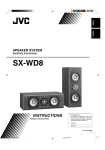
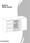
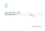
SX-DW55
POWERED SUBWOOFER
INSTRUCTIONS
Thank you for purchasing a JVC speaker.
Before you begin using it, please read the instructions carefully to be sure you get
the best possible performance. If you have any questions, consult your JVC dealer.
LVT1361-004A
[B]
© 2005 Victor Company of Japan, Limited
— SAFETY INSTRUCTIONS —
“SOME DOS AND DON’TS ON THE SAFE USE OF EQUIPMENT”
This equipment has been designed and manufactured to meet international
safety standards but, like any electrical equipment, care must be taken if you
are to obtain the best results and safety is to be assured.
Do read the operating instructions before you attempt to use the equipment.
Do ensure that all electrical connections (including the mains plug, extension
leads and interconnections between pieces of equipment) are properly made
and in accordance with the manufacturer’s instructions.
Switch off and withdraw the mains plug when making or changing connections.
Do consult your dealer if you are ever in doubt about the installation, operation
or safety of your equipment.
Do be careful with glass panels or doors on equipment.
DON’T continue to operate the equipment if you are in any doubt about it
working normally, or if it is damaged in any way—switch off, withdraw the mains
plug and consult your dealer.
DON’T remove any fixed cover as this may expose dangerous voltages.
DON’T leave equipment switched on when it is unattended unless it is specifically stated that it is
designed for unattended operation or has a standby mode.
Switch off using the switch on the equipment and make sure that your family know how to do this.
Special arrangements may need to be made for infirm of handicapped people.
DON’T use equipment such as personal stereos or radios so that you are distracted
from the requirements of traffic safety. It is illegal to watch television whilst driving.
DON’T listen to headphones at high volume as such use can permanently
damage your hearing.
DON’T obstruct the ventilation of the equipment, for example with curtains or soft furnishing.
Overheating will cause damage and shorten the life of the equipment.
DON’T use makeshift stands and NEVER fix legs with wood screws—to ensure
complete safety always fit the manufacturer’s approved stand or legs with the
fixings provided according to the instructions.
DON’T allow electrical equipment to be exposed to rain or moisture.
ABOVE ALL.
– NEVER let anyone, especially children, push anything into holes, slots or any
other opening in the case—this could result in a fatal electrical shock.
– NEVER guess or take chances with electrical equipment of any kind—it is
better to be safe than sorry!
IMPORTANT for the U.K.
DO NOT cut off the mains plug from this equipment. If the plug fitted is not
suitable for the power points in your home or the cable is too short to reach
a power point, then obtain an appropriate safety approved extension lead or
consult your dealer.
BE SURE to replace the fuse only with an identical approved type, as originally fitted.
If nonetheless the mains plug is cut off ensure to remove the fuse and dispose of the plug
immediately, to avoid a possible shock hazard by inadvertent connection to the mains supply.
If this product is not supplied fitted with a mains plug then follow the
instructions given below:
0705NSMSANHCE
EN
o Caution—Proper Ventilation
IMPORTANT:
DO NOT make any connection to the terminal which is marked with the letter E
or by the safety earth symbol or colored green or green-and-yellow.
The wires in the mains lead on this product are colored in accordance with the following code:
Blue :
Neutral
Brown : Live
As these colors may not correspond with the colored markings identifying the
terminals in your plug proceed as follows:
The wire which is colored blue must be connected to the terminal which is marked
with the letter N or colored black.
The wire which is colored brown must be connected to the terminal which is
marked with the letter L or colored red.
IF IN DOUBT - CONSULT A COMPETENT ELECTRICIAN.
To avoid risk of electric shock and fire, and to prevent damage, locate the
apparatus as follows:
1. Front:
No obstructions and open spacing.
2. Sides/ Top/ Back: No obstructions should be placed in the areas shown by
the dimensions below.
3. Bottom:
Place on the level surface. Maintain an adequate air path for
ventilation by placing on a stand with a height of 10 cm or
more.
Front View
Side View
Front
20 cm
20 cm
15 cm
20 cm
15 cm
Warnings, Cautions and Others
o Caution!
To avoid personal injury or accidentally dropping the unit, have
two persons unpack, carry, and install the unit.
21 kg
To reduce the risk of electrical shocks, fire, etc.:
1. Do not remove screws, covers or cabinet.
2. Do not expose this appliance to rain or moisture.
10 cm
o Precautions for installation
o Caution—POWER switch
This apparatus is provided with POWER switch to minimize power consumption for
safe use. Therefore,
1. Before doing initial settings, complete all the connections required, connect the
mains plug into the wall outlet, then set the POWER switch to ON [ B ].
The power lamp lights in green or red.
2. Press the AUTO ON / STANDBY switch to the ON [ A ] position.
• If no sound comes in for a few minutes, the unit enters standby mode.
The power lamp lights in red.
• If the unit detects incoming signals, the unit starts operating. The power lamp
lights in green.
3. Press out the AUTO ON / STANDBY switch to set it to the [ B ] CANCEL
position. The power lamp lights in green.
4. When not in use, set the POWER switch to OFF [ A ].
This disconnects the main line.
o Cautions
• Do not block the ventilation openings or holes. (If the ventilation openings or holes
are blocked by a newspaper or cloth, etc., the heat may not be able to get out.)
• Do not place any naked flame sources, such as lighted candles, on the apparatus.
• When discarding batteries, environmental problems must be considered and local
rules or laws governing the disposal of these batteries must be followed strictly.
• Do not expose this apparatus to rain, moisture, dripping or splashing and that no
objects filled with liquids, such as vases, shall be placed on the apparatus.
• To prevent deformation or discoloration of the cabinet, do not install the unit
where it is exposed to direct sunlight or high humidity, and avoid installation near
air conditioning outlets.
• Speaker vibrations may cause howling. Place the unit as far away from the player
as possible.
• Take the occurrence of earthquakes or other physical shocks into consideration
when selecting the installation place, and secure the unit thoroughly.
• Tuner reception may become noisy or hissing if this unit is installed nearby the
tuner. In this case, leave a more distance between the tuner and this unit or use
an outdoor antenna for better tuner reception without interference from this unit.
• The unit is magnetically shielded to avoid color distortions on TVs. However,
if not installed properly, it may cause color distortions. So, pay attention to the
following when installing the unit.
– When placing this unit near a TV set, turn off the TV’s main power switch or
unplug it before installing this unit.
Then wait at least 30 minutes before turning on the TV’s main power switch again.
Some TVs may still be affected even though you have followed the above. If this
happens, move this unit away from the TV.
• When the TV screen shakes, move this unit away from the TV to find a position
where the screen doesn’t shake and then set the unit there.
Connections (Make all connections before plugging in this unit.)
Checking Your Amplifier
Before connecting this unit to your amplifier (or receiver), check what types of
connecting terminals your amplifier has.
Follow the instructions below to find a proper connection method for your
equipment.
• Illustrations of jacks and terminals in this manual may be different from the ones
actually used for your amplifier. The illustrations are of the most used type.
CAUTION
Before connecting this unit to the amplifier (or receiver), observe the following carefully.
• Turn off the amplifier.
• DO NOT use the INPUT 1 (LOW LEVEL) and INPUT 2 (HIGH LEVEL) terminals on the rear of this unit at the same time; otherwise, noise will be heard and may
damage the unit.
• DO NOT connect this unit to the REC OUT jacks of your amplifier.
First check whether your amplifier has a subwoofer output jack.
Next check whether your amplifier has line output jacks.
It is usually named and printed as the “SUBWOOFER OUT” or “SUBWOOFER.”
They are usually named and printed as “LINE OUT” or “LINE OUTPUT.”
If you find it on your amplifier, follow Connecting Method A.
Follow Connecting Method C.
If you find them on your amplifier, follow Connecting Method B.
This connection can be used for two amplifiers, by connecting the front speaker
terminals of the amplifier (usually named and printed as “FRONT SPEAKERS” or
“MAIN SPEAKERS”).
FRONT SPEAKERS
LINE OUT
SUBWOOFER
OUT
L
If you cannot
find any
1
If you cannot
find any
2
R
o Connecting Method A
RIGHT
LEFT
o Connecting Method C
o Connecting Method B
Preparation:
Preparation:
Preparation:
Use the supplied monaural audio cord.
Purchase a stereo audio cord at an audio
shop or electric shop.
Purchase speaker cords at an audio shop
or electric shop.
If your amplifier has only a monaural line output (MONO) jack, connect it to the
MONO jack of the INPUT 1 (LOW LEVEL) terminal.
FRONT SPEAKERS
Main (Front) Speakers
(not supplied)
Main (Front) Speakers
(not supplied)
1
2
RIGHT
LINE OUT
LEFT
Your Amplifier
L
SUBWOOFER
OUT
Speaker cords
(not supplied)
R
Stereo audio cord
(not supplied)
Monaural audio cord
(supplied)
RIGHT
CUT OFF
FREQUENCY
VOLUME
MAX
MIN
200Hz
50Hz
PHASE
POWER
AUTO ON/
STANDBY
ON
NORMAL
REVERSE
ON
CANCEL
INPUT 2
(HIGH LEVEL)
RIGHT
LEFT
RIGHT
OFF
Main (Front) Speakers
(not supplied)
Your Amplifier
Your Amplifier
RIGHT
LEFT
INPUT 1
(LOW LEVEL)
VOLUME
MAX
MIN
CUT OFF
FREQUENCY
200Hz
50Hz
PHASE
POWER
AUTO ON/
STANDBY
ON
NORMAL
REVERSE
MONO
LEFT
ON
CANCEL
INPUT 2
(HIGH LEVEL)
RIGHT
LEFT
(LOW LEVEL)
OUTPUT
RIGHT
INPUT 1
(LOW LEVEL)
OFF
Left speaker
Right speaker
Speaker cords
(not supplied)
LEFT
INPUT 1
(LOW LEVEL)
MONO
LEFT
INPUT 2
(HIGH LEVEL)
RIGHT
LEFT
(LOW LEVEL)
OUTPUT
INPUT 1
(LOW LEVEL)
MONO
(LOW LEVEL)
OUTPUT
RIGHT
LEFT
MONO
(LOW LEVEL)
OUTPUT
RIGHT
LEFT
To an AC outlet
To an AC outlet
SX-DW55
SX-DW55
VOLUME
MAX
MIN
CUT OFF
FREQUENCY
200Hz
50Hz
PHASE
POWER
AUTO ON/
STANDBY
ON
NORMAL
REVERSE
Memo
You can connect two or more subwoofer as desired with this
terminal.
INPUT 2
(HIGH LEVEL)
RIGHT
LEFT
(LOW LEVEL)
OUTPUT
RIGHT
OFF
ON
CANCEL
RIGHT
LEFT
LEFT
INPUT 1
(LOW LEVEL)
MONO
(LOW LEVEL)
OUTPUT
RIGHT
LEFT
To an AC outlet
SX-DW55
SX-DW55_57[B]_En_A3.indd 2
7/7/2005 1:55:31 PM
Operations
Changing the Phase—PHASE D
Turning On the Power—POWER A
Press the ON [ B ] portion of the POWER button.
The main power turns on and the power lamp in the front panel lights in green.
• The power lamp lights in red when the Auto On/ Standby places the unit into
standby mode.
FRONT
POWER
To completely cut off the power to this unit
Press the OFF [ A ] portion of the POWER button.
This will disconnect the mains lead.
ON
You can change the sound phase to match your preference.
Select either “NORMAL” or “REVERSE” to obtain a better bass sound.
Press in or out the PHASE button to select either the NORMAL position or
the REVERSE position.
PHASE
OFF
NORMAL
REVERSE
• NORMAL : Normally select this.
• REVERSE : Select this when you feel the bass sound is better with this mode
rather than with “NORMAL.”
Adjusting the Volume—VOLUME B
Adjust the volume output level through this unit while comparing with the sounds
coming out of the main (front) speakers.
• Once you have adjusted the volume output level of this unit, you do not need to
adjust it each time you use this unit.
Adjusting the volume level on the connected amplifier will also adjust the volume
level through this unit.
VOLUME
1. Turn the VOLUME knob to the MIN position.
MAX
MIN
Operating the Unit Automatically According to the Incoming Signals
—AUTO ON/STANDBY E
By using this function, this unit automatically enters standby mode even though the
POWER switch is turned ON [ B ].
Press the AUTO ON/STANDBY button to the A ON position.
AUTO ON/
STANDBY
Power lamp
ON
CANCEL
2. Turn on the connected amplifier and start playing a source.
REAR
Playback sounds come out of the main (front) speakers and this unit.
3. Adjust the VOLUME knob to obtain a well-balanced sound level with that
of the main (front) speakers.
VOLUME
MAX
MIN
• If no sound comes in for about 10 minutes, the unit automatically enters standby
mode. The power lamp lights in red. Then if the unit detects incoming signals,
this unit starts operating automatically (the power lamp now lights in green).
If Auto On/Standby does not work correctly (see “Memo” below), press out the
AUTO ON/STANDBY button to set it to the B CANCEL position. Auto On/Standby
is canceled.
AUTO ON/
STANDBY
ON
CANCEL
Caution
If the volume is set at a high level before starting play, the sudden blast of sound
energy can permanently damage your hearing and/or ruin your speakers.
Adjusting the Crossover Frequency
—CUT OFF FREQUENCY C
VOLUME
MAX
MIN
CUT OFF
FREQUENCY
200Hz
50Hz
B
PHASE
VOLUME
NORMAL
REVERSE
POWER
AUTO ON/
STANDBY
ON
A
OFF
POWER
ON
CANCEL
C
CUT OFF
FREQUENCY
E
INPUT 2
(HIGH LEVEL)
RIGHT
LEFT
D
RIGHT
PHASE
AUTO ON/
STANDBY
LEFT
INPUT 1
(LOW LEVEL)
MONO
(LOW LEVEL)
OUTPUT
RIGHT
Memo
When the volume level of the amplifier is so low or the incoming signals are
so weak that this unit cannot detect sounds, Auto On/Standby may not work
correctly.
• This unit may enter standby mode even though signals are coming in.
• This unit may not start operating after entering standby mode, even though
signals start coming in.
You can adjust the crossover frequency to determine the bass sound level this unit
handles.
• Once it is set, only the sounds below the frequency come out of the built-in
speaker.
Turn the CUT OFF FREQUENCY knob to obtain the best matching crossover
frequency with your main speakers.
Adjust the frequency (50 Hz to 200 Hz) while listening to playback sound coming
out of both the main speakers and this unit.
CUT OFF
FREQUENCY
200Hz
LEFT
50Hz
• If your main speakers can reproduce the bass sound well, adjust the frequency
at a lower level.
• If you feel bass sounds are not sufficient, adjust the frequency at a higher level.
Additional Information
Speaker layout
To obtain the best possible sound from your unit:
– Place a subwoofer wherever you like since bass sound is nondirectional.
Normally place it in front of you.
– Place all the main speakers at the same distance from the listening position.
– Be sure to place the powered subwoofer to the TV’s right. If you place the
powered subwoofer to the TV’s left, keep sufficient distance between them to
prevent the TV from appearing mottled.
Center speaker
Front left
speaker
Troubleshooting
Use this chart to help you solve daily operational problems. If there is any problem you cannot solve, contact your dealer.
Symptom
o Precautions for Daily Use
Action
Power does not come on.
Is the unit plugged in?
Plug the AC power cord firmly into the AC outlet.
Auto On/Standby does not function correctly.
Signals are too weak or volume level is too low.
This is not a malfunction. If this happens, cancel
Auto On/Standby.
No sound is heard.
Is the VOLUME knob turned to the MIN position?
Turn the VOLUME knob until a suitable volume is
found.
Connections are incorrect, or loose.
Check the connections. If incorrect, redo the
corrections.
Audio signals through the amplifier are extremely
weak.
Increase the volume level on the amplifier.
Sounds fluctuate (suddenly become loud or soft).
The built-in protective circuit is working.
Lower the volume level on the amplifier so that the
symptom will not occur.
Suddenly no sound comes out.
– the power lamp lights in red.
The VOLUME knob on the rear is set to a very high
level.
Turn down the volume, then turn off and on this
unit.
Suddenly no sound comes out.
– the power lamp still lights in green.
The volume of the playback source is too high.
Turn down the volume of the playback source,
turn off and on the source, then adjust the volume
properly on the source.
Front right
speaker
Powered
subwoofer
Surround left
speaker
Possible Cause
Surround right
speaker
• To maintain the appearance of the unit
Wipe with a dry, soft cloth if the cabinet or control panel should become dirty.
If very dirty, apply a small amount of water or neutral detergent to the cloth and
wipe clean. Then wipe with a dry cloth.
• To improve the sound field
If the speakers are facing a solid wall or glass door, etc., it is recommended to
furnish the wall with materials that absorb sounds, for example by hanging up
thick curtains, to prevent reflections and standing waves.
Specifications
Type
: Powered Subwoofer
Bass-reflex type, (magnetically shielded type)
Speaker unit
: 25.0 cm cone (× 1)
Frequency range
: 25 Hz to 200 Hz
Input impedance
: 50 kK (LOW LEVEL)
470 K (HIGH LEVEL)
Input terminals
: INPUT 1 (LOW LEVEL)
INPUT 2 (HIGH LEVEL)
Power requirements
: AC 230 V H, 50 Hz
Output power of built-in amp : 240 W (50 Hz, 4 K, 10 % THD)
Power consumption
: 60 W
Dimensions
: (W/H/D) 254 × 481 × 430.5 mm
Mass
: 17.3 kg
Accessories
: Monaural audio cord (× 1)
If the item mentioned above is missing,
contact your dealer immediately.
Design and specifications subject to change without notice.
SX-DW55_57[B]_En_A3.indd 3
7/7/2005 1:55:33 PM
SX-DW55
POWERED SUBWOOFER
Operations
Thank you for purchasing a JVC speaker.
Before you begin using it, please read the instructions carefully to be sure you get
the best possible performance. If you have any questions, consult your JVC dealer.
LVT1361-007A
[US]
© 2005 Victor Company of Japan, Limited
Changing the Phase—PHASE D
Turning On the Power—POWER A
INSTRUCTIONS
0705NSMSANHCE
EN
Press the ON [ B ] portion of the POWER button.
The main power turns on and the power lamp in the front panel lights in green.
• The power lamp lights in red when the Auto On/ Standby places the unit into
standby mode.
FRONT
POWER
Warnings, Cautions and Others
o Caution!
To avoid personal injury or accidentally dropping the unit, have
two persons unpack, carry, and install the unit.
21 kg
To reduce the risk of electrical shocks, fire, etc.:
1. Do not remove screws, covers or cabinet.
2. Do not expose this appliance to rain or moisture.
1. Front:
No obstructions and open spacing.
2. Sides/ Top/ Back: No obstructions should be placed in the areas shown by the
dimensions below.
3. Bottom:
Place on the level surface. Maintain an adequate air path for
ventilation by placing on a stand with a height of 10 cm or
more.
Front View
Side View
Front
20 cm
15 cm
o Caution—POWER switch
This apparatus is provided with POWER switch to minimize power consumption
for safe use. Therefore,
1. Before doing initial settings, complete all the connections required, connect
the mains plug into the wall outlet, then set the POWER switch to ON [ B ].
The power lamp lights in green or red.
2. Press the AUTO ON / STANDBY switch to the ON [ A ] position.
• If no sound comes in for a few minutes, the unit enters standby mode.
The power lamp lights in red.
• If the unit detects incoming signals, the unit starts operating. The power
lamp lights in green.
3. Press out the AUTO ON / STANDBY switch to set it to the [ B ] CANCEL
position. The power lamp lights in green.
4. When not in use, set the POWER switch to OFF [ A ].
This disconnects the main line.
o Cautions
• Do not block the ventilation openings or holes. (If the ventilation openings or
holes are blocked by a newspaper or cloth, etc., the heat may not be able to get
out.)
• Do not place any naked flame sources, such as lighted candles, on the
apparatus.
• When discarding batteries, environmental problems must be considered and
local rules or laws governing the disposal of these batteries must be followed
strictly.
• Do not expose this apparatus to rain, moisture, dripping or splashing and that
no objects filled with liquids, such as vases, shall be placed on the apparatus.
o Caution—Proper Ventilation
To avoid risk of electric shock and fire, and to prevent damage, locate the
apparatus as follows:
20 cm
20 cm
15 cm
10 cm
o MAINS (AC) LINE INSTRUCTION
(not applicable for Europe, U.S.A., Canada, Australia, and U.K.)
IMPORTANT for mains (AC) line
BEFORE PLUGGING IN, do check that your mains (AC) line voltage corresponds
with the position of the voltage selector switch provided on the outside of this
equipment and, if different, reset the voltage selector switch, to prevent from a
damage or risk of fire/electric shock.
To completely cut off the power to this unit
Press the OFF [ A ] portion of the POWER button.
This will disconnect the mains lead.
CAUTION
DO NOT plug the power cord of the powered subwoofer before
setting the VOLTAGE SELECTOR switch to the correct voltage.
o Precautions for installation
• To prevent deformation or discoloration of the cabinet, do not install the unit
where it is exposed to direct sunlight or high humidity, and avoid installation
near air conditioning outlets.
• Speaker vibrations may cause howling. Place the unit as far away from the player as
possible.
• Take the occurrence of earthquakes or other physical shocks into consideration
when selecting the installation place, and secure the unit thoroughly.
• Tuner reception may become noisy or hissing if this unit is installed nearby the
tuner. In this case, leave a more distance between the tuner and this unit or
use an outdoor antenna for better tuner reception without interference from this
unit.
• The unit is magnetically shielded to avoid color distortions on TVs. However,
if not installed properly, it may cause color distortions. So, pay attention to the
following when installing the unit.
– When placing this unit near a TV set, turn off the TV’s main power switch or
unplug it before installing this unit.
Then wait at least 30 minutes before turning on the TV’s main power switch
again.
Some TVs may still be affected even though you have followed the above. If this
happens, move this unit away from the TV.
• When the TV screen shakes, move this unit away from the TV to find a position
where the screen doesn’t shake and then set the unit there.
Before connecting this unit to your amplifier (or receiver), check what types of
connecting terminals your amplifier has.
Follow the instructions below to find a proper connection method for your
equipment.
• Illustrations of jacks and terminals in this manual may be different from the
ones actually used for your amplifier. The illustrations are of the most used
type.
First check whether your amplifier has a subwoofer output jack.
It is usually named and printed as the “SUBWOOFER OUT” or “SUBWOOFER.”
If you find it on your amplifier, follow Connecting Method A.
NORMAL
REVERSE
• NORMAL : Normally select this.
• REVERSE : Select this when you feel the bass sound is better with this mode
rather than with “NORMAL.”
Adjust the volume output level through this unit while comparing with the sounds
coming out of the main (front) speakers.
• Once you have adjusted the volume output level of this unit, you do not need to
adjust it each time you use this unit.
Adjusting the volume level on the connected amplifier will also adjust the
volume level through this unit.
VOLUME
1. Turn the VOLUME knob to the MIN position.
MAX
MIN
Operating the Unit Automatically According to the Incoming Signals
—AUTO ON/STANDBY E
By using this function, this unit automatically enters standby mode even though the
POWER switch is turned ON [ B ].
Press the AUTO ON/STANDBY button to the A ON position.
AUTO ON/
STANDBY
Power lamp
ON
CANCEL
2. Turn on the connected amplifier and start playing a source.
REAR
Playback sounds come out of the main (front) speakers and this unit.
3. Adjust the VOLUME knob to obtain a well-balanced sound level with that
of the main (front) speakers.
VOLUME
MAX
MIN
• If no sound comes in for about 10 minutes, the unit automatically enters
standby mode. The power lamp lights in red. Then if the unit detects incoming
signals, this unit starts operating automatically (the power lamp now lights in
green).
If Auto On/Standby does not work correctly (see “Memo” below), press out the
AUTO ON/STANDBY button to set it to the B CANCEL position. Auto On/Standby
is canceled.
ON
CANCEL
Caution
If the volume is set at a high level before starting play, the sudden blast of sound
energy can permanently damage your hearing and/or ruin your speakers.
Setting the VOLTAGE SELECTOR switch
To avoid damaging the powered subwoofer, set the VOLTAGE SELECTOR switch
to the voltage of your area.
A
VOLUME
MAX
CAUTION
Next check whether your amplifier has line output jacks.
Follow Connecting Method C.
They are usually named and printed as “LINE OUT” or “LINE OUTPUT.”
This connection can be used for two amplifiers, by connecting the front speaker
terminals of the amplifier (usually named and printed as “FRONT SPEAKERS” or
“MAIN SPEAKERS”).
If you find them on your amplifier, follow Connecting Method B.
CUT OFF
FREQUENCY
200Hz
50Hz
B
PHASE
VOLUME
NORMAL
REVERSE
POWER
POWER
AUTO ON/
STANDBY
ON
OFF
E
ON
CANCEL
CUT OFF
FREQUENCY
AUTO ON/
STANDBY
INPUT 2
(HIGH LEVEL)
RIGHT
LEFT
D
RIGHT
PHASE
(LOW LEVEL)
OUTPUT
When the volume level of the amplifier is so low or the incoming signals are
so weak that this unit cannot detect sounds, Auto On/Standby may not work
correctly.
• This unit may enter standby mode even though signals are coming in.
• This unit may not start operating after entering standby mode, even though
signals start coming in.
Adjusting the Crossover Frequency
—CUT OFF FREQUENCY C
You can adjust the crossover frequency to determine the bass sound level this unit
handles.
• Once it is set, only the sounds below the frequency come out of the built-in
speaker.
Turn the CUT OFF FREQUENCY knob to obtain the best matching crossover
frequency with your main speakers.
Adjust the frequency (50 Hz to 200 Hz) while listening to playback sound coming
out of both the main speakers and this unit.
CUT OFF
FREQUENCY
LEFT
INPUT 1
(LOW LEVEL)
MONO
Memo
RIGHT
200Hz
LEFT
50Hz
FRONT SPEAKERS
L
2
RIGHT
o Connecting Method B
• If your main speakers can reproduce the bass sound well, adjust the frequency
at a lower level.
• If you feel bass sounds are not sufficient, adjust the frequency at a higher level.
1
If you cannot
find any
R
LEFT
o Connecting Method C
Preparation:
Preparation:
Preparation:
Use the supplied monaural audio cord.
Purchase a stereo audio cord at an audio
shop or electric shop.
Purchase speaker cords at an audio shop
or electric shop.
Additional Information
Speaker layout
If your amplifier has only a monaural line output (MONO) jack, connect it to the
MONO jack of the INPUT 1 (LOW LEVEL) terminal.
FRONT SPEAKERS
Main (Front) Speakers
(not supplied)
MIN
C
Before connecting this unit to the amplifier (or receiver), observe the following carefully.
• Turn off the amplifier.
• DO NOT use the INPUT 1 (LOW LEVEL) and INPUT 2 (HIGH LEVEL) terminals on the rear of this unit at the same time; otherwise, noise will be heard and may
damage the unit.
• DO NOT connect this unit to the REC OUT jacks of your amplifier.
If you cannot
find any
o Connecting Method A
OFF
AUTO ON/
STANDBY
LINE OUT
SUBWOOFER
OUT
Press in or out the PHASE button to select either the NORMAL position or
the REVERSE position.
PHASE
Adjusting the Volume—VOLUME B
Connections (Make all connections before plugging in this unit.)
Checking Your Amplifier
ON
You can change the sound phase to match your preference.
Select either “NORMAL” or “REVERSE” to obtain a better bass sound.
1
Main (Front) Speakers
(not supplied)
To obtain the best possible sound from your unit:
– Place a subwoofer wherever you like since bass sound is nondirectional.
Normally place it in front of you.
– Place all the main speakers at the same distance from the listening position.
– Be sure to place the powered subwoofer to the TV’s right. If you place the
powered subwoofer to the TV’s left, keep sufficient distance between them to
prevent the TV from appearing mottled.
Troubleshooting
Use this chart to help you solve daily operational problems. If there is any problem you cannot solve, contact your dealer.
Symptom
Possible Cause
Power does not come on.
Is the unit plugged in?
Plug the AC power cord firmly into the AC outlet.
Auto On/Standby does not function correctly.
Signals are too weak or volume level is too low.
This is not a malfunction. If this happens, cancel
Auto On/Standby.
No sound is heard.
Is the VOLUME knob turned to the MIN position?
Turn the VOLUME knob until a suitable volume is
found.
Connections are incorrect, or loose.
Check the connections. If incorrect, redo the
corrections.
Audio signals through the amplifier are extremely
weak.
Increase the volume level on the amplifier.
Sounds fluctuate (suddenly become loud or soft).
The built-in protective circuit is working.
Lower the volume level on the amplifier so that the
symptom will not occur.
Suddenly no sound comes out.
– the power lamp lights in red.
The VOLUME knob on the rear is set to a very high
level.
Turn down the volume, then turn off and on this
unit.
Suddenly no sound comes out.
– the power lamp still lights in green.
The volume of the playback source is too high.
Turn down the volume of the playback source,
turn off and on the source, then adjust the volume
properly on the source.
2
LINE OUT
RIGHT
RIGHT
CUT OFF
FREQUENCY
VOLUME
MAX
MIN
200Hz
50Hz
PHASE
POWER
AUTO ON/
STANDBY
ON
NORMAL
REVERSE
ON
CANCEL
INPUT 2
(HIGH LEVEL)
RIGHT
LEFT
RIGHT
OFF
Stereo audio cord
(not supplied)
RIGHT
LEFT
VOLUME
INPUT 1
(LOW LEVEL)
MAX
OUTPUT
RIGHT
CUT OFF
FREQUENCY
200Hz
50Hz
PHASE
POWER
AUTO ON/
STANDBY
ON
MONO
LEFT
(LOW LEVEL)
MIN
NORMAL
REVERSE
OFF
ON
CANCEL
INPUT 2
(HIGH LEVEL)
RIGHT
LEFT
(LOW LEVEL)
OUTPUT
RIGHT
MONO
LEFT
Speaker cords
(not supplied)
LEFT
INPUT 1
(LOW LEVEL)
MONO
LEFT
(LOW LEVEL)
OUTPUT
RIGHT
INPUT 2
(HIGH LEVEL)
RIGHT
LEFT
(LOW LEVEL)
OUTPUT
To an AC outlet
SX-DW55
SX-DW55
VOLUME
MAX
MIN
CUT OFF
FREQUENCY
200Hz
50Hz
PHASE
POWER
AUTO ON/
STANDBY
ON
Memo
NORMAL
REVERSE
OFF
ON
CANCEL
INPUT 2
(HIGH LEVEL)
RIGHT
LEFT
(LOW LEVEL)
OUTPUT
RIGHT
RIGHT
LEFT
INPUT 1
(LOW LEVEL)
MONO (LOW LEVEL)
OUTPUT
RIGHT
LEFT
To an AC outlet
SX-DW55
SX-DW55[US]_En_A2.indd 2
Surround left
speaker
o Precautions for Daily Use
LEFT
To an AC outlet
You can connect two or more subwoofer as desired with this
terminal.
Left speaker
Right speaker
Surround right
speaker
INPUT 1
(LOW LEVEL)
INPUT 1
(LOW LEVEL)
MONO
Main (Front) Speakers
(not supplied)
Your Amplifier
Monaural audio cord
(supplied)
Front right
speaker
Powered
subwoofer
Speaker cords
(not supplied)
R
Your Amplifier
Front left
speaker
Your Amplifier
L
SUBWOOFER
OUT
Center speaker
LEFT
LEFT
Action
• To maintain the appearance of the unit
Wipe with a dry, soft cloth if the cabinet or control panel should become dirty.
If very dirty, apply a small amount of water or neutral detergent to the cloth and
wipe clean. Then wipe with a dry cloth.
• To improve the sound field
If the speakers are facing a solid wall or glass door, etc., it is recommended to
furnish the wall with materials that absorb sounds, for example by hanging up
thick curtains, to prevent reflections and standing waves.
Specifications
Type
: Powered Subwoofer
Bass-reflex type, (magnetically shielded type)
Speaker unit
: 25.0 cm cone (× 1)
Frequency range
: 25 Hz to 200 Hz
Input impedance
: 50 kK (LOW LEVEL)
470 K (HIGH LEVEL)
Input terminals
: INPUT 1 (LOW LEVEL)
INPUT 2 (HIGH LEVEL)
Power requirements
: AC 110 V/ 127 V/ 220 V - 240 V H adjustable with the voltage selector,
50/ 60 Hz
Output power of built-in amp : 300 W (50 Hz, 4 K, 10 % THD)
Power consumption
: 75 W
Dimensions
: (W/H/D) 254 × 481 × 430.5 mm
Mass
: 18 kg
Accessories
: Monaural audio cord (× 1)
AC plug adaptor (× 1)
If the item mentioned above is missing,
contact your dealer immediately.
Design and specifications subject to change without notice.
7/13/2005 1:47:07 PM