1
KV-C10
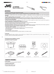
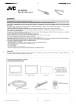
SYSTÈME DE TUNER DE TÉLÉVISION MOBILE KV-C10
1
2
R AUDIO L
HEADPHONE
For installation and connections, refer
to the separate manual.
Para la instalación y las conexiones,
refiérase al manual separado.
Pour l’installation et les raccordements,
se référer au manuel séparé.
2
TO DISPLAY
VOCAL
POWER
SUPPLY
OUTPUT
ANTENNA INPUT
1
VIDEO
ENGLISH
SISTEMA DE SINTONIZADOR DE TV MÓVIL
ESPAÑOL
KV-C10
FRANÇAIS
MOBILE TV TUNER SYSTEM
3
INPUT 1
INPUT 2
4
VIDEO
L AUDIO R
VIDEO
CONT
VIDEO
L AUDIO R
This system is designed to enjoy TV programs by connecting
JVC mobile color monitor system KV-M700 (sold separately).
All operations and functions of the system including KV-M700
connected are explained in this instructions.
Este sistema ha sido diseñado para que pueda ver programas
de televisión conectando el sistema de monitor en color móvil
KV-M700 de JVC (en venta por separado). En estas instrucciones
se describen todas las operaciones y funciones del sistema,
incluyendo el KV-M700 conectado.
Ce système est conçu pour vous permettre de regarder des
émissions de télévision en connectant le système de moniteur
couleur mobile KV-M700 de JVC (vendu séparément). Le
fonctionnement et les fonctions du système avec le KV-M700
connecté sont expliqués dans ce manuel d’instructions.
INSTRUCTIONS
MANUAL DE INSTRUCCIONES
MANUEL D’INSTRUCTIONS
For customer Use:
Enter below the Model No. and Serial No.
which are located on the top or bottom of
the cabinet. Retain this information for
future reference.
Model No.
Serial No.
3351396B01-0
[J]
COVER.KV-C10[J]
3
00.11.28, 4:29 PM
ENGLISH
Safety points (Be sure to follow these points)
CAUTIONS
CAUTION
RISK OF ELECTRIC SHOCK
DO NOT OPEN
CAUTION:
TO REDUCE THE RISK OF ELECTRIC SHOCK.
DO NOT REMOVE COVER (OR BACK).
NO USER-SERVICEABLE PARTS INSIDE.
REFER SERVICING TO QUALIFIED SERVICE PERSONNEL.
The lightning flash with arrowhead symbol, within an equilateral
triangle, is intended to alert the user to the presence of
uninsulated "dangerous voltage" within the product's enclosure
that may be of sufficient magnitude to constitute a risk of electric
shock to persons.
The exclamation point within an equilateral triangle is intended to
alert the user to the presence of important operating and
maintenance (servicing) instructions in the literature
accompanying the appliance.
WARNING:
TO PREVENT FIRE OR SHOCK
HAZARD, DO NOT EXPOSE THIS
UNIT TO RAIN OR MOISTURE.
CAUTION:
This TV tuner unit or system should be used with DC
12V only.
To prevent electric shocks and fire hazards, DO NOT use
any other power source.
WARNINGS
• DO NOT INSTALL THE TV TUNER SYSTEM IN A
LOCATION WHICH OBSTRUCTS DRIVING,
VISIBILITY OR WHICH IS PROHIBITED BY
APPLICABLE LAWS AND REGULATIONS.
• THERE MAY BE LEGAL REGULATIONS DEFINING
THE PERMISSIBLE INSTALLATION LOCATIONS FOR
THE MONITOR SYSTEM WHICH DIFFER BY
COUNTRY OR BY STATE, BE SURE TO INSTALL THE
MONITOR SYSTEM IN A CORRECT LOCATION
ACCORDING TO SUCH LAWS.
• DO NOT INSTALL THE TV TUNER SYSTEM IN A
LOCATION WHICH OBSTRUCTS THE OPERATION
OF AN AIR BAG.
• THE DRIVER MUST NOT OPERATE THE TV TUNER
SYSTEM WHILE DRIVING.
OPERATING THE TV TUNER SYSTEM WHILE
DRIVING MAY LEAD TO CARELESSNESS AND
CAUSE AN ACCIDENT.
• DO NOT USE THE TV TUNER SYSTEM WHEN THERE
IS A PROBLEM OR MALFUNCTION.
IF THE TV TUNER SYSTEM IS USED IN AN
ABNORMAL CONDITION SUCH AS WHEN THE TV
TUNER SYSTEM IS EMITTING SMOKE OR AN
UNUSUAL SMELL, IT MAY CAUSE A FIRE OR SOME
OTHER PROBLEM.
* IMMEDIATELY STOP USING THE TUNER SYSTEM AND
CONSULT THE SALES OUTLET WHERE YOU PURCHASED
THE TUNER SYSTEM.
• DO NOT DISASSEMBLE THE TV TUNER SYSTEM OR
MAKE ANY CHANGES.
IF THE TUNER SYSTEM IS DISASSEMBLED OR
MODIFIED, IT MAY CAUSE MALFUNCTIONS OR A
FIRE OR OTHER ACCIDENTS.
• DO NOT PUT YOUR EYES OR FACE NEAR THE
ANTENNA ELEMENT.
IF YOU PUT YOUR EYES OR FACE NEAR THE
ANTENNA ELEMENT, YOU COULD BE INJURED.
• WHEN LIGHTNING OCCURS, DO NOT TOUCH THE
ANTENNA WIRE OR THE TV TUNER SYSTEM.
TOUCHING THE ANTENNA WIRE OR THE TV TUNER
SYSTEM UNDER SUCH CONDITIONS MAY CAUSE
ELECTROCUTION.
• KEEP THE TV TUNER SYSTEM AT AN APPROPRIATE
SOUND LEVEL WHILE DRIVING.
DRIVING WITH THE SOUND AT A LEVEL WHICH
PREVENTS YOU FROM HEARING SOUNDS OUTSIDE
OF AND AROUND THE VEHICLE MAY CAUSE AN
ACCIDENT.
• ASK A TRAINED TECHNICIAN TO INSTALL THE TV
TUNER SYSTEM.
INSTALLATION AND WIRING REQUIRE TRAINING
AND EXPERIENCE.
* TO BE SAFE, ASK THE SALES OUTLET WHERE YOU
PURCHASED THE TV TUNER SYSTEM TO PERFORM THE
INSTALLATION.
• DO NOT LET THE TV TUNER SYSTEM FALL OR BE
STRONGLY IMPACTED.
BE SURE NOT TO LET THE TV TUNER SYSTEM FALL
OR BE STRONGLY IMPACTED SINCE THIS MAY
CAUSE A MALFUNCTION OR FIRE.
• DO NOT WATCH THE MONITOR WITH THE ENGINE
OFF.
WATCHING THE MONITOR WITH THE ENGINE OFF
WILL CONSUME BATTERY POWER AND MAY
PREVENT THE ENGINE FROM STARTING.
* STOP YOUR VEHICLE IN A SAFE LOCATION WHEN
OPERATING THE TV TUNER SYSTEM.
2
• THE DRIVER MUST NOT WATCH THE TELEVISION
OR VIDEOS WHILE DRIVING.
IF THE DRIVER WATCHES THE TELEVISION OR A
VIDEO WHILE DRIVING, IT MAY LEAD TO
CARELESSNESS AND CAUSE AN ACCIDENT.
EN02-08.KV-C10[J]f
2
00.11.28, 4:16 PM
• Do not leave the liquid crystal panel surface
facing upwards on top of the dashboard.
(storage temperature range: –20°C to +80°C
(–4°F to 176°F) )
ENGLISH
Cautions for the liquid crystal panel (sold separately)
• Do not strongly impact the liquid crystal panel.
+80°C
–20°C
–20°C to +80°C
During the summer,
temperatures can
reach as high as
100°C (212°F).
When the liquid crystal panel reaches high
temperatures or low temperatures, chemical
changes occur within the liquid crystal panel
which may cause malfunctions.
• There are red spots, blue spots and green
spots on the panel surface. This is a
characteristic of liquid crystal panels and is
not a problem.
Spots
The liquid crystal panel is built with very high
precision technology and has at least 99.99%
effective image pixels. Be aware that on
0.01% of the panel there may be missing
pixels or constantly light pixels.
• When the temperature is very cold or very
hot, the image may not appear clearly or may
move slowly.
In addition, movement of the image may seem
to be out of sync or the image quality may
decline in such environments. Note that this
is not a malfunction or problem.
(usage temperature range: 0°C to +40°C
(32°F to 104°F) )
0°C (32°F) or colder
40°C (104°F) or hotter
3
EN02-08.KV-C10[J]f
3
00.11.28, 4:16 PM
ENGLISH
Thank you for purchasing a JVC product. Please read all instructions carefully before operation, to
ensure your complete understanding and to obtain the best possible performance from the unit.
CONTENTS
CONTROLS AND FEATURES ......................................... 5
TV tuner unit .................................................................................. 5
Color monitor (KV-M700, sold separately) .................................. 6
Remote controller (supplied with KV-M700) ............................... 7
Installing the batteries ................................................................. 8
BASIC OPERATIONS .................................................... 9
Watching television ......................................................................... 9
Storing channels in memory (Auto memory) ............................. 11
Setting the channel selection ........................................................ 12
Watching playback of external component ................................ 13
OTHER FUNCTIONS .................................................. 15
Setting the RF input ..................................................................... 15
ADJUSTMENTS ......................................................... 16
Adjusting the color ....................................................................... 16
Adjusting the brightness .............................................................. 17
Adjusting the contrast .................................................................. 18
Adjusting the headphone volume ................................................ 19
MAINTENANCE ......................................................... 20
TROUBLESHOOTING ................................................. 21
SPECIFICATIONS ....................................................... 23
INFORMATION (For U.S.A. only)
This equipment has been tested and found to comply with the limits for a Class B digital device,
pursuant to Part 15 of the FCC Rules. These limits are designed to provide reasonable protection
against harmful interference in a residential installation. This equipment generates, uses, and can
radiate radio frequency energy and, if not installed and used in accordance with the instructions, may
cause harmful interference to radio communications. However, there is no guarantee that interference
will not occur in a particular installation. If this equipment does cause harmful interference to radio or
television reception, which can be determined by turning the equipment off and on, the user is
encouraged to try to correct the interference by one or more of the following measures:
– Reorient or relocate the receiving antenna.
– Increase the separation between the equipment and receiver.
– Connect the equipment into an outlet on a circuit different from that to which the receiver is connected.
– Consult the dealer or an experienced radio/TV technician for help.
4
BEFORE USE
* For safety....
• Do not raise the volume level too much, as this
will block outside sounds, making driving
dangerous.
• Stop the car before performing any complicated
operations.
EN02-08.KV-C10[J]f
4
* Temperature inside the car....
If you have parked the car for a long time in hot
or cold weather, wait until the temperature in the
car becomes normal before operating the unit.
00.11.28, 4:16 PM
CONTROLS AND FEATURES
ENGLISH
TV tuner unit
Front
ANTENNA INPUT
1
2
3
INPUT 2
4
VIDEO
1
INPUT 1
VIDEO
CONT VIDEO
L AUDIO R
L AUDIO R
3
2
4
Back
OUTPUT
R AUDIO L
VIDEO
8
2
POWER
SUPPLY
VOCAL
TO DISPLAY
7
HEADPHONE
6
1
5
9
See pages in the parentheses for details.
Front
Back
1 ANTENNA INPUT jacks (for connecting the
diversity antenna)
2 INPUT 2 jacks
• VIDEO
• AUDIO L
• AUDIO R
3 VIDEO CONT (Control) jack
4 INPUT 1 jacks
• VIDEO
• AUDIO L
• AUDIO R
5
6
7
8
POWER SUPPLY connector
This jack is not in use.
TO DISPLAY connector
OUTPUT jacks
• VIDEO
• AUDIO L
• AUDIO R
9 HEADPHONE 1 and 2 jacks (19)
5
EN02-08.KV-C10[J]f
5
00.11.28, 4:16 PM
ENGLISH
Color monitor (KV-M700, sold separately)
Front
Back
1
2
3
4
5
Top
DOWN
UP
AUTO/MANU
MODE
POWER
6 7 8 9 p
See pages in the parentheses for details.
Front
Top
1 STANDBY lamp
2 Remote sensor (8)
3 Screen (Liquid crystal panel)
6 DOWN button (10)
7 UP button (10)
8 AUTO/MANU (Auto/Manual) button
(11, 12)
9 MODE button (10, 11, 12, 13)
p POWER button (9)
Back
4 System connection cable
5 Monitor stand guide slot
• When you use the monitor stand to install
JVC mobile color monitor system KV-M700
in your car, attach the monitor stand here.
For installation, refer to the Installation/
Connection Manual supplied with KV-M700.
6
EN02-08.KV-C10[J]f
6
00.11.28, 4:16 PM
1
MONI
p
CH
2
3
4
5
6
ENGLISH
Remote controller (supplied with KV-M700)
H/P
VOL
MODE
H/P
VOL
q
w
e
r
CH
COLOR
BRIGHT
CONTRA
VCR section
u
VCR
i
VCR
;
a
VCR section
7
8
9
VOCAL
SKIP
A.MEMO
o
t
y
RF
CALL
RM-RK37
See pages in the parentheses for details.
1
(Power) button (9)
2 3 H/P VOL (Headphone volume up)
button (19)
3 2 H/P VOL (Headphone volume down)
button (19)
4 BRIGHT button (17)
5 COLOR button (16)
6 2 (Down) button (16, 17, 18)
7 This button does not function for this
system.
8 A.MEMO (Auto memory) button (11)
9 SKIP button (12)
p 5 CH (Channel up) button (10)
q MODE button (10, 11, 12, 13)
w ∞ CH (Channel down) button (10)
e CONTRA (Contrast) button (18)
r 3 (Up) button (16, 17, 18)
t RF (Radio frequency) button (15)
y CALL button (14)
VCR section
The buttons in this section are used for operating
JVC mobile video cassette player KV-V8 or JVC
mobile video cassette recorder KZ-V10. For the
operation, refer to the instructions of KV-V8 or
KZ-V10.
u
i
o
;
a
(Power) button
1 (Rewind) button
7 (Stop) button
¡ (Fast-forward) button
3 (Play) button
7
EN02-08.KV-C10[J]f
7
00.11.28, 4:16 PM
ENGLISH
Before using the remote controller:
• Aim the remote controller directly at
the remote sensor on the color
monitor. Make sure there is no
obstacle in between.
• Do not expose the remote sensor to
strong light (direct sunlight or artificial
lighting).
Remote sensor
Installing the batteries
When the controllable range or effectiveness of the remote controller decreases, replace the
batteries.
1. Remove the back cover.
While pushing on the back cover, slide it in the direction
of the arrow.
2. Install the batteries.
Place the two batteries R03(UM-4)/AAA(24F) supplied
into the remote controller as illustrated.
3. Close the back cover.
Slide the back cover in the direction of the arrow until a
click is heard.
8
EN02-08.KV-C10[J]f
8
00.11.28, 4:16 PM
BASIC OPERATIONS
ENGLISH
Preparation
Before operating the system, make sure that all external components are correctly
connected and installed. For connecting the external components, refer to the
instructions and the installations supplied with the external components.
Watching television
4
3 2
2
3
DOWN
UP
AUTO/MANU
MODE
MONI
CH
H/P
VOL
MODE
H/P
VOL
4
CH
POWER
COLOR
KV-M700 color monitor
BRIGHT
CONTRA
KV-M700 remote controller
1
If the system is connected to the parking brake
system:
ACC
ON
Engage the parking brake and turn on the
engine.
If the system is not connected to the parking
brake system:
ACC
ON
Turn on the engine.
Note:
For installation and connections, refer to the Installation/
Connection Manual supplied with KV-M700.
2
Monitor
Remote
Turn on the power.
Press the POWER button on the monitor or the
(power) button on the remote controller.
POWER
CONTINUED TO THE NEXT PAGE
9
EN09-15.KV-C10[J]f
9
00.11.28, 4:17 PM
ENGLISH
3
Monitor
Select TV as the input source.
Remote
Press the MODE button on the monitor or the remote
controller repeatedly to select TV.
CH
H/P
VOL
MODE
MODE
4
H/P
VOL
TV
CH
Monitor
Remote
VIDEO 1
VIDEO 2
Select the channel you want to watch.
Press the UP or DOWN button on the monitor or the 5 CH
or ∞ CH on the remote controller to change the channels.
CH
UP
or
H/P
VOL
MODE
08
H/P
VOL
CH
Selected channel number appears
on the screen for a while.
DOWN
If the channel selection is set to “AUTO” (See page 12.)
You can select only the channels preset by the auto
memory function. (See page 11.)
If the channel selection is set to “MANUAL” (See page
12.)
You can select all the channels. (Channel coverage: VHF
channels 2 to 12, UHF channels 13 to 69)
5
Adjust the volume level on the car receiver.
To turn off the power
Press the POWER button on the monitor or the
(power) button on the remote controller.
• Turning off the engine will also turn off the TV tuner system.
10
EN09-15.KV-C10[J]f
10
00.11.28, 4:17 PM
The auto memory function picks up the TV broadcast signals in the area where you are and
stores them automatically in memory.
ENGLISH
Storing channels in memory (Auto memory)
MONI
CH
2
1
1
MODE
H/P
VOL
H/P
VOL
CH
COLOR
DOWN
UP
AUTO/MANU
MODE
CONTRA
BRIGHT
VCR
POWER
KV-M700 color monitor
2
1
Monitor
KV-M700 remote
controller
CALL
Press the MODE button on the monitor or the remote
controller repeatedly to select TV.
CH
MODE
A.MEMO
RF
SKIP
Select TV as the input source.
Remote
H/P
VOL
VOCAL
H/P
VOL
TV
MODE
VIDEO 1
VIDEO 2
CH
2
Start scanning TV broadcast signals.
Monitor
Press and hold the AUTO/MANU button on the monitor or
press the A.MEMO button on the remote controller.
The auto memory function starts and TV broadcast signals
are picked up and stored in memory while scanning.
Remote
A.MEMO
AUTO/MANU
SCAN
22
AUTO MEMORY
When scanning is over, the screen shows the TV program of the smallest channel number in
memory.
Notes:
• TV stations with weak signals are not be picked up, therefore not being stored in memory.
• If you drive from one broadcasting area to another, the stored channels will not be tuned in. In this
case, perform the auto memory function again to store the stations in another area.
11
EN09-15.KV-C10[J]f
11
00.11.28, 4:17 PM
ENGLISH
Setting the channel selection
You can set the channel selection method either to select only the receivable channels in
memory or to select all the channels.
Remember that if you want to select only the receivable channels, you must store the channels
first. To store them, see page 11.
MONI
2
1
CH
1
H/P
VOL
MODE
H/P
VOL
CH
COLOR
DOWN
UP
AUTO/MANU
MODE
BRIGHT
POWER
CONTRA
VCR
KV-M700 color monitor
2
VOCAL
SKIP
A.MEMO
RF
CALL
KV-M700 remote controller
1
Monitor
Remote
Select TV as the input source.
CH
H/P
VOL
MODE
H/P
VOL
Press the MODE button on the monitor or the remote
controller repeatedly to select TV.
MODE
TV
CH
2
Monitor
VIDEO 1
VIDEO 2
Set the channel selection to “AUTO” or
“MANUAL.”
Remote
Press the AUTO/MANU button on the monitor or the SKIP
button on the remote controller.
Each time you press the button, the channel selection
alternates between “AUTO” and “MANUAL.”
SKIP
AUTO/MANU
AUTO:
Only the receivable channels stored in memory
can be selected. When you change the channel,
channel number and “AUTO” appear on the
screen for a while.
08
AUTO
MANUAL: All the channels can be selected. (Channel
coverage: VHF channels 2 to 12, UHF channels
13 to 69)
12
EN09-15.KV-C10[J]f
12
00.11.28, 4:17 PM
You can connect up to 2 external video components to the TV tuner unit.
To watch the playback, first follow steps 1 and 2 on page 9, then perform the following steps.
1
ENGLISH
Watching playback of external component
MONI
CH
H/P
VOL
DOWN
UP
AUTO/MANU
MODE
MODE
H/P
VOL
1
POWER
CH
KV-M700 color monitor
COLOR
BRIGHT
CONTRA
KV-M700 remote controller
1
Monitor
Select the input source.
Remote
Press the MODE button on the monitor or the remote
controller to select the input source you want.
Each time you press the button, the input source changes as
follows:
CH
H/P
VOL
MODE
MODE
H/P
VOL
CH
TV
VIDEO 1
VIDEO 2
The selected input source name also appears on the screen
for 3 seconds.
VIDEO1
EX: When VIDEO1 is selected.
2
Play back the external component.
To operate the external components, refer to the manuals of the connected
components.
3
Adjust the volume level on the car receiver.
13
EN09-15.KV-C10[J]f
13
00.11.28, 4:17 PM
ENGLISH
To check the current input source
Press the CALL button on the remote controller.
The current input source name appears on the screen for
3 seconds.
VOCAL
SKIP
A.MEMO
RF
CALL
CALL
RM-RK37
KV-M700 remote controller
To turn off the power
Press the POWER button on the monitor or the
(power) button on the remote controller.
• Turning off the engine will also turn off the TV tuner system.
Notes:
• When you watch the screen aslant, the picture might not be clear. This is not a malfunction. The
finest picture can be seen when you watch the screen straight.
• When JVC mobile video cassette player KV-V8 or JVC mobile video cassette recorder KZ-V10 is
connected to the system, you can also operate it by using the remote controller supplied with this
system. For the operation, refer to the instructions of KV-V8 or KZ-V10.
14
EN09-15.KV-C10[J]f
14
00.11.28, 4:17 PM
Setting the RF input
This system provides RF input selector. When you use JVC FM modulator KS-IF200, you can
listen to the sounds from the system through the receiver equipped with no line input. For
connecting and setting KS-IF200, refer to the instructions of KS-IF200.
VOCAL
SKIP
A.MEMO
RF
ENGLISH
OTHER FUNCTIONS
RF
CALL
RM-RK37
KV-M700 remote controller
RF
Press the RF button on the remote controller. Each time you press
the button, “RF ON” and “RF OFF” alternate, and the selected setting
appears on the screen.
RF ON: When reproducing the sound from the system through the
receiver equipped with no line input. (When using KSIF200)
RF OFF: Select this when you listen to the radio using the receiver
connected to this unit. (When using KS-IF200)
RF ON
RF OFF
15
EN09-15.KV-C10[J]f
15
00.11.28, 4:17 PM
ENGLISH
ADJUSTMENTS
Adjusting the color
You can adjust the color of the monitor system of KV-M700.
This function can be operated only by using the remote controller supplied with
KV-M700.
1
Press the COLOR button.
The color level appears on the screen.
MONI
CH
COLOR
H/P
VOL
MODE
H/P
VOL
08
COLOR
CH
COLOR
BRIGHT
CONTRA
COLOR
2
3
2
VCR
VOCAL
SKIP
Press the 3 (up) or 2 (down) button to adjust
the color.
RF
You can adjust the color level between 0 and 15.
A.MEMO
CALL
RM-RK37
Gets softer
Gets deeper
(0 +)
(= 15)
16
EN16-19.KV-C10[J]f
16
00.11.28, 4:17 PM
You can adjust the brightness of the monitor system of KV-M700.
This function can be operated only by using the remote controller supplied with
KV-M700.
1
ENGLISH
Adjusting the brightness
Press the BRIGHT button.
The brightness level appears on the screen.
MONI
CH
BRIGHT
H/P
VOL
MODE
H/P
VOL
08
BRIGHT
CH
COLOR
BRIGHT
CONTRA
VCR
VOCAL
SKIP
A.MEMO
BRIGHT
2
3
2
RF
Press the 3 (up) or 2 (down) button to adjust
the brightness.
You can adjust the brightness level between 0 and 15.
CALL
RM-RK37
Gets darker
Gets brighter
(0 +)
(= 15)
17
EN16-19.KV-C10[J]f
17
00.11.28, 4:17 PM
ENGLISH
Adjusting the contrast
You can adjust the contrast of the monitor system of KV-M700.
This function can be operated only by using the remote controller supplied with
KV-M700.
1
Press the CONTRA button.
The contrast level appears on the screen.
MONI
CH
H/P
VOL
MODE
CONTRA
H/P
VOL
08
CH
COLOR
BRIGHT
CONTRA
CONTRA
2
3
VCR
VOCAL
SKIP
A.MEMO
CONTRAST
2
RF
Press the 3 (up) or 2 (down) button to adjust
the contrast.
You can adjust the contrast level between 0 and 15.
CALL
RM-RK37
Gets lower
Gets higher
(0 +)
(= 15)
18
EN16-19.KV-C10[J]f
18
00.11.28, 4:17 PM
You can connect two pairs of headphones. When adjusting the headphone volume, the
adjustment applies to both connected headphones at the same time.
• You cannot adjust the headphone volume separately for the HEADPHONE 1 and 2 jacks.
This function can be operated only by using the remote controller supplied with
KV-M700.
ENGLISH
Adjusting the headphone volume
Press and hold the 3 (up) H/P VOL or 2
(down) H/P VOL button to adjust the
headphone volume.
MONI
CH
You can adjust the volume level between 0 and 35.
H/P
VOL
MODE
H/P
VOL
CH
COLOR
BRIGHT
CONTRA
Gets smaller (0 +)
2 and 3
H/P VOL
Gets louder (= 35)
CH
CH
VCR
H/P
VOL
VOCAL
SKIP
MODE
H/P
VOL
H/P
VOL
H/P
VOL
RF
CH
CH
A.MEMO
MODE
CALL
RM-RK37
The headphone volume level appears on the screen.
15
VOLUME
Note:
This adjustment is only for the connected headphones but not for the speakers in the car. When adjusting
the speaker volume, adjust it by using the car receiver.
19
EN16-19.KV-C10[J]f
19
00.11.28, 4:17 PM
MAINTENANCE
ENGLISH
To prevent damage to the system exterior
• Do not apply pesticides, benzine, thinner or other volatile substances to the unit.
The cabinet surface primarily consists of plastic materials.
• Do not wipe with benzine, thinner or similar substances because this will result in discoloration
or removal of the paint.
• When a cloth with a cleansing chemical is used, follow the caution points:
– Do not leave the unit in contact with rubber or vinyl products for long periods of time.
– Do not use cleansers which have polishing granules because this could damage the surface
of the unit.
Clean dirt by wiping lightly with a soft cloth
When the unit is very dirty, wipe with a well-wrung cloth dipped in a kitchen cleanser (neutral)
thinned by water and then go over the same surface with a dry cloth.
(Since there is the possibility of water drops getting inside of the unit, do not directly apply
cleanser to the surface.)
Caution:
If water drops or similar wet substances get inside of the monitor via the liquid crystal panel surface,
it may cause a malfunction.
20
EN20-23.KV-C10[J]f
20
00.11.28, 4:18 PM
What appears to be trouble is not always serious. Check the following points before calling a
service center.
Symptoms
Causes
Remedies
• Colored spots (red, blue and
green) appear on the screen.
This is a characteristic of liquid
crystal panels and is not a
malfunction.
See page 3.
• Sound can be heard but no
picture appears on the screen.
The parking brake has been
disengaged.
Engage the parking break.
The parking brake connection wire
(gray) is not connected correctly.
Check the connection and
correct it.
• No picture appears and sound
is not heard.
Correct input mode is not
selected.
Select the correct input mode.
• Remote controller does not
work.
The batteries have lost their
charge.
Install new batteries.
Remote sensor is exposed to
strong light.
Do not expose the remote
sensor to strong light.
You have driven to another
broadcasting area.
Perform the auto memory
function again.
• The preset channels cannot
be tuned in.
ENGLISH
TROUBLESHOOTING
21
EN20-23.KV-C10[J]f
21
00.11.28, 4:18 PM
ENGLISH
In the following environments, the image quality may be impaired.
Between buildings
A plane flies overhead
A train passes close by
Near electricity
transmission wires
Mountain shadow
Mountain or tree shadow
Distance from the broadcast
station
Movement
Interference
occurs
Doubling and tripling of
images (ghosts)
Interference
occurs
Image quality gradually
worsens and color instability
(displayed and then disappear)
Near an automobile, motor bike, high-voltage wires or a neon sign
Normal
sound
Spots appear on the screen
Near the transmission antenna of a radio station or an amateur
wireless station,or when a wireless device is being used in a
vehicle
Normal
sound
Color patterns appear on the
screen; colors are lost
22
EN20-23.KV-C10[J]f
22
00.11.28, 4:18 PM
TV TUNER UNIT
GENERAL
Input
Antenna:
Mini-jack × 4
Video: RCA pin × 2 circuits
1 V(p-p), 75 Ω
Audio: RCA pin × 2 circuits
0.5 V(rms)
Vocal: Mono mini-jack × 1
Video Control:
Mono mini-jack × 1
Output
Display:
8-pin DIN connector
Video: RCA pin × 1 circuit
1 V(p-p), 75 Ω
Audio: RCA pin × 1 circuit
0.5 V(rms)
Headphone:
Stereo mini-jack × 2
0 mW to 15 mW per channel
output into 32 Ω
Dimensions (W × H × D):
196 mm × 720 mm × 38 mm
(7-3/4" × 28-3/8" × 1-1/2")
Mass: 0.6 kg (1.4 lbs)
Channel coverage:
VHF: ch 2 – 12
UHF: ch 13 – 69
Power Requirement
Operating Voltage:
DC 14.4 V (11 V to 16 V allowance)
Grounding System:
Negative ground
Allowable Operating Temperature:
0°C to +40°C (32°F to 104°F)
Allowable Storage Temperature:
–20°C to +80°C (–4°F to 176°F)
ENGLISH
SPECIFICATIONS
Design and specifications subject to change
without notice.
DIVERSITY ANTENNA
Output impedance:
75 Ω × 4 (with mini plug)
Cable length: 4 m (13.3 ft)
Dimensions (approx.) (W × H × D):
460 mm × 460 mm × 18 mm
(18-1/8" × 18-1/8" × 3/4")
(without the cable)
Mass (each unit) (approx.):
165 g (0.37 lbs) (including the cable)
23
EN20-23.KV-C10[J]f
23
00.11.28, 4:18 PM
VICTOR COMPANY OF JAPAN, LIMITED
EN, SP, FR
V
J
COVER.KV-C10[J]
2
C
1100MNMMDWTAI
00.11.28, 4:29 PM