1
VIDEO CASSETTE RECORDER
HR-A592U
INSTRUCTIONS
Printed in Thailand
J4F90201A K
02/12
LPT0778-001A
COPYRIGHT © 2002 VICTOR COMPANY OF JAPAN, LTD.
Dear Customer,
Thank you for purchasing the JVC VHS video cassette recorder.
Before use, please read the safety information and precautions to
ensure safe use of your new VCR.
CAUTIONS
The lightning flash with arrowhead symbol, within
an equilateral triangle, is intended to alert the user
to the presence of uninsulated “dangerous voltage”
within the product’s enclosure that may be of
sufficient magnitude to constitute a risk of electric
shock to persons.
The exclamation point within an equilateral triangle
is intended to alert the user to the presence of
important operating and maintenance (servicing)
instructions in the literature accompanying the
appliance.
WARNING:
TO PREVENT FIRE OR SHOCK HAZARD, DO NOT EXPOSE
THIS UNIT TO RAIN OR MOISTURE.
CAUTION:
This video cassette recorder should be used with AC 120V~,
60Hz only.
To prevent electric shocks and fire hazards, DO NOT use any
other power source.
CAUTION:
Changes or modifications not approved by JVC could void user’s
authority to operate the equipment.
This equipment has been tested and found to comply with the limits
for a Class B digital device, pursuant to Part 15 of the FCC Rules.
These limits are designed to provide reasonable protection against
harmful interference in a residential installation. This equipment
generates, uses, and can radiate radio frequency energy and if not
installed and used in accordance with the instructions, may cause
harmful interference to radio communications. However, there is no
guarantee that interference will not occur in a particular installation. If
this equipment does cause harmful interference to radio or television
reception, which can be determined by turning the equipment off and
on, the user is encouraged to try to correct the interference by one or
more of the following measures:
Reorient or relocate the receiving antenna.
Increase the separation between the equipment and receiver.
Connect the equipment into an outlet on a circuit different from that
to which the receiver is connected.
Consult the dealer or an experienced radio/TV technician for help.
Failure to heed the following precautions may result in damage
to the VCR, Remote or video cassette.
1 DO NOT place the VCR . . .
...in an environment prone to extreme temperatures or humidity.
...in direct sunlight.
...in a dusty environment.
...in an environment where strong magnetic fields are generated.
...on a surface that is unstable or subject to vibration.
2. DO NOT block the VCR’s ventilation openings.
3. DO NOT place heavy objects on the VCR or on the Remote.
4. DO NOT place anything which might spill on the top of the VCR
or on the Remote.
5. AVOID violent shocks to the VCR during transport.
For Customer Use:
Enter below the Model No. and Serial No. which are located
on the rear of cabinet. Retain this information for future
reference.
Model No.
Serial No.
CAUTION:
TO PREVENT ELECTRIC SHOCK, MATCH WIDE BLADE OF PLUG
TO WIDE SLOT, FULLY INSERT.
ATTENTION:
POUR ÉVITER LES CHOCS ÉLECTRIQUES, INTRODUIRE LA
LAME LA PLUS LARGE DE LA FICHE DANS LA BORNE
CORRESPONDANTE DE LA PRISE ET POUSSER JUSQU’AU
FOND.
Note to CATV system installer:
This reminder is provided to call the CATV system installer’s
attention to Article 820-40 of the NEC that provides guidelines
for proper grounding and, in particular, specifies that the cable
ground shall be connected to the grounding system of the
building, as close to the point of cable entry as practical.
• Cassettes marked “VHS” (or “S-VHS”) can be used with this video
cassette recorder. However, S-VHS recording is not possible with
this model.
• This model is equipped with SQPB (S-VHS QUASI PLAYBACK)
that makes it possible to play back S-VHS recordings with regular
VHS resolution.
• HQ VHS is compatible with existing VHS equipment.
• As an Energy Star® Partner, JVC has determined that this product
or product model meets the Energy Star® guidelines for energy
efficiency.
*J4F90201A*
4F90201A/Cov-07
1
11/15/02, 03:55 PM
IMPORTANT PRODUCT SAFETY
INSTRUCTIONS
Electrical energy can perform many useful functions. But improper
use can result in potential electrical shock or fire hazards. This
product has been engineered and manufactured to assure your
personal safety. In order not to defeat the built-in safeguards,
observe the following basic rules for its installation, use and
servicing.
ATTENTION:
Follow and obey all warnings and instructions marked on your
product and its operating instructions. For your safety, please read
all the safety and operating instructions before you operate this
product and keep this booklet for future reference.
INSTALLATION
1. Grounding or Polarization
(A) Your product may be equipped with a polarized alternatingcurrent line plug (a plug having one blade wider than the other).
This plug will fit into the power outlet only one way. This is a
safety feature.
If you are unable to insert the plug fully into the outlet, try
reversing the plug. If the plug should still fail to fit, contact your
electrician to replace your obsolete outlet. Do not defeat the
safety purpose of the polarized plug.
(B) Your product may be equipped with a 3-wire grounding-type
plug, a plug having a third (grounding) pin. This plug will only fit
into a grounding-type power outlet. This is a safety feature.
If you are unable to insert the plug into the outlet, contact your
electrician to replace your obsolete outlet. Do not defeat the
safety purpose of the grounding-type plug.
2. Power Sources
Operate your product only from the type of power source indicated
on the marking label. If you are not sure of the type of power supply
to your home, consult your product dealer or local power company.
If your product is intended to operate from battery power, or other
sources, refer to the operating instructions.
3. Overloading
Do not overload wall outlets, extension cords, or integral
convenience receptacles as this can result in a risk of fire or electric
shock.
4. Power Cord Protection
Power supply cords should be routed so that they are not likely to
be walked on or pinched by items placed upon or against them,
paying particular attention to cords at plugs, convenience
receptacles, and the point where they exit from the product.
5. Ventilation
Slots and openings in the cabinet are provided for ventilation. To
ensure reliable operation of the product and to protect it from
overheating, these openings must not be blocked or covered.
• Do not block the openings by placing the product on a bed, sofa,
rug or other similar surface.
• Do not place the product in a built-in installation such as a
bookcase or rack unless proper ventilation is provided or the
manufacturer’s instructions have been adhered to.
6. Wall or Ceiling Mounting
The product should be mounted to a wall or ceiling only as
recommended by the manufacturer.
ANTENNA INSTALLATION INSTRUCTIONS
1. Outdoor Antenna Grounding
If an outside antenna or cable system is connected to the product,
be sure the antenna or cable system is grounded so as to provide
some protection against voltage surges and built-up static charges.
Article 810 of the National Electrical Code, ANSI/NFPA 70, provides
information with regard to proper grounding of the mast and
supporting structure, grounding of the lead-in wire to an antenna
discharge unit, size of grounding connectors, location of antenna
discharge unit, connection to grounding electrodes, and
requirements for the grounding electrode.
2. Lightning
For added protection for this product during a lightning storm, or
when it is left unattended and unused for long periods of time,
unplug it from the wall outlet and disconnect the antenna or cable
system. This will prevent damage to the product due to lightning and
power-line surges.
4F90201A/Cov-07
2
3. Power Lines
An outside antenna
system should not be
located in the vicinity of
overhead power lines
or other electric light or
power circuits, or where
it can fall into such
power lines or circuits.
When installing an
outside antenna system,
extreme care should be
taken to keep from
touching such power
lines or circuits as
contact with them might
be fatal.
USE
1. Accessories
To avoid personal injury:
• Do not place this product on an unstable cart, stand, tripod,
bracket, or table. It may fall, causing serious injury to a child or
adult, and serious damage to the product.
• Use only with a cart, stand, tripod, bracket, or table recommended
by the manufacturer or sold with the product.
• Use a mounting accessory recommended by the manufacturer
and follow the manufacturer’s instructions for any mounting of
the product.
• Do not try to roll a cart with small casters across thresholds or
deep-pile carpets.
2. Product and Cart Combination
A product and cart combination should be
moved with care. Quick stops, excessive
force, and uneven surfaces may cause the
product and cart combination to overturn.
3. Water and Moisture
Do not use this product near water—for
example, near a bath tub, wash bowl,
kitchen sink or laundry tub, in a wet
basement, or near a swimming pool and
the like.
4. Object and Liquid Entry
Never push objects of any kind into this product through openings
as they may touch dangerous voltage points or short-out parts that
could result in a fire or electric shock. Never spill liquid of any kind
on the product.
5. Attachments
Do not use attachments not recommended by the manufacturer of
this product as they may cause hazards.
6. Cleaning
Unplug this product from the wall outlet before cleaning. Do not use
liquid cleaners or aerosol cleaners. Use a damp cloth for cleaning.
7. Heat
The product should be situated away from heat sources such as
radiators, heat registers, stoves, or other products (including
amplifiers) that produce heat.
SERVICING
1. Servicing
If your product is not operating correctly or exhibits a marked
change in performance and you are unable to restore normal
operation by following the detailed procedure in its operating
instructions, do not attempt to service it yourself as opening or
removing covers may expose you to dangerous voltage or other
hazards. Refer all servicing to qualified service personnel.
2. Damage Requiring Service
Unplug this product from the wall outlet and refer servicing to
qualified service personnel under the following conditions:
a. When the power supply cord or plug is damaged.
b. If liquid has been spilled, or objects have fallen into the product.
c. If the product has been exposed to rain or water.
11/15/02, 03:55 PM
d.
e.
f.
If the product does not operate normally by following the
operating instructions. Adjust only those controls that are
covered by the operating instructions as an improper
adjustment of other controls may result in damage and will
often require extensive work by a qualified technician to restore
the product to its normal operation.
If the product has been dropped or damaged in any way.
When the product exhibits a distinct change in performance—
this indicates a need for service.
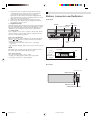
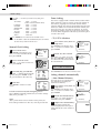
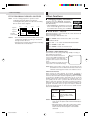
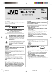
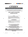
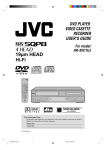
Buttons, Connectors and Indicators
Front Panel
REC
3. Replacement Parts
POWER
When replacement parts are required, be sure the service technician
has used replacement parts specified by the manufacturer or which
have the same characteristics as the original part. Unauthorized
substitutions may result in fire, electric shock or other hazards.
STOP/EJECT
Cassette loading slot
PLAY
4. Safety Check
PLAY
Upon completion of any service or repairs to this product, ask the
service technician to perform safety checks to determine that the
product is in safe operating condition.
POWER
STOP/EJECT
REW
FF
VIDEO (MONO) L Ð AUDIO Ð R
REC
How to use the Remote
Before use, insert two AAA size batteries into the Remote with the
polarity ( and ) matched correctly as indicated on the battery
compartment or on the lid.
• Point the Remote toward the remote sensor on the target
component.
• The maximum operating distance of the remote control is about 5
m.
NOTE:
VIDEO/AUDIO (L/R)
input connectors
FF
CH+/–
Remote
sensor
REW
Display Panel
If the Remote does not work properly, remove its batteries, wait for a
few seconds, replace the batteries and then try again.
Video heads cleaning
Use a dry cleaning cassette — TCL-2— when:
• Rough, poor picture appears while a tape is played back.
• The picture is unclear or no picture appears.
Timer
Record
Play/Still/
Recording
Pause
Recording
VCR
PM
Multi-Function Display
Rear Panel
AC power cord
UHF/VHF IN (ANT)
OUT
UHF/VHF
VIDEO
IN(ANT)
L
OUT(TV)
AUDIO
R
UHF/VHF OUT (TV)
VIDEO/AUDIO (L/R) OUT
4F90201A/Cov-07
3
11/15/02, 03:55 PM
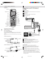
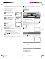
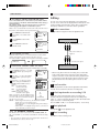
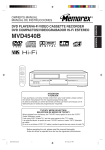
– Buttons, Connectors and Indicators –
Remote
Connections and VCR channel
Setting
POWER
POWER
Number keys
AUX
REC
1
2
3
4
5
6
7
8
9
–
0 (AUX)
CH–/+
2
+
CH
REC
1
PAUSE
PAUSE
Check contents
Make sure the package contains all of the accessories listed
in “Specifications”.
Situate VCR
Place the VCR on a stable, horizontal surface.
3
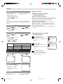
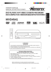
Connect VCR to TV
PLAY
REW
STOP
PLAY
REW
Antenna or cable
Coaxial cable
FF
FF
ENTER
MENU
MENU
ENTER
STOP
TIMER
CANCEL
C.RESET
SP/EP
– SET +
SET–/+
TV/VCR
TIMER
CANCEL
C.RESET
TV/VCR
A.MONITOR
SP/EP
DISPLAY
A.MONITOR
TV POWER
–
TV POWER
INPUT
–
TV CH
TV VOL
Flat feeder
Matching transformer
(not supplied)
OUT
UHF/VHF
DISPLAY
+
VIDEO
+
IN(ANT)
TV CH–/+
INPUT
L
OUT(TV)
TV VOL–/+
AUDIO
R
UHF/VHF
OUT
VIDEO
IN(ANT)
L
OUT(TV)
AUDIO
R
This Remote transmit A code
signals only; it is not applicable
to B code signals.
Back of VCR
On-screen display
If you press DISPLAY on the Remote, you can see the current VCR
status on the TV screen. Press DISPLAY again to exit on-screen
display.
The indications are not recorded even if the VCR is in the recording
mode.
WHILE WATCHING TV
DAY AND CLOCK TIME
8 : 30 AM THU
STEREO SAP
CH 125
CHANNEL
00 : 00 : 00 SP
TAPE
SPEED
REAL TIME COUNTER
STEREO
WHILE OPERATING A TAPE
OPERATING MODE
8 : 30 AM THU
HI-FI STEREO
HI-FI
AUTO REPEAT
AUTO TRACKING
OUTPUT
SELECTION
4F90201A/Cov-07
TAPE IN
AUTO TR.
STEREO
To 75 Ω terminal
RF cable (supplied)
Audio/video cable (not supplied)
To audio/video input connectors
STEREO AND
SEPARATE AUDIO
PROGRAM (SAP)
OUTPUT
SELECTION
TV
00 : 00 : 00 SP
4
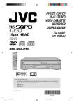
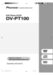
RF Connection
1 Disconnect the TV antenna from the TV.
2 Connect the TV antenna cable to the UHF/VHF IN
terminal on the rear of the VCR.
3 Connect the supplied RF cable between the UHF/VHF
OUT terminal on the rear of the VCR and the TV’s
antenna input terminal.
AV Connection
(improves picture quality during tape playback.)
If your TV is equipped with audio/video input connectors
1 Connect the antenna, VCR and TV as shown in the
illustration.
2 Connect an audio/video cable between the AUDIO/
VIDEO OUT connectors on the rear of the VCR and the
audio/video input connectors on the TV.
• Even if you are using audio/video cables to connect your
VCR to your TV, you must also connect it using the RF
cable. This will ensure that you can record one show while
watching another.
11/15/02, 03:56 PM
– Connections and VCR channel Setting –
4
– Initial Settings –
Auto Clock Setting
Set VCR channel
To view playback of a recorded tape, or to watch a program
selected by the VCR's channel selector, the TV must be set to
channel 3 or 4 (video channel) when a TV is connected with
the 75 ohm coaxial cable only.
1 Connect the Antenna or Cable system.
• If you use a cable box, turn it on.
2 Plug the AC Power cord to the AC outlet.
3 Make sure the VCR is turned off.
1 Press and hold 3 or 4 on the
• If you press POWER, the Auto Clock set is not effective.
Remote for 3 seconds in standby
mode. The video channel will
start to flash in the display.
4 Wait at least three minutes and press POWER.
5
2 Turn ON the TV and set to CH 3
CH 125
or 4 to correspond with the
channel selected in step 1.
6 If the clock is not set, check the Antenna condition. The
Auto Clock may not function properly if the reception
condition is not good.
3 Turn on the VCR and select any
channel to receive a TV station
in your area. The channel
number will appear on the screen and display for about
4 seconds.
Initial Settings
Language Setting
The default setting is “ENGLISH”.
1
Access Menu screen
Press MENU on the Remote. Press SET
–/+ to select “SYSTEM SETUP”, then
press ENTER.
2
Access Language screen
Press SET –/+ to select “LANGUAGE”,
then press ENTER.
3
MENU
TIMER REC SET
AUTO REPEAT ON
ON
SAP
CH SETUP
SYSTEM SETUP
OFF
OFF
〈+/-/ENTER/MENU〉
Auto Clock Adjustment
The Auto Clock Adjustment will be performed at 12:00 PM
everyday if you turn off the VCR.
• If you use a cable box and you want Auto Clock adjustment
to be performed, the cable box must be left on.
• The Auto Clock Adjustment is not effective when there is a
difference of more than 5 minutes exists between the builtin clock time and the actual time.
To Set Auto Clock To Off
When shipped from factory “AUTO CLOCK” option is set to ON.
But if you do not want Auto Clock set (Adjustment):
1 Turn on the VCR.
SYSTEM SETUP
CLOCK SET
LANGUAGE/IDIOMA/LANGUE
NO NOISE BACKGROUND
ON OFF
AUTO CLOCK ON OFF
STANDARD TIME
DAYLIGHT SAVING TIME
á+/-/ENTER/MENUñ
2 Press MENU.
3 Press SET –/+ to select “SYSTEM SETUP” option, then
press ENTER.
4 Press SET –/+ to select “AUTO CLOCK” option.
5
Select language
LANGUAGE/IDIOMA/LANGUE
This VCR offers you the language
ENGLISH
choice to view menus and some
messages — in English, Spanish or
FRANCAIS
French. Press SET –/+ to select your
〈+/-/ENTER/MENU〉
desired language, then press ENTER.
Press MENU twice to return to normal screen.
Clock Setting
Preparations
You must set the date and time for timer recording.
6
Press ENTER to select OFF.
Press MENU repeatedly to return to the normal screen.
• When “AUTO CLOCK” is set to OFF, the Auto Clock
adjustment does not function. Set the clock manually.
To Set Standard Time
In the rare event that you live within broadcast range of two
stations in two different time zones, the VCR may recognize
the wrong station for the Auto Clock set.
To correct the situation:
1 Press MENU.
Auto Clock Setting
2 Press SET –/+ to select “SYSTEM SETUP” option, then press
The Auto Clock function will automatically set the built-in
clock (Month, Day, Year and Time) when the VCR is
connected to an Antenna or Cable system and it is turned
off. As the VCR searches for a receivable station in your area
and it receives a broadcast signal for Auto Clock, the Auto
Clock needs several minutes to set itself.
4F90201A/Cov-07
Press DISPLAY to check the clock on the TV screen.
5
ENTER.
3 Press SET –/+ to select “STANDARD TIME” option, then
press ENTER.
11/15/02, 03:56 PM
– Initial Settings –
4 Press SET –/+ to select your time zone, then press
ENTER.
ATLANTIC
EASTERN
CENTRAL
MOUNTAIN
PACIFIC
ALASKA
HAWAII
AUTO
:
:
:
:
:
:
:
:
Tuner Setting
This VCR is equipped with a channel memory feature which
allows channels to skip up or down to the next channel set
into memory, skipping over unwanted channels. Before
selecting channels, they must be programmed into the VCR’s
memory. In addition to normal VHF and UHF channels, this
VCR can receive up to 113 Cable TV channels. To use this
VCR with an antenna, set the TV/CATV menu option to the
TV mode. When shipped from the factory, this menu option
is in the CATV mode.
GMT – 4 hours
(GMT: Greenwich Mean Time)
GMT – 5 hours
GMT – 6 hours
GMT – 7 hours
GMT – 8 hours
GMT – 9 hours
GMT – 10 hours
AUTO SET
5 Press MENU twice to return to the normal screen.
NOTE: To be able to select the standard time, the clock must
first be set by “AUTO CLOCK” once.
Access Menu screen
Press MENU on the Remote. Press
SET –/+ to select “SYSTEM SETUP”,
then press ENTER.
2
Access Clock Set screen
Press SET –/+ to select “CLOCK SET”,
then press ENTER.
3
Set month, day, year and time
Press SET –/+ until the desired month
appears, then press ENTER. Set the
day, year and time in the same way.
MENU
TIMER REC SET
AUTO REPEAT ON
ON
SAP
CH SETUP
SYSTEM SETUP
Start clock
〈+/-/ENTER/MENU〉
SYSTEM SETUP
CLOCK SET
LANGUAGE/IDIOMA/LANGUE
NO NOISE BACKGROUND
ON OFF
AUTO CLOCK ON OFF
STANDARD TIME
DAYLIGHT SAVING TIME
á+/-/ENTER/MENUñ
Press MENU to return to normal
screen.
3
DAY
1 (SAT)
YEAR
20 0 3
TIME
1 2 : 0 0 AM
DAY
YEAR
TIME
3
2 6 (WED)
20 0 3
8 : 3 0 AM
á+/-/ENTER/CANCEL/MENUñ
To make corrections any time during the process
Press CANCEL repeatedly until the item you want to change
blinks, then press SET –/+.
NOTE:
After a power failure or disconnection of the power, the
timer settings will be lost. In this case, reset the present time.
4F90201A/Cov-07
6
MENU
TIMER REC SET
AUTO REPEAT ON
ON
SAP
CH SETUP
SYSTEM SETUP
OFF
OFF
〈+/-/ENTER/MENU〉
2
Perform TV/CATV Selection
Press SET –/+ to select “TV/CATV”,
then press ENTER to select the TV
or CATV mode. The arrow indicates
the selected mode.
CH SETUP
TV
CATV
AUTO CH MEMORY
ADD/DELETE
〈+/-/ENTER/MENU〉
TV
- VHF/UHF channels
CATV - CABLE TV channels
Press MENU twice to return to normal screen.
MONTH
MONTH
Access Menu screen, then CH
Setup screen
OFF
OFF
á+/-/ENTER/CANCEL/MENUñ
4
1
Press MENU on the Remote. Press
SET –/+ to select “CH SETUP”, then
press ENTER.
Manual Clock Setting
1
– TV/CATV Selection
Setting channels automatically
– Auto Channel Memory
The VCR can receive a maximum of
181 channels by presetting the
channels into memory.
Access Menu screen, then CH
Setup screen
Press MENU on the Remote. Press
SET –/+ to select “CH SETUP”, then
press ENTER.
1
2
Perform Auto Channel Memory
Press SET –/+ to select “AUTO CH
MEMORY”, then press ENTER.
3 Complete Auto Channel Memory
The auto tuning will start. The
channel display will count up and
when finished, the screen returns to
normal.
11/15/02, 03:56 PM
MENU
TIMER REC SET
AUTO REPEAT ON
ON
SAP
CH SETUP
SYSTEM SETUP
OFF
OFF
〈+/-/ENTER/MENU〉
CH SETUP
TV
CATV
AUTO CH MEMORY
ADD/DELETE
〈+/-/ENTER/MENU〉
CH 001
– Initial Settings –
Setting channels manually
– Manual Channel Set
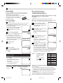
Playback
You can add the channels you want or delete the channels
you do not want manually.
1
Access Menu screen, then
CH Setup screen
Press MENU on the Remote.
Press SET –/+ to select “CH
SETUP”, then press ENTER.
2
MENU
TIMER REC SET
AUTO REPEAT ON
ON
SAP
CH SETUP
SYSTEM SETUP
OFF
OFF
PLAY
POWER
Access ADD/DELETE Mode
2
ADD
Press SET –/+ on the Remote to
select a channel number you
want to add or delete.
FF
CH SETUP
Make sure the window side is up, the rear
label side is facing you and the arrow on
the front of the cassette is pointing
towards the VCR.
〈+/-/ENTER/MENU〉
1
REW
REC
TV
CATV
AUTO CH MEMORY
ADD/DELETE
Add or Delete desired
channels
STOP/EJECT
VIDEO (MONO) L Ð AUDIO Ð R
〈+/-/ENTER/MENU〉
Press SET –/+ to select “ADD/
DELETE”, then press ENTER.
3
Basic Playback
1 Load a cassette
á
CH 012
• Do not apply too much pressure when
inserting.
• The VCR turns on, and the counter is
reset, automatically.
• If the cassette’s record safety tab has been removed, playback
begins automatically.
• If you press any operation buttons while the cassette is not
“ will flash on the screen for 4 seconds.
loaded, “
+/-/0-9/ENTER/MENUñ
To add channels
Press ENTER until “ADD” appears on the screen to set to
add the unmemorized channel.
2
Start playback
Press PLAY (
).
To delete channels
Press ENTER until “DELETE” appears on the screen to set
to delete the channel from memory.
3
Repeat 1 to 2 to add or delete other channel.
During playback
Press MENU three times to return to normal screen.
Stop playback
NOTE: You can’t select “CH SET UP” if you set the channel
to “L”.
Press STOP (
Remote.
) on the
OR Press STOP/EJECT (■/
) on the VCR.
Pause playback and view still picture
Press PAUSE.
• Press PLAY ( ) to resume
normal playback.
Pause and Frame-by-Frame playback
Press PAUSE to pause, then
press PAUSE repeatedly.
Press PLAY ( ) to resume
normal playback.
4F90201A/Cov-07
7
11/15/02, 03:56 PM
– Playback –
Playback Features
Slow-motion
Press PLAY ( ) on the
OR Press Play (
Remote.
VCR.
• Playback will proceed at
1/10 th of the normal speed.
• Press PLAY ( ) to resume
normal playback.
) on the
Automatic tracking adjustment
NOTE:
During slow motion picture, some noise might appear on
the TV screen. Use the SET–/+ on the Remote to eliminate
the noise.
Speed search
) or
OR Press REW (
Press REW (
) or FF
) on the VCR.
FF (
) on the Remote.
(
• Press PLAY ( ) to resume
normal playback.
Variable speed search
OR Press REW (
) or FF
Press REW (
) or FF
) repeatedly on
(
) repeatedly on the
(
the VCR.
Remote.
• Press PLAY ( ) to resume
normal playback.
• Each time you press REW
) or FF (
) the
(
playback speed changes.
TAPE SPEED
PICTURE SEARCH SPEED
PRESS ONCE
PRESS TWICE
SP
3X
5X
EP
9X
15X
When the tape is not running
Whenever you insert a tape and start playback, automatic
tracking starts working and continuously analyzes the signal
to enable optimum picture quality during playback.
Manual tracking adjustment
If automatic tracking cannot eliminate noises well during
playback, press SET –/+ on the Remote to eliminate the
noises. Press it briefly for a fine adjustment, or press and
hold for a coarse adjustment.
• Press SP/EP on the Remote again to reactivate automatic
tracking.
Playing back tape repeatedly
– Auto Repeat Play
1
) or FF
OR Press REW (
(
) on the VCR.
Access Menu screen
Press MENU on the Remote.
Press SET –/+ to select “AUTO
REPEAT”.
2
Select ON/OFF
Press ENTER to select “ON” or
“OFF”.
Press MENU to return to normal
screen.
Start Auto Repeat Play
Press PLAY. The tape will play
over and over until the repeat
mode is canceled.
Eject the tape
Press STOP/EJECT (■/ ) on
the VCR.
• You can also eject the
cassette when the VCR is
turned off.
Turn off the VCR
Press POWER on the
Remote.
4F90201A/P08-Back
OR Press POWER (
the VCR.
8
MENU
TIMER REC SET
AUTO REPEAT ON
ON
SAP
CH SETUP
SYSTEM SETUP
OFF
OFF
〈+/-/ENTER/MENU〉
3
Rewind/fast-forward
Press REW (
) or FF
(
) on the Remote.
Adjusting tracking condition
– Tracking Adjustment
/l) on
11/15/02, 03:56 PM
MENU
TIMER REC SET
AUTO REPEAT ON
ON
SAP
CH SETUP
SYSTEM SETUP
〈+/-/ENTER/MENU〉
OFF
OFF
Recording
Recording Features
It may be unlawful to record or play back copyrighted
material without the consent of the copyright owner.
Accidental erasure prevention
To prevent accidental recording on a recorded
cassette, remove its record safety tab.
To record on it later, cover the hole
with adhesive tape.
Specifying recording length
- Instant Timer Recording (ITR)
The Instant Timer Recording feature provides a simple
and convenient way to make a timed
recording.
Record safety tab
Basic Recording
1 Load a cassette
Make sure the record safety tab is intact. If not, cover the
hole with adhesive tape before inserting the cassette.
• The VCR turns on, and the counter
is reset, automatically.
• If you press any operation buttons
while the cassette is not loaded,
“ “ will flash on the screen for 4
seconds.
EXAMPLE: Instant Timer Recording for 30 minutes.
When a TV is connected with an audio/video cable, turn the
TV on and select the video input mode on the TV.
1
Load a cassette tape with the
erase prevention tab intact. The
clock display will change in the
counter display.
2
Press SP/EP to select the desired
tape speed SP or EP.
The counter and SP or EP will
appear on the screen for about 4
seconds.
2
Select recording channel
CH 001
Press CH–/+ or the Number keys on
the Remote [CH–/+ on the VCR].
• If you connect the TV and the VCR
only using the RF connection, press
TV/VCR on the Remote so that the
VCR mode indicator lights on the display panel, to view the
program to be recorded.
3
00 : 00 : 00 SP
3
Set tape speed
4
Press SP/EP.
00 : 00 : 00 SP
4 Start recording
On the VCR, press REC. Or on the
Remote, while holding REC, press
PLAY ( ).
During recording
Pause recording
Press PAUSE.
• Press PAUSE on the Remote or
REC on the VCR to resume
recording.
• You can select channel in the
recording pause mode.
Stop recording
Press STOP (
Remote.
4F90201A/P08-Back
) on the
CH 001
Press the Number keys or CH –/+
to select the channel to be
recorded.
The channel number will appear
on the screen and display for
about 4 seconds.
CH 125
ITR 0 : 30
Press REC on the VCR or while
CH 125
holding REC, press PLAY ( ) on
the Remote to begin recording.
Press REC on the VCR again to
stop recording after 30 minutes.
Each additional press of REC will
increase recording time as shown in the chart below, up
to a maximum of 6 hours. The ITR and recording time
will appear on screen for about 4 seconds.
NOTES: • Press REC to increase
the time needed for
recording (See the
chart).
• To cancel ITR, press
STOP ( ) or turn off
the power.
Press
Recording time
once
NORMAL REC
twice
0:30
3 times
1:00
4 times
1:30
5 times
2:00
6 times
3:00
7 times
4:00
8 times
5:00
9 times
6:00
10 times NORMAL REC
Watching one program while recording another
OR Press STOP/EJECT
(■/ ) on the VCR.
9
During recording…
• If you connect the TV and the VCR only using the RF
connection to view pictures from the VCR, press TV/VCR
on the Remote so that VCR mode indicator goes off from
the display panel. (The TV broadcast being recorded
disappears.)
• If you are using the AV connection to view pictures from
the VCR, change the TV’s input mode from AV to TV.
Then, select the channel you want to watch, on the TV.
11/15/02, 03:56 PM
Timer Recording
TO CORRECT THE SETTINGS
Timer recording can be programmed on-screen with
the remote control. The built-in timer allows automatic
unattended recording of up to 8 programs within 1
month.
When setting the Timer Recording, press ENTER until the
desired setting blinks, then re-enter the setting using SET –/+.
When finished, press ENTER.
NOTES:
• After timer recording is completed, the VCR turns off
automatically.
• You can program the timer recording while a regular
recording is in progress; the menu screens will not be
recorded.
• The timer recording will start at 5 seconds before the time
you predetermined.
EXAMPLE: Program a timer recording for the 26th day,
channel 125 (CATV), 11:00 - 11:30 PM on timer program
number 1 (Tape speed: EP).
TO SET DAILY/WEEKLY TIMER
When a TV is connected with an audio/video cable, turn the
TV and this VCR on and select the video input mode on the
TV.
1
2
Press MENU on the Remote.
Check the “TIMER REC SET”
option is selected, then press
ENTER.
Press SET –/+ to select one of
the program lines, then press
ENTER.
3
Press SET –/+ to select the
date, then press ENTER.
4
Set the start time, end time,
channel and tape speed as in
step 3.
NOTE: To record from external
source, press SET –/+
and set the channel to
"L". "L" will appear next
to CH 125 (or 69).
5
6
To enter other programs,
repeat step 2 through 4. Or,
press MENU twice to return
to the normal screen.
Press TIMER on the Remote.
The power will go off, the
TIMER REC indicator ( ) will
light and the VCR stands by
for recording.
MENU
TIMER REC SET
AUTO REPEAT ON
ON
SAP
CH SETUP
SYSTEM SETUP
OFF
OFF
START
-:--:--:--:--:--:--:--:--
END
-:--:--:--:--:--:--:--:--
START
-:--:--:--:--:--:--:--:--
END
-:--:--:--:--:--:--:--:--
CH
-----------------
-
CH
-----------------
START END CH
11:00PM 11:30PM 125
-:-- -:-- ---:-- -:-- ---:-- -:-- ---:-- -:-- ---:-- -:-- ---:-- -:-- ---:-- -:-- ---
START END CH
11:00PM 11:30PM 125
-:-- -:-- ---:-- -:-- ---:-- -:-- ---:-- -:-- ---:-- -:-- ---:-- -:-- ---:-- -:-- ---
MO-SA (Monday to Saturday)
MO-FR (Monday to Friday)
WKL-TH (Weekly Thursday)
TO CONFIRM THE SETTINGS
Press SET –/+ to select the
“TIMER REC SET” option in the
MENU. Then press ENTER to
display the timer program list.
Press MENU twice to return to
the normal screen.
EP
-
TO CANCEL A PROGRAM
〈+/-/ENTER/CANCEL/MENU〉
DATE
26(SU)
------------------------------------
WKL-WE
(Weekly Wednesday)
SU-SA (Sunday to Saturday)
-
〈+/-/ENTER/CANCEL/MENU〉
DATE
26(SU)
------------------------------------
Example
One month later
minus one day
〈+/-/ENTER/CANCEL/MENU〉
DATE
26(SU)
------------------------------------
When setting the date in step 3 in the Setting the Timer
Recording section, press SET – repeatedly.
The setting changes as follows:
The current day (Friday)
〈+/-/ENTER/MENU〉
DATE
-----------------------------------------
NOTES: • The VCR cannot be used while the TIMER REC
indicator ( ) is lit.
• After a power failure or disconnection of the
power plug, all programmed recording settings
must be reset upon resumption of power. In this
case, reset the clock and reprogram any timer
recordings.
• Press CANCEL to move cursor backward for
correction.
EP
-
Press the SET –/+ to select the
“TIMER REC SET” option in the
MENU. Then press SET –/+ to
select the unnecessary program,
and press CANCEL to cancel the
program.
〈+/-/ENTER/CANCEL/MENU〉
To use the VCR while it is in timer recording standby mode
Press TIMER. After you use the VCR, press TIMER again
to put the VCR into timer recording standby mode.
4F90201A/P08-Back
10
11/15/02, 03:56 PM
DATE
26(SU)
------------------------------------
START END CH
11:00PM 11:30PM 125
-:-- -:-- ---:-- -:-- ---:-- -:-- ---:-- -:-- ---:-- -:-- ---:-- -:-- ---:-- -:-- ---
EP
-
〈+/-/ENTER/CANCEL/MENU〉
DATE
-----------------------------------------
START
-:--:--:--:--:--:--:--:--
END
-:--:--:--:--:--:--:--:--
CH
-----------------
〈+/-/ENTER/CANCEL/MENU〉
-
– Timer Recordings –
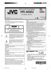
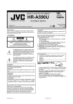
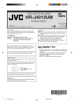
IF THE PROGRAM OVERLAPS ANOTHER
NOTE: Do not overlap programs as portions of the
conflicting programs will be lost. The first
recording time has priority over the next recording
time as shown in the diagram.
8 : 00
9 : 00
10 : 00
11 : 00
Program 1
Other Functions
Changing display information
Each time you press DISPLAY, the display
panel shows the time counter and the clock
time alternatively.
• When DISPLAY on the Remote is pressed,
time counter will appear on the TV screen.
To reset the time counter, press C. RESET on the Remote.
Program 2
BLUE BACK — ON/OFF
Deleted Parts
Program 3
Non Recorded Portion Parts
Recording
Control Settings
Prog.1
Prog.2
Prog.3
NOTES: • The everyday/every week recording can be made
continuously until the recording is canceled or
the tape reaches the end.
• During timer recording, the automatic rewinding
mechanism does not function.
When this function is set to “ON”, the TV screen becomes all
blue in the following case:
When receiving a channel not in use.
1
Press MENU on the remote. Press SET –/+ to select
“SYSTEM SETUP”.
2
3
4
Press SET –/+ to select “NO NOISE BACKGROUND”.
Press ENTER to select “ON”.
Press MENU to return to normal screen.
STEREO RECORDING AND PLAYBACK
RECORDING STEREO BROADCASTS
The VHS Hi-Fi audio system permits high fidelity recording of
MTS STEREO TV broadcasts.
When a MTS STEREO broadcast is
STEREO
received, the STEREO will appear on the
screen for about 4 seconds and the
program can be viewed or recorded in
stereo.
The Hi-Fi STEREO recording procedure
is the same as for normal recordings.
NOTE: When using a CATV system, stereo TV programs may be
transmitted over a mono cable channel. In this case the word
"STEREO" will not appear and the sound will be in mono.
OUTPUT SELECTION
When viewing an MTS STEREO TV program, or playing a
prerecorded VHS Hi-Fi STEREO videotape, press A.MONITOR to
select how the audio will be heard through the speakers. Normally
set to the Hi-Fi STEREO position, this button can be set to the
MONO position if the stereo broadcast or videotape audio is of
poor quality. The "R" and "L" positions allow the audio from the
Right or Left Hi-Fi channel to be heard over both TV speakers.
This button has no effect when viewing a MONO videotape or TV
program. Each time when you press the button, OUTPUT
SELECTION display appears on the screen for several seconds.
Refer to the chart below.
OUTPUT
SELECTION
SOUND HEARD ON BOTH
SPEAKERS
STEREO
L ch
R ch
MONO
STEREO
LEFT CHANNEL AUDIO
RIGHT CHANNEL AUDIO
MONO
NOTES: • When playing back a tape that is not recorded in
Hi-Fi stereo mode, the audio will automatically be
monaural.
• When listening to a VHS Hi-Fi video tape or MTS
broadcast through the VHF/UHF jack (Audio/
Video cord not connected), the sound will be
monaural.
4F90201A/P08-Back
11
11/15/02, 03:56 PM
– Other Functions –
Editing
SEPARATE AUDIO PROGRAM (SAP)
Your VCR is fitted with an SAP broadcast system which enables
you to switch to a SEPARATE AUDIO PROGRAM when viewing a
selected channel.
This function applies only when the program is broadcast in
multi-languages through the SAP broadcast system.
When a TV is connected with an audio/video cable, turn the TV and
this VCR on, and select the video input mode the TV.
1
Press MENU on the Remote.
Press SET –/+ to select “SAP”
option.
2
Press ENTER to select “ON”
position.
3
Press MENU to return to
normal screen.
MENU
TIMER REC SET
AUTO REPEAT ON
ON
SAP
CH SETUP
SYSTEM SETUP
You can use your VCR as the playback or recording VCR.
You can use a camcorder as the playback VCR and your VCR
as the recording VCR. Refer also to the other components’
instruction manuals for connection and its operations.
1 Make connections
Example: When using this VCR as the playback VCR
OFF
OFF
This VCR (for playback)
〈+/-/ENTER/MENU〉
MENU
TIMER REC SET
AUTO REPEAT ON
ON
SAP
CH SETUP
SYSTEM SETUP
To audio/video out
OFF
OFF
〈+/-/ENTER/MENU〉
Audio/video cable (not
supplied)
LISTENING TO SAP
When the VCR is turned on or a channel selection is made, make
certain "SAP" appears on the screen for about 4 seconds.
This means that the "Separate Audio Program" broadcasting is available.
STEREO SAP
To audio/video input
SAP
OR
DAYLIGHT SAVING TIME SETTING
Another VCR (for recording)
You can set the Daylight saving time automatically or manually.
1
Press MENU. Press SET –/+ to select
“SYSTEM SETUP” option, then press
ENTER.
2 Press SET –/+ to select “DAYLIGHT
SAVING TIME” option, then press
ENTER.
3 Press SET –/+ to select one of the
options, then press ENTER. Press
MENU until the MENU screen is
cleared.
ON:
for manual setting
(forward one hour)
OFF: for manual setting
(back one hour)
AUTO: for automatic setting
(read XDS in the signal)
When you want to set the Daylight Saving
Time manually, on the first Sunday in April
you set to “ON”, and on the last Sunday in
October you set to “OFF”.
MENU
TIMER REC SET
AUTO REPEAT ON
ON
SAP
CH SETUP
SYSTEM SETUP
OFF
OFF
〈+/-/ENTER/MENU〉
SYSTEM SETUP
CLOCK SET
LANGUAGE/IDIOMA/LANGUE
NO NOISE BACKGROUND
ON OFF
AUTO CLOCK ON OFF
STANDARD TIME
DAYLIGHT SAVING TIME
á+/-/ENTER/MENUñ
• When using this VCR as the recording VCR, connect this
VCR’s audio/video input connectors to the audio/video
output connectors on the other VCR. If the playback VCR
is monaural, connect the audio output connector on the
playback VCR to the left audio input connector on this
VCR.
2 Load cassettes
Insert the playback cassette into the playback VCR and the
cassette to be recorded on into the recording VCR.
DAYLIGHT SAVING TIME
ON
OFF
AUTO
〈+/-/ENTER/MENU〉
NOTES: • When shipped from factory, the DAYLIGHT SAVING
TIME option is set to AUTO position.
• When the clock is not set, Daylight Saving Time setting is
not available.
• When there is no Daylight Saving Time in your area, always select OFF position in step 3.
3 Select input mode on recording VCR
Select the correct external input on the recording VCR.
On this VCR (when using this VCR as the recording VCR);
Select “L” — when connecting the other VCR to the audio/video
input connectors on the front panel.
Press O (AUX) or CH–/+ on the Remote [CH–/+ on the VCR].
4 Start playback
Press PLAY (
JVC TV Remote Control
This Remote can control some functions (TV POWER, INPUT, TV
CH –/+ and TV VOL –/+) of a remote controllable JVC TV without setting.
NOTE:
) on the playback VCR.
5 Start recording
Press REC on the recording VCR.
• It’s not possible to operate a unit not equipped with a remote sensor.
• This Remote can control a JVC TV only.
4F90201A/P08-Back
12
11/15/02, 03:56 PM
Before Requesting Service
Make sure by first checking the following points.
SYMPTOM
CAUSE
POSSIBLE SOLUTION
POWER
No power.
The AC power cord is not connected.
Connect the AC power cord to the AC
outlet.
Although the power is on, it
does not operate.
Cassette is not inserted.
Insert a video cassette.
Antenna connection is not correct.
Connect it correctly.
Antenna cable is disconnected.
Reconnect the antenna cable.
The video channel is not in the correct
position.
Set it to CH 3 or 4.
The TV is not set to the video channel
3 or 4.
Set the TV channel selector to the 3 or 4
position.
The TV/VCR selector is set at TV mode
(The VCR indicator is not lit).
INPUT is set to the LINE mode.
The TV/CATV menu option setting.
Press the TV/VCR selector button (The VCR
indicator will light).
The erase prevention tab of the video
cassette is broken off.
Place a piece of vinyl tape over the gap.
INPUT is set to the LINE mode.
Press the Number key or CH –/+ button to
select your desired TV program.
The time is not set correctly.
Reset the present time.
The recording start/end time is not set
correctly.
Set the start/end time.
The TIMER button has not been
pressed (The TIMER REC symbol
not lit on the display).
Press the TIMER button (The TIMER REC
symbol is lit on the display).
TV BROADCAST RECEPTION
A TV program that is selected by
the VCR does not appear on the
screen.
Press the Number key or CH –/+ button to
select your desired TV program.
RECORDING
TV recording does not work.
Timer recording does not work.
is
PLAYBACK
No picture on screen when
playing back a recorded tape.
The TV is not set to the video channel 3
or 4.
Noise bars on screen.
Tracking adjustment beyond range of
automatic tracking circuit.
Video heads are dirty.
The tape is worn or damaged.
Set to the video channel 3 or 4 or
adjust the fine tuning button on your
TV set.
Adjust tracking manually using the SET – or
+ buttons on the remote control.
Have the video heads cleaned.
Try another tape.
It is not aimed at the remote sensor.
Aim it at the remote sensor.
Distance too far or too much light in
the room.
Operate within 15 feet (5 meters)
reduce the light in the room.
There is an obstacle in the path of the
beam.
Clear the path of the beam.
The batteries are weak.
Replace the batteries.
The +, – polarity of the batteries are
not inserted correctly.
Insert correctly.
The TV/VCR function is in the VCR
mode.
Set to TV, or turn off the VCR power
button.
REMOTE CONTROL
Remote control does not work.
TV programs cannot be seen
using the TV selector.
4F90201A/P08-Back
13
11/15/02, 03:56 PM
Specifications
GENERAL
Power requirement
Power consumption
Power on
Power off
Temperature
Operating
Storage
Operating position
Dimensions (W x H x D)
Weight
Format
Maximum recording time
SP
EP
:
AC 120 V, 60 Hz
:
:
9W
1.7 W
:
:
:
:
:
:
5°C to 40°C (41°F to 104°F)
–20°C to 60°C (–4°F to140°F)
Horizontal only
360 mm x 95 mm x 222.5 mm (14-3/16" x 3-3/4" x 8-3/4")
3.2 kg (7.1 lbs)
VHS NTSC standard
:
:
210 min. with ST-210 video cassette
630 min. with ST-210 video cassette
:
NTSC-type color signal and EIA monochrome signal, 525 lines/60 fields
:
:
:
DA-4 (Double Azimuth) head helical scan system
42 dB
230 lines
:
:
:
100 Hz to 10,000 Hz
20 Hz to 20,000 Hz
RCA connectors (IN x 1, OUT x 1)
:
Frequency-synthesized tuner
:
:
:
:
Channels 2–13
Channels 14–69
113 Channels
Channel 3 or 4 (switchable; preset to Channel 3 when shipped) 75 ohms,
unbalanced
VIDEO/AUDIO
Signal system
Recording/Playback
system
Signal-to-noise ratio
Horizontal resolution
Frequency range
Normal audio
Hi-Fi audio
Input/Output
TUNER
Tuning system
Channel coverage
VHF
UHF
CATV
RF output
TIMER
:
Clock reference
:
Program capacity
Memory backup for timer :
Quartz
1-month programmable timer/8 programs
Approx. 5 sec.
ACCESSORIES
:
Provided accessories
RF cable (F-type), Infrared remote control unit, “AAA” battery x 2
Specifications shown are for SP mode unless specified otherwise.
E. & O.E. Design and specifications subject to change without notice.
4F90201A/P08-Back
14
11/15/02, 03:56 PM
LIMITED WARRANTY
VCR EXCHANGE -90
JVC COMPANY OF AMERICA warrants this Video Cassette Recorder and all parts thereof, except as set forth below ONLY TO THE
ORIGINAL PURCHASER AT RETAIL to be FREE FROM DEFECTIVE MATERIALS AND WORKMANSHIP from the date of the original
retail purchase for the period shown below. ("The Warranty Period")
THIS LIMITED WARRANTY IS VALID ONLY IN THE FIFTY (50) UNITED STATES, THE DISTRICT OF COLUMBIA AND IN THE
COMMONWEALTH OF PUERTO RICO.
WHAT WE WILL DO:
If this product is found to be defective within the warranty period, JVC will, at its option, either repair or replace the defective
part(s) or replace the product with a new or refurbished functionally equivalent product. Within 90 days from date of retail sale,
repair or replacement will be at no charge.
WHAT YOU MUST DO FOR WARRANTY SERVICE:
Please do not return your product to the retailer. Instead, please box the product carefully, preferably in the original carton,
and ship, insured to the JVC repair/replacement facility nearest you.
To obtain the address of the location nearest you, please call (800) 537-5722 or visit our website http://www.jvc.com.
A COPY OF YOUR BILL OF SALE, A COMPLETED WARRANTY REPAIR/REPLACEMENT FORM AND ALL OF THE ORIGINAL
ACCESSORIES WHICH CAME WITH YOUR UNIT MUST ACCOMPANY THE PRODUCT TO BE ELIGIBLE FOR REPAIR/
REPLACEMENT UNDER WARRANTY.
If you have any questions concerning your JVC Product, please contact our Customer Relations Department at (800) 252-5722.
WHAT IS EXCLUDED:
The warranty does not cover:
1. Products which have been subject to abuse, accident, alteration, modification, tampering, negligence, misuse, faulty installation,
lack of reasonable care, or if repaired or serviced by anyone other than a service facility authorized by JVC to render such
service, or if affixed to any attachment not provided with the products, or if the model or serial number has been altered,
tampered with, defaced or removed.
2. Initial installation, installation and removal, from "built in" entertainment centers, and other mounting systems.
3. Operational adjustments covered in the Owner's Manual, normal maintenance, including head cleaning.
4. Damage that occurs in shipment, due to act of God, and cosmetic damage.
5. Signal reception problems and failures due to line power surge.
6. Products used for commercial purposes (including but not limited to rental).
7. Accessories.
8. Batteries (except that Rechargeable Batteries are covered for 90 days from the date of purchase).
There are no express warranties except as listed above.
AFTER THE WARRANTY:
Please contact JVC's Customer Relations Department at (800) 252-5722 to obtain the cost of out of warranty repair or replacement.
THE DURATION OF ANY IMPLIED WARRANTIES, INCLUDING THE IMPLIED WARRANTY OF MERCHANTABILITY, IS LIMITED
TO THE DURATION OF THE EXPRESS WARRANTY HEREIN.
JVC SHALL NOT BE LIABLE FOR ANY LOSS OF USE OF THE PRODUCT, INCONVENIENCE, OR ANY OTHER DAMAGES,
WHETHER DIRECT, INCIDENTAL OR CONSEQUENTAL (INCLUDING, WITHOUT LIMITATION, DAMAGE TO TAPES, RECORDS OR
DISCS) RESULTING FROM THE USE OF THIS PRODUCT, OR ARISING OUT OF ANY BREACH OF THIS WARRANTY. ALL EXPRESS
AND IMPLIED WARRANTIES, INCLUDING THE WARRANTIES OF MERCHANTABILITY AND FITNESS FOR PARTICULAR
PURPOSE, ARE LIMITED TO THE WARRANTY PERIOD SET FORTH ABOVE.
Some states do not allow the exclusion of incidental or consequential damages or limitations on how long an implied warranty
lasts, so these limitations or exclusions may not apply to you. This warranty gives you specific legal rights and you may also have
other rights which vary from state to state.
1700 Valley Road
Wayne, New Jersey 07470
JVC COMPANY OF AMERICA
DIVISION OF JVC AMERICAS CORP.
http://www.jvc.com
○ ○ ○ ○ ○ ○ ○ ○ ○ ○ ○ ○ ○ ○ ○ ○ ○ ○ ○ ○ ○ ○ ○ ○ ○ ○ ○ ○ ○ ○ ○ ○ ○ ○ ○ ○ ○ ○ ○ ○ ○ ○ ○ ○ ○ ○ ○ ○ ○ ○ ○ ○ ○ ○ ○ ○ ○ ○ ○ ○ ○ ○ ○ ○ ○ ○ ○ ○
REFURBISHED PRODUCTS CARRY A SEPARATE WARRANTY. THIS WARRANTY DOES NOT APPLY. FOR DETAIL OF
REFURBISHED PRODUCT WARRANTY, PLEASE REFER TO THE REFURBISHED PRODUCT WARRANTY INFORMATION
PACKAGED WITH EACH REFURBISHED PRODUCT.
For customer use:
Enter below the Model No. and Serial No. which is located either on the rear, bottom or side of the cabinet.
Retain this information for future reference.
Model No.: _____________________________
Purchase Date: __________________________
4F90201A/P08-Back
15
Serial No.: _________________________________
Name Of Dealer: ___________________________
11/15/02, 03:56 PM
FOR SERVICING (Only in U.S.A.)
WARRANTY REPAIR / REPLACEMENT FORM
PLEASE COMPLETE THE FOLLOWING:
PLEASE NOTE: P.O. BOXES ARE NOT ACCEPTABLE
NAME: __________________________________________________________________
STREET ADDRESS: ________________________________________________________
CITY: ________________________ STATE ___________________ ZIPCODE __________________
DAY TIME PHONE NUMBER: ________________________________________
_________________________________________________________________________________________________________________
REASON FOR RETURN
________________________________________________________
________________________________________________________
________________________________________________________
Please do not return your product to the retailer. Instead, please box the product carefully, preferably in the original carton,
and ship, insured to the JVC repair/replacement facility nearest you.
A COPY OF YOUR BILL OF SALE, A COMPLETED WARRANTY REPAIR/REPLACEMENT FORM AND ALL OF THE ORIGINAL
ACCESSORIES WHICH CAME WITH YOUR UNIT MUST ACCOMPANY THE PRODUCT TO BE ELIGIBLE FOR REPAIR/REPLACEMENT
UNDER WARRANTY.
To obtain the address of the location nearest you, please call (800) 537-5722 or visit our website http://www.jvc.com.
If you have any questions concerning your JVC Product, please contact our Customer Relations Department at (800) 252-5722.
HOW TO LOCATE YOUR JVC SERVICE CENTER
TOLL FREE: 1-800-537-5722
http://www.jvc.com
Dear Customer,
In order to receive the most satisfaction from your purchase, please read the instruction booklet before operating the unit. In
the event that repair is necessary, or for the address nearest your location within the Continental United States, please call 1800-537-5722 for your nearest authorized servicer or visit our website at www.JVC.com. Remember to retain your Bill of Sale
for Warranty Service.
— JVC
JVC SERVICE & ENGINEERING
COMPANY OF AMERICA
DIVISION OF JVC AMERICAS CORP.
Sophisticated electronic products may require occasional service. Just as quality is a keyword in the engineering and
production of the wide array of JVC products, service is the key to maintaining the high level performance for which JVC is
world famous. The JVC service and engineering organization stands behind our products.
NATIONAL HEADQUARTERS
JVC SERVICE & ENGINEERING COMPANY OF AMERICA
DIVISION OF JVC AMERICAS CORP.
10 New Maple Avenue
Pine Brook, NJ 07058-9641
ACCESSORIES
To purchase accessories for your JVC product, you may
contact your local JVC Dealer.
From the 48 Continental United States call toll free:
1-800-882-2345 or on the web at www.JVC.com
4F90201A/P08-Back
16
Don’t service the product yourself.
CAUTION
To prevent electrical shock, do not open the cabinet. There
are no user serviceable parts inside.
Please refer to qualified service personnel for repairs.
11/15/02, 03:56 PM