1
ENGLISH
FRANÇAIS
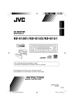
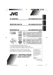
CD RECEIVER
RECEPTEUR CD
KD-S1501/KD-G152/KD-G151
For canceling the display demonstration, see page 7.
Pour annuler la démonstration des affichages, référez-vous à la page 7.
For installation and connections, refer to the separate manual.
Pour l’installation et les raccordements, se référer au manuel séparé.
INSTRUCTIONS
MANUEL D’INSTRUCTIONS
GET0287-003A
[EX/EU]
Cover_KD-S1501[EX_EU]f.indd 2
10/27/04 3:21:20 PM
ENGLISH
Thank you for purchasing a JVC product.
Please read all instructions carefully before operation, to ensure your complete understanding and to
obtain the best possible performance from the unit.
IMPORTANT FOR LASER PRODUCTS
1. CLASS 1 LASER PRODUCT
2. CAUTION: Do not open the top cover. There are no user serviceable parts inside the unit; leave
all servicing to qualified service personnel.
3. CAUTION: Visible and invisible laser radiation when open and interlock failed or defeated.
Avoid direct exposure to beam.
4. REPRODUCTION OF LABEL: CAUTION LABEL, PLACED OUTSIDE THE UNIT.
Warning:
If you need to operate the receiver while
driving, be sure to look ahead carefully or
you may be involved in a traffic accident.
How to forcibly eject a disc
If a disc cannot be recognized by the
receiver or cannot be ejected, ejects the disc
as follows.
How to reset your unit
• This will reset the microcomputer. Your
preset adjustments will also be erased.
• If a disc is loaded, it will eject. Be careful
not to drop the disc.
• If this does not work, try to reset your
receiver.
• Be careful not to drop the disc when it
ejects.
Note: Only for [EX] model users in UK and European countries
For security reasons, a numbered ID card is provided with this receiver, and the same ID number is
imprinted on the receiver’s chassis. Keep the card in a safe place, as it will help the authorities to
identify your receiver if stolen.
2
EN02-05_KD-S1501[EX_EU]f.indd 2
10/27/04 3:22:05 PM
How to reset your unit ...........................
How to forcibly eject a disc ...................
How to read this manual ........................
How to use the MODE button ...............
2
2
4
4
Control panel —
KD-S1501/
KD-G152/KD-G151 ...................
5
Parts identification .................................
5
Getting started ....................... 6
Basic operations .................................. 6
Canceling the display demonstrations ...
Setting the clock ....................................
7
7
Radio operations ................... 8
Listening to the radio........................... 8
Storing stations in memory ....................
Listening to a preset station ...................
9
9
FM RDS operations ................. 10
Searching for your favorite FM RDS
programme ....................................... 10
Disc operations ...................... 13
Playing a disc ..................................... 13
Selecting the playback modes................ 14
Sound adjustments ................ 15
Selecting preset sound modes
(C-EQ: custom equalizer) .................. 15
ENGLISH
Contents
Adjusting the sound ............................... 16
General settings — PSM ......... 17
Basic procedure ..................................... 17
Detaching the control
panel .................................. 19
Maintenance .......................... 20
More about this receiver ........ 21
Troubleshooting ..................... 22
Specifications ......................... 23
Storing your favorite programmes ......... 11
Using the standby receptions ................. 11
Tracking the same programme
—Network-Tracking Reception ........ 12
*For safety....
*Temperature inside the car....
• Do not raise the volume level too much, as
this will block outside sounds, making driving
dangerous.
• Stop the car before performing any
complicated operations.
If you have parked the car for a long time in
hot or cold weather, wait until the temperature
in the car becomes normal before operating the
unit.
3
EN02-05_KD-S1501[EX_EU]f.indd 3
10/27/04 3:22:06 PM
ENGLISH
How to read this manual
The following methods are used to made the
explanations simple and easy-to-understand:
• Some related tips and notes are explained in
“More about this receiver” (see page 21).
• Button operations are mainly explained with
the illustrations as follows:
How to use the MODE button
If you press MODE, the receiver goes into
functions mode, then the number buttons work
as different function buttons.
Ex.: When number button 2 works as
MO (monaural) button.
Press briefly.
Press repeatedly.
Press either one.
Time countdown indicator
Press and hold until
your desired response
begins.
To use these buttons for original functions
again after pressing MODE, wait for
5 seconds without pressing any of these buttons
until the functions mode is cleared.
• Pressing MODE again also clears the
functions mode.
Press and hold both
buttons at the same
time.
4
EN02-05_KD-S1501[EX_EU]f.indd 4
10/27/04 3:22:06 PM
KD-S1501/KD-G152/KD-G151
ENGLISH
Control panel —
Parts identification
Display window
1
2
3
4
5
6
7
8
9
p
q
w
e
r
t
y
u
i
o
+/– buttons
DISP (display) button
Loading slot
Display window
MODE button
0 (eject) button
¢/4
buttons
(standby/on/attenuator) button
SEL (select) button
EQ (equalizer) button
MO (monaural) button
SSM (Strong-station Sequential Memory)
button
CD button
FM/AM button
RPT (repeat) button
RND (random) button
T/P (traffic programme/programme type)
button
(control panel release) button
Number buttons
Display window
; Tuner reception indicators
MO (monaural), ST (stereo)
a RDS indicators
TP, PTY, AF, REG
s CD indicator
d RND
(disc random) indicator
f RPT (repeat) indicator
g LOUD (loudness) indicator
h EQ (equalizer) indicator
j Sound mode (C-EQ: custom equalizer)
indicators
ROCK, CLASSIC, POPS, HIP HOP, JAZZ,
USER
•
also works as the time countdown
indicator.
k Main display
l Source display
Volume level indicator
5
EN02-05_KD-S1501[EX_EU]f.indd 5
10/27/04 3:22:07 PM
ENGLISH
Getting started
Basic operations
To drop the volume in a moment (ATT)
~
To restore the sound, press it
again.
Ÿ
To turn off the power
You cannot select “CD” as the playback
source if there is no disc in the loading
slot.
Caution on volume setting:
Discs produce very little noise compared
with other sources. Lower the volume
before playing a disc to avoid damaging
the speakers by the sudden increase of the
output level.
!
Volume level appears.
Volume level indicator
⁄
Adjust the sound as you want.
(See pages 15 and 16.)
6
EN06-11_KD-S1501[EX_EU]f.indd 6
10/27/04 3:22:49 PM
ENGLISH
Canceling the display
demonstrations
Setting the clock
1
If no operations are done for about 20 seconds,
display demonstration starts.
[Initial: DEMO ON]—see page 17.
1
2
3
4 Finish the procedure.
2 Set the hour, minute, and clock
system.
1 Select “CLOCK H” (hour), then
adjust the hour.
2 Select “CLOCK M” (minute),
then adjust the minute.
3 Select “24H/12H,” then select
“24H” (hour) or “12H” (hour).
3 Finish the procedure.
To check the current clock time when the
power is turned off
To activate the display demonstration
In step 3 above...
7
EN06-11_KD-S1501[EX_EU]f.indd 7
10/27/04 3:22:50 PM
ENGLISH
Radio operations
Listening to the radio
~
2 Select the desired station frequencies.
Lights up when receiving an FM stereo
broadcast with sufficient signal strength.
When an FM stereo broadcast is hard to
receive
Selected band appears.
Ÿ
1
Start searching for a station.
2
When a station is received, searching
stops.
To stop searching, press the same
button again.
To tune in to a station manually
In step Ÿ above...
1
Lights up when monaural mode is activated.
Reception improves, but stereo effect will
be lost.
To restore the stereo effect, repeat the same
procedure. “MONO OFF” appears and the MO
indicator goes off.
8
EN06-11_KD-S1501[EX_EU]f.indd 8
10/27/04 3:22:51 PM
2
ENGLISH
Storing stations in memory
You can preset six stations for each band.
FM station automatic presetting—
SSM (Strong-station Sequential
Memory)
1 Select the FM band (FM1 – FM3)
you want to store into.
3
2
Preset number flashes for a while.
3
Listening to a preset station
1
2 Select the preset station (1 – 6) you
“SSM” flashes, then disappears when
automatic presetting is over.
want.
Local FM stations with the strongest signals are
searched and stored automatically in the FM
band.
Manual presetting
Ex.: Storing FM station of 92.5 MHz into the
preset number 4 of the FM1 band.
To check the current clock time while
listening to an FM (non-RDS) or AM station
• For FM RDS stations, see page 12.
1
9
EN06-11_KD-S1501[EX_EU]f.indd 9
10/27/04 3:22:51 PM
ENGLISH
FM RDS operations
Searching for your favorite FM RDS programme
You can tune in to a station broadcasting your
favorite programme by searching for a PTY code.
!
Start searching for your favorite
programme.
~
The last selected PTY code appears.
Ÿ
Select one of your favorite
programme type.
If there is a station broadcasting a
programme of the same PTY code as
you have selected, that station is tuned
in.
PTY codes
or
Select one of the twenty-nine PTY
codes.
NEWS, AFFAIRS, INFO, SPORT,
EDUCATE, DRAMA, CULTURE,
SCIENCE, VARIED, POP M (music),
ROCK M (music), EASY M (music),
LIGHT M (music), CLASSICS, OTHER
M (music), WEATHER, FINANCE,
CHILDREN, SOCIAL, RELIGION,
PHONE IN, TRAVEL, LEISURE, JAZZ,
COUNTRY, NATION M (music), OLDIES,
FOLK M (music), DOCUMENT
Ex.: When “ROCK M” is selected
10
EN06-11_KD-S1501[EX_EU]f.indd 10
10/29/04 11:49:32 AM
RDS (Radio Data System) allows FM
stations to send an additional signal along
with their regular programme signals.
By receiving the RDS data, this receiver can
do the following:
• Programme Type (PTY) Search (see page 10)
• Standby Reception of Traffic
Announcement —TA (see the following) or
your favorite programme (PTY) (see pages
12 and 18)
• Tracing the same programme automatically
—Network-Tracking Reception (see page 12)
• Programme Search (see page 18)
Storing your favorite programmes
You can store six favorite programme types.
3 Repeat steps 1 and 2 to store
other PTY codes into other preset
numbers.
4 Finish the procedure.
Using the standby receptions
TA Standby Reception
TA Standby Reception allows the receiver to
switch temporarily to Traffic Announcement
(TA) from any source other than AM.
The volume changes to the preset TA volume
level (see page 18).
Preset programme types in the number buttons
(1 – 6):
To activate TA Standby Reception
1 Perform steps ~ and Ÿ on page 10 to
• If the TP indicator lights up, TA Standby
Reception is activated.
• If the TP indicator flashes, TA Standby
Reception is not yet activated. (This occurs
when you are listening to an FM station
without the RDS signals required for TA
Standby Reception.)
To activate TA Standby Reception, tune in to
another station providing these signals. The
TP indicator will stop flashing and remain lit.
select a PTY code.
2 Select the preset number (1 – 6) you
want to store into.
ENGLISH
What you can do with RDS
The TP indicator either
lights up or flashes.
To deactivate the TA Standby Reception
The TP indicator goes off.
Ex.: When “ROCK M” is selected
11
EN06-11_KD-S1501[EX_EU]f.indd 11
10/27/04 3:22:52 PM
ENGLISH
PTY Standby Reception
PTY Standby Reception allows the receiver
to switch temporarily to your favorite PTY
programme from any source other than AM.
To activate and select your favorite PTY
code for PTY Standby Reception, see page
18.
The PTY indicator either lights up or flashes.
• If the PTY indicator lights up, PTY Standby
Reception is activated.
• If the PTY indicator flashes, PTY Standby
Reception is not yet activated.
To activate PTY Standby Reception, tune in
to another station providing these signals. The
PTY indicator will stop flashing and remain
lit.
Tracking the same programme—
Network-Tracking Reception
When driving in an area where FM reception
is not sufficient enough, this receiver
automatically tunes in to another FM RDS
station of the same network, possibly
broadcasting the same programme with stronger
signals (see the illustration below).
When shipped from the factory, NetworkTracking Reception is activated.
To change the Network-Tracking Reception
setting, see page 18.
Programme A broadcasting on different
frequency areas (01 – 05)
To deactivate the PTY Standby Reception,
select “OFF” for the PTY code (see page 18).
The PTY indicator goes off.
To check the current clock time while
listening to an FM RDS station
12
EN12-17_KD-S1501[EX_EU]f.indd 12
10/29/04 11:50:02 AM
ENGLISH
Disc operations
Playing a disc
All tracks will be played repeatedly until you
change the source or eject the disc.
To fast-forward or reverse the track
Fast-forwards.
Reverses.
To go to the next or previous tracks
Total playing time of Total track number
the inserted disc
of the inserted disc
To the following
tracks.
To the beginning of the current track, then
the previous tracks.
Elapsed playing
time
Current track
number
To go to a particular track directly
To select a number from 01 – 06:
To stop play and eject the disc
To select a number from 07 – 12:
13
EN12-17_KD-S1501[EX_EU]f.indd 13
10/27/04 3:23:20 PM
ENGLISH
Prohibiting disc ejection
You can lock a disc in the loading slot.
To check the current clock time while
listening to a disc
To cancel the prohibition, repeat the same
procedure.
Selecting the playback modes
You can use only one of the following playback modes at a time.
1
2 Select your desired playback mode.
Repeat play
Mode
Plays repeatedly
TRK RPT:
RPT OFF:
The current track.
• RPT lights up.
Cancels.
Mode
Plays at random
DISC RND:
All tracks of the current disc.
• RND
lights up.
Cancels.
Ex.: When “TRK RPT” is selected
Random play
RND OFF:
Ex.: When “DISC RND” is selected
14
EN12-17_KD-S1501[EX_EU]f.indd 14
10/27/04 3:23:20 PM
ENGLISH
Sound adjustments
Selecting preset sound modes (C-EQ: custom equalizer)
You can select a preset sound mode suitable to
the music genre.
~
Ÿ
Indication
For:
Preset values
BAS*1 TRE*2 LOUD*3
USER
(Flat sound)
00
00
OFF
ROCK
Rock or
disco music
+03
+01
ON
CLASSIC
Classical
music
+01
–02
OFF
POPS
Light music
+04
+01
OFF
HIP HOP
Funk or rap
music
+02
00
ON
JAZZ
Jazz music
+02
+03
OFF
*1 BAS: Bass
*2 TRE: Treble
*3 LOUD: Loudness
Ex.: When “ROCK” is selected
Indication pattern for each sound mode:
15
EN12-17_KD-S1501[EX_EU]f.indd 15
10/27/04 3:23:21 PM
ENGLISH
Adjusting the sound
You can adjust the sound characteristics to your
preference.
1
Ex.: When “TRE” is selected
Indication
To do:
Range
BAS*1
(bass)
Adjust the bass.
–06 (min.)
to
+06 (max.)
TRE*1
(treble)
Adjust the treble.
–06 (min.)
to
+06 (max.)
FAD*2
(fader)
Adjust the front
and rear speaker
balance.
R06 (Rear
only)
to
F06 (Front
only)
BAL
(balance)
Adjust the left
and right speaker
balance.
L06 (Left
only)
to
R06 (Right
only)
LOUD*1
(loudness)
Boost low and
high frequencies
to produce a wellbalanced sound at
low volume level.
LOUD ON
J
LOUD OFF
VOL*3
(volume)
Adjust the volume. 00 (min.) to
30 or 50
(max.)*4
2
Indication pattern changes as
you adjust the level.
*1 When you adjust the bass, treble, or
loudness, the adjustment you have made is
stored for the currently selected sound mode
(C-EQ) including “USER.”
*2 If you are using a two-speaker system, set
the fader level to “00.”
*3 Normally the +/– buttons work as the volume
control. So you do not have to select “VOL”
to adjust the volume level.
*4 Depending on the amplifier gain control
setting. (See page 18 for details.)
16
EN12-17_KD-S1501[EX_EU]f.indd 16
10/27/04 3:23:21 PM
General settings — PSM
ENGLISH
3 Adjust the PSM item selected.
Basic procedure
You can change PSM (Preferred Setting Mode)
items listed on the table that follows.
1
4 Repeat steps 2 and 3 to adjust the
other PSM items if necessary.
5 Finish the procedure.
2 Select a PSM item.
Ex.: When you select “AMP GAIN”
Indications
Selectable settings, [reference page]
DEMO
Display demonstration
DEMO ON:
CLOCK H
Hour adjustment
0 – 23 (1 – 12), [7]
[Initial: 0 (0:00)]
CLOCK M
Minute adjustment
00 – 59, [7]
[Initial: 00 (0:00)]
24H/12H
24 hours or 12 hours time
display
12H O 24H, [7]
[Initial: 24H]
CLK ADJ
Automatic clock setting
AUTO:
[Initial]; Display demonstration will be activated
automatically if no operation is done for about
20 seconds, [7].
DEMO OFF: Cancels.
OFF:
[Initial]; The built-in clock is automatically adjusted
using the CT (clock time) data in the RDS signal.
Cancels.
To be continued....
17
EN12-17_KD-S1501[EX_EU]f.indd 17
10/27/04 3:23:22 PM
ENGLISH
Indications
Selectable settings, [reference page]
AF-REG
Alternative frequency/
regionalization reception
When the received signals from the current station become weak....
AF:
[Initial]; Switches to another station (the programme
may differ from the one currently received), [12].
• The AF indicator lights up.
AF REG: Switches to another station broadcasting the same
programme.
• The AF and REG indicators light up.
OFF:
Cancels.
PTY-STBY
PTY standby
Activates PTY Standby Reception with one of the 29 PTY codes,
[12].
OFF [Initial] = PTY codes, [10] = (back to the beginning)
TA VOL
Traffic announcement
volume
[Initial: VOL 20]; VOL 00 – VOL 30 or 50*1, [11]
P-SEARCH
Programme search
ON:
OFF:
Using the AF data, the receiver tunes in to another
frequency broadcasting the same programme as the
original preset RDS station is if the preset station
signals are not sufficient.
[Initial]; Cancels.
ILL SW*2
Illumination switch
You can select the button illumination according to your
preference.
RED O GREEN
[Initial: RED]
TEL*2
Telephone muting
MUTING 1/MUTING 2: Select either one which mutes the
sounds while using the cellular phone.
OFF:
[Initial]; Cancels.
AMP GAIN
Amplifier gain control
You can change the maximum volume level of this receiver.
LOW PWR: VOL 00 – VOL 30 (Select this if the maximum
power of the speaker is less than 45 W to prevent
them from damaging the speaker.)
HIGH PWR: [Initial]; VOL 00 – VOL 50
*1 Depends on the amplifier gain control.
*2 Only for KD-S1501.
18
EN18-23_KD-S1501[EX_EU]f.indd 18
10/29/04 3:49:57 PM
When detaching or attaching the control panel,
be careful not to damage the connectors on
the back of the control panel and on the panel
holder.
Attaching the control panel
ENGLISH
Detaching the control panel
Detaching the control panel
Before detaching the control panel, be sure to
turn off the power.
19
EN18-23_KD-S1501[EX_EU]f.indd 19
10/27/04 3:23:52 PM
ENGLISH
Maintenance
How to clean the connectors
Frequent detachment will deteriorate the
connectors.
To minimize this possibility, periodically wipe
the connectors with a cotton swab or cloth
moistened with alcohol, being careful not to
damage the connectors.
To keep discs clean
A dirty disc may not play correctly.
If a disc does become dirty, wipe
it with a soft cloth in a straight line
from center to edge.
• Do not use any solvent (for
example, conventional record cleaner, spray,
thinner, benzine, etc.) to clean discs.
To play new discs
New discs may have some rough
spots around the inner and outer
edges. If such a disc is used, this
receiver may reject the disc.
To remove these rough spots, rub the edges
with a pencil or ball-point pen, etc.
Connector
Moisture condensation
Moisture may condense on the lens inside the
CD player in the following cases:
• After starting the heater in the car.
• If it becomes very humid inside the car.
Should this occur, the CD player may
malfunction. In this case, eject the disc and
leave the receiver turned on for a few hours
until the moisture evaporates.
How to handle discs
When removing a disc from Center holder
its case, press down the center
holder of the case and lift the
disc out, holding it by the
edges.
• Always hold the disc by the edges. Do not
touch its recording surface.
When storing a disc into its case, gently insert
the disc around the center holder (with the
printed surface facing up).
• Make sure to store discs into the cases after
use.
Do not use the following discs:
Warped
disc
Sticker
Sticker
residue
Disc
Stick-on
label
20
EN18-23_KD-S1501[EX_EU]f.indd 20
10/27/04 3:23:52 PM
Basic operations
Playing a CD-R or CD-RW
Turning off the power
• Use only “finalized” CD-Rs or CD-RWs.
• This receiver can play back multi-session
discs; however, unclosed sessions will be
skipped while playing.
• Some CD-Rs or CD-RWs may not play
back on this receiver because of their disc
characteristics, and for the following causes:
– Discs are dirty or scratched.
– Moisture condensation occurs on the lens
inside the receiver.
– The pickup lens inside the receiver is dirty.
– CD-R or CD-RW on which the files are
written with “Packet Write” method.
– There are improper recording conditions
(missing data, etc.) or media conditions
(stain, scratch, warp, etc.).
• CD-RWs may require a longer readout time
since the reflectance of CD-RWs is lower
than that of regular CDs.
• Do not use the following CD-Rs or CD-RWs:
– Discs with stickers, labels, or protective seal
stuck to the surface.
– Discs on which labels can be directly
printed by an ink jet printer.
Using these discs under high temperatures or
high humidities may cause malfunctions or
damages to discs.
• If you turn off the power while listening to a
disc, disc play will start from where playback
has been stopped previously, next time you
turn on the power.
Tuner operations
Storing stations in memory
• During SSM search...
– All previously stored stations are erased and
stations are stored newly.
– Received stations are preset in No. 1 (lowest
frequency) to No. 6 (highest frequency).
– When SSM is over, the station stored in
No. 1 will be automatically tuned in.
• When storing a station manually, a previously
preset station is erased when a new station is
stored in the same preset number.
FM RDS operations
• Network-Tracking Reception requires two
types of RDS signals—PI (Programme
Identification) and AF (Alternative
Frequency) to work correctly. Without
receiving these data correctly, NetworkTracking Reception will not operate.
• If a Traffic Announcement is received, the
volume level (TA Volume) automatically
changes to the preset level.
Disc operations
General
• This receiver has been designed to reproduce
CDs, and CD-Rs (Recordable)/CD-RWs
(Rewritable) in audio CD (CD-DA) format.
• When a disc has been loaded, selecting “CD”
for the playback source starts disc play.
Inserting a disc
• When a disc is inserted upside down, the disc
automatically ejects.
• Do not insert 8 cm discs (single CD) and
unusual shape discs (heart, flower, etc.) into
the loading slot.
ENGLISH
More about this receiver
Changing the source
• If you change the source, playback also stops
(without ejecting the disc).
Next time you select “CD” for the playback
source, disc play starts from where it has been
stopped previously.
Ejecting a disc
• If the ejected disc is not removed within
15 seconds, the disc is automatically inserted
again into the loading slot to prevent it from
dust. (Disc will not play this time.)
General settings—PSM
• If you change the “AMP GAIN” setting from
“HIGH PWR” to “LOW PWR” while the
volume level is set higher than “VOL 30,” the
receiver automatically changes the volume
level to “VOL 30.”
21
EN18-23_KD-S1501[EX_EU]f.indd 21
10/27/04 3:23:53 PM
ENGLISH
Troubleshooting
What appears to be trouble is not always serious. Check the following points before calling a service
center.
Symptoms
FM/AM
Disc playback
Remedies
The volume level is set to
the minimum level.
Adjust it to the optimum
level.
Connections are incorrect.
Check the cords and
connections.
• This receiver does not
work at all.
The built-in microcomputer
may have functioned
incorrectly due to noise, etc.
Reset the receiver (see page
2).
• SSM automatic presetting
does not work.
Signals are too weak.
Store stations manually.
• Static noise while listening
to the radio.
The aerial is not connected
firmly.
Connect the aerial firmly.
• Disc automatically ejects.
Disc is inserted upside
down.
Insert the disc correctly.
• CD-R/CD-RW cannot be
played back.
• Tracks on the CD-R/
CD-RW cannot be
skipped.
CD-R/CD-RW is not
finalized.
• Insert a finalized CD-R/
CD-RW.
• Finalize the CD-R/
CD-RW with the
component which you
used for recording.
• Disc can be neither played
back nor ejected.
Disc is locked.
Unlock the disc (see page
14).
The CD player may have
functioned incorrectly.
Eject the disc forcibly (see
page 2).
You are driving on rough
roads.
Stop playback while driving
on rough roads.
Disc is scratched.
Change the disc.
Connections are incorrect.
Check the cords and
connections.
No disc is in the loading
slot.
Insert a disc into the loading
slot.
Disc is inserted incorrectly.
Insert the disc correctly.
General
• Sound cannot be heard
from the speakers.
Causes
• Disc sound is sometimes
interrupted.
• “NO DISC” appears on
the display.
22
EN18-23_KD-S1501[EX_EU]f.indd 22
10/27/04 3:23:53 PM
AUDIO AMPLIFIER SECTION
Maximum Power Output:
Front: 45 W per channel
Rear: 45 W per channel
Continuous Power Output (RMS):
Front: 17 W per channel into 4 Ω, 40 Hz
to 20 000 Hz at no more than 0.8%
total harmonic distortion.
Rear: 17 W per channel into 4 Ω, 40 Hz
to 20 000 Hz at no more than 0.8%
total harmonic distortion.
Load Impedance: 4 Ω (4 Ω to 8 Ω allowance)
Tone Control Range:
Bass: ±10 dB at 100 Hz
Treble: ±10 dB at 10 kHz
Frequency Response: 40 Hz to 20 000 Hz
Signal-to-Noise Ratio: 70 dB
Line-Out Level/Impedance:
2.0 V/20 kΩ load (full scale)
Output Impedance: 1 kΩ
TUNER SECTION
Frequency Range:
FM: 87.5 MHz to 108.0 MHz
AM: (MW) 522 kHz to 1 620 kHz
(LW) 144 kHz to 279 kHz
[FM Tuner]
Usable Sensitivity: 11.3 dBf (1.0 µV/75 Ω)
50 dB Quieting Sensitivity:
16.3 dBf (1.8 µV/75 Ω)
Alternate Channel Selectivity (400 kHz): 65 dB
Frequency Response: 40 Hz to 15 000 Hz
Stereo Separation: 30 dB
Capture Ratio: 1.5 dB
CD PLAYER SECTION
Type: Compact disc player
Signal Detection System: Non-contact optical
pickup (semiconductor laser)
Number of channels: 2 channels (stereo)
Frequency Response: 5 Hz to 20 000 Hz
Dynamic Range:
96 dB
Signal-to-Noise Ratio: 98 dB
Wow and Flutter: Less than measurable limit
ENGLISH
Specifications
GENERAL
Power Requirement:
Operating Voltage:
DC 14.4 V (11 V to 16 V allowance)
Grounding System: Negative ground
Allowable Operating Temperature:
0°C to +40°C
Dimensions (W × H × D):
Installation Size (approx.):
182 mm × 52 mm × 150 mm
Panel Size (approx.):
188 mm × 58 mm × 11 mm
Mass (approx.):
1.3 kg (excluding accessories)
Design and specifications are subject to change
without notice.
[MW Tuner]
Sensitivity: 20 µV
Selectivity: 35 dB
[LW Tuner]
Sensitivity: 50 µV
23
EN18-23_KD-S1501[EX_EU]f.indd 23
10/27/04 3:23:53 PM
KD-S1501/KD-G152/KD-G151
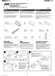
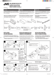
Installation/Connection Manual
Manuel d’installation/raccordement
GET0287-010A
1004DTSMDTJEIN
EN, FR
[EX/EU]
ENGLISH
FRANÇAIS
This receiver is designed to operate on 12 V DC, NEGATIVE ground electrical systems. If
your vehicle does not have this system, a voltage inverter is required, which can be purchased
at JVC IN-CAR ENTERTAINMENT dealers.
Cet appareil est conçu pour fonctionner sur des sources de courant continu de 12 V à masse
NEGATIVE. Si votre véhicule n’offre pas ce type d’alimentation, il vous faut un convertisseur de tension,
que vous pouvez acheter chez un revendeur d’autoradios JVC.
Parts list for installation and connection
Liste des pièces pour l’installation et raccordement
The following parts are provided for this receiver.
After checking them, please set them correctly.
Les pièces suivantes sont fournies avec cet appareil.
Après vérification, veuillez les placer correctement.
C
Sleeve
Manchon
A/B
Hard case/Control panel
Etui de transport/Panneau de
commande
F
Washer (ø5)
Rondelle (ø5)
H
Mounting bolt (M5 x 20 mm)
Boulon de montage (M5 x 20 mm)
G
Lock nut (M5)
Ecrou d’arrêt (M5)
E
Power cord
Cordon d’alimentation
D
Trim plate
Plaque d’assemblage
I
Rubber cushion
Amortisseur en caoutchouc
J
Handles
Poignées
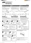
INSTALLATION (IN-DASH MOUNTING)
INSTALLATION (MONTAGE DANS LE TABLEAU DE BORD)
The following illustration shows a typical installation. If you have any questions or require
information regarding installation kits, consult your JVC IN-CAR ENTERTAINMENT dealer or a
company supplying kits.
• If you are not sure how to install this receiver correctly, have it installed by a qualified technician.
L’illustration suivante est un exemple d’installation typique. Si vous avez des questions ou avez besoin
d’information sur des kits d’installation, consulter votre revendeur d’autoradios JVC ou une compagnie
d’approvisionnement.
• Si l’on n’est pas sûr de pouvoir installer correctement cet appareil, le faire installer par un technicien qualifié.
Do the required electrical connections.
Réalisez les connexions électriques.
*1 When you stand the receiver, be
careful not to damage the fuse on
the rear.
*1 Lorsque vous mettez l’appareil à la
verticale, faire attention de ne pas
endommager le fusible situé sur l’arrière.
Removing the receiver / Retrait de l’appareil
Before removing the receiver, release the rear section.
Avant de retirer l’appareil, libérer la section arrière.
Bend the appropriate tabs to hold the
sleeve firmly in place.
Tordez les languettes appropriées pour
maintenir le manchon en place.
When using the optional stay / Lors
de l’utilisation du hauban en option
When installing the receiver without using the sleeve / Lors de
l’installation de l’appareil scans utiliser de manchon
In a Toyota for example, first remove the car radio and install the receiver in its place.
Stay
Par exemple dans une Toyota, retirer d’abord l’autoradio et installer l’appareil à la
(option)
place.
Hauban (en
* Not included for this
option)
receiver.
Flat type screws
* Non fourni avec cet appareil.
(M5 x 8 mm)*
Bracket*
Vis à tête plate
Support*
Screw (option)
(M5 x 8 mm)*
Flat type screws
Vis (en option)
(M5 x 8 mm)*
Vis à tête plate
Pocket
(M5 x 8 mm)*
Bracket*
Poche
Support*
Fire wall
Cloison
Dashboard
Tableau de
bord
Insert the two handles, then
pull them as illustrated so
that the receiver can be
removed.
Insérez les deux poignées, puis
tirez de la façon illustrée de
façon à retirer l’appareil.
Note
Install the receiver at an
angle of less than 30˚.
Installez l’appareil avec un
angle de moins de 30˚.
PRECAUTIONS on power supply and speaker
connections:
PRECAUTIONS sur l’alimentation et la connexion
des enceintes:
• DO NOT connect the speaker leads of the power cord to
the car battery; otherwise, the receiver will be seriously
damaged.
• BEFORE connecting the speaker leads of the power cord to the
speakers, check the speaker wiring in your car.
• NE CONNECTEZ PAS les fils d’enceintes du cordon
d’alimentation à la batterie; sinon, l’appareil serait
sérieusement endommagé.
• AVANT de connecter les fils d’enceintes du cordon d’alimentation aux
enceintes, vérifiez le câblage des enceintes de votre voiture.
EN CAS DE DIFFICULTES
TROUBLESHOOTING
•
*
•
*
•
*
•
*
*
•
*
•
*
*
•
*
: When installing the receiver on the mounting bracket, make
sure to use the 8 mm-long screws. If longer screws are
used, they could damage the receiver.
Remarque : Lors de l’installation de l’appareil sur le support de montage,
s’assurer d’utiliser des vis d’une longueur de 8 mm. Si des vis plus
longues sont utilisées, elles peuvent endommager l’appareil.
The fuse blows.
Are the red and black leads connected correctly?
Power cannot be turned on.
Is the yellow lead connected?
No sound from the speakers.
Is the speaker output lead short-circuited?
Sound is distorted.
Is the speaker output lead grounded?
Are the “–” terminals of L and R speakers grounded in common?
Noise interfere with sounds.
Is the rear ground terminal connected to the car’s chassis using shorter and thicker cords?
Receiver becomes hot.
Is the speaker output lead grounded?
Are the “–” terminals of L and R speakers grounded in common?
This receiver does not work at all.
Have you reset your receiver?
Instal1-2_S1501_010A_f.indd 2
•
*
•
*
•
*
•
*
*
•
*
•
*
*
•
*
Le fusible saute.
Les fils rouge et noir sont-ils racordés correctement?
L’appareil ne peut pas être mise sous tension.
Le fil jaune est-elle raccordée?
Pas de son des enceintes.
Le fil de sortie d’enceinte est-il court-circuité?
Le son est déformé.
Le fil de sortie d’enceinte est-il à la masse?
Les bornes “–” des enceintes gauche et droit sont-elles mises ensemble à la masse?
Interférence avec les sons.
La prise arrière de mise à la terre est-elle connectée au châssis de la voiture avec un cordon court et épais?
L’appareil devient chaud.
Le fil de sortie d’enceinte est-il à la masse?
Les bornes “–” des enceintes gauche et droit sont-elles mises ensemble à la masse?
Cet appareil ne fonctionne pas du tout.
Avez-vous réinitialisé votre appareil?
1
20/10/04, 12:18:50 PM
ENGLISH
FRANÇAIS
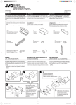
ELECTRICAL CONNECTIONS
RACCORDEMENTS ELECTRIQUES
To prevent short circuits, we recommend that you disconnect the battery’s negative terminal and
make all electrical connections before installing the receiver.
• Be sure to ground this receiver to the car’s chassis again after installation.
Pour éviter tout court-circuit, nous vous recommandons de débrancher la borne négative de la batterie et
d’effectuer tous les raccordements électriques avant d’installer l’appareil.
• Assurez-vous de raccorder de nouveau la mise à la masse de cet appareil au châssis
de la voiture après l’installation.
Notes:
• Replace the fuse with one of the specified rating. If the fuse blows frequently, consult your JVC
IN-CAR ENTERTAINMENT dealer.
• It is recommended to connect to the speakers with maximum power of more than 45 W (both
at the rear and at the front, with an impedance of 4 Ω to 8 Ω). If the maximum power is less
than 45 W, change “AMP GAIN” setting to prevent the speakers
from being damaged (see page 18 of the INSTRUCTIONS).
• To prevent short-circuit, cover the terminals of the UNUSED
leads with insulating tape.
Heat sink
• The heat sink becomes very hot after use. Be
Dissipateur
de chaleur
careful not to touch it when removing this receiver.
A
Remarques:
• Remplacer le fusible par un de la valeur précisée. Si le fusible saute souvent, consulter votre revendeur
d’autoradios JVC.
• Il est recommandé de connecter des enceintes avec une puissance de plus de 45 W (les enceintes arrière
et les enceintes avant, avec une impédance comprise entre 4 Ω et 8 Ω). Si la puissance maximum est
inférieure à 45 W, changez “AMP GAIN” pour éviter d’endommager vos enceintes (voir page 18 du
MANUEL D’INSTRUCTIONS).
• Pour éviter les court-circuits, couvrir les bornes des fils qui ne sont PAS UTILISÉS avec de la bande
isolante.
• Le dissipateur de chaleur devient très chaud après usage. Faire attention de ne pas le toucher en retirant
cet appareil.
Typical connections / Raccordements typiques
Before connecting: Check the wiring in the vehicle carefully. Incorrect connection may cause
serious damage to this receiver.
The leads of the power cord and those of the connector from the car body may be different in
color.
Avant de commencer la connexion: Vérifiez attentivement le câblage du véhicule. Une connexion
incorrecte peut endommager sérieusement l’appareil.
Le fil du cordon d’alimentation et ceux des connecteurs du châssis de la voiture peuvent être différents en
couleur.
1
2
3
1
2
3
Connect the colored leads of the power cord in the order specified in the illustration below.
Connect the aerial cord.
Finally connect the wiring harness to the receiver.
Note: If your vehicle does not have any accessory terminal, move the fuse from the fuse
position 1 (initial position) to fuse position 2, and connect the red lead (A7) to the positive (+)
battery terminal.
• The yellow lead (A4) is not used in this case.
Connectez les fils colorés du cordon d’alimentation dans l’ordre spécifié sur l’illustration ci-dessous.
Connectez le cordon d’antenne.
Finalement, connectez le faisceau de fils à l’appareil.
Remarque: Si votre véhicule ne possède pas de borne accessoire, déplacez le fusible de la position de
fusible 1 (position originale) à la position de fusible 2 et connectez le fil rouge (A7) à la borne positive
(+) de la batterie.
• Le fil jaune (A4) n’est pas utilisé dans ce cas.
To steering wheel remote controller—only for KD-S1501 (see diagram )
Pour la télécommande de volant—seulement pour le KD-S1501 (voir le diagramme
)
Fuse position 2 / Position de fusible 2
Rear ground
terminal
Borne arrière de
masse
Aerial terminal
Borne de l’antenne
Fuse position 1 / Position de fusible 1
Line out (see diagram
Sortie de ligne
(voir le diagramme )
*1 Not included for this receiver
*1 Non fourni avec cet appareil
15 A fuse
Fusible 15 A
)
Black
Noir
To metallic body or chassis of the car
Vers corps métallique ou châssis de la voiture
Yellow*2
Jaune*2
To a live terminal in the fuse block connecting to the car battery
(bypassing the ignition switch) (constant 12 V)
À une borne sous tension du porte-fusible connectée à la batterie de la voiture
(en dérivant l’interrupteur d’allumage) (12 V constant)
Red
Rouge
*2 Before checking the operation of this receiver
prior to installation, this lead must be connected,
otherwise power cannot be turned on.
*2 Pour vérifier le fonctionnement de cet appareil avant
installation, ce fil doit être raccordé, sinon l’appareil
ne peut pas être mis sous tension.
White with black stripe
Blanc avec bande noire
White
Blanc
Gray with black stripe
Gris avec bande noire
Left speaker (front)
Enceinte gauche (avant)
B
To an accessory terminal in the fuse block
Vers borne accessoire du porte-fusible
Blue with white stripe
Bleu avec bande blanche
Fuse block
Porte-fusible
To the remote lead of other equipment or power aerial if any (200 mA max.)
Au fil de télécommande de l’autre appareil ou à l’antenne automatique s’il y en a une
(200 mA max.)
Brown
Marron
To cellular phone system (only for KD-S1501)
À un système de téléphone cellulaire (seulement pour le KD-S1501)
Gray
Gris
Green with black stripe
Vert avec bande noire
Green
Vert
Right speaker (front)
Enceinte droit (avant)
Purple with black stripe
Violet avec bande noire
Left speaker (rear)
Enceinte gauche (arrière)
Purple
Violet
Right speaker (rear)
Enceinte droit (arrière)
Connecting the external amplifier / Connexion d’un amplificateur extérieur
You can connect an amplifier to upgrade your car stereo system.
• Connect the remote lead (blue with white stripe) to the remote lead of the other equipment so
that it can be controlled through this receiver.
• Disconnect the speakers from this receiver, connect them to the amplifier. Leave the
speaker leads of this receiver unused.
Rear speakers
Enceintes arrière
Remote lead
Fil d’alimentation à distance
JVC Amplifier
JVC
Amplificateur
Vous pouvez connecter un amplificateur pour améliorer votre système autoradio.
• Connectez le fil de commande à distance (bleu avec bande blanche) au fil de commande à distance de
l’autre appareil de façon qu’il puisse être commandé via cet appareil.
• Déconnectez les enceintes de cet appareil et connectez-les à l’amplificateur. Laissez
les fils d’enceintes de cet appareil inutilisés.
Y-connector (not supplied for this receiver)
Connecteur Y (non fourni avec cet appareil)
Remote lead (Blue with white stripe)
Fil d’alimentation à distance (Bleu avec bande blanche)
Signal cord (not supplied for this receiver)
Cordon de signal (non fourni avec cet appareil)
Front speakers
Enceintes avant
C
Ignition switch
Interrupteur d’allumage
To the remote lead of other equipment or power
aerial if any
Au fil de télécommande de l’autre appareil ou à l’antenne
automatique s’il y en a une
*3 Firmly attach the ground wire to the metallic
body or to the chassis of the car—to the place
not coated with paint (if coated with paint,
remove the paint before attaching the wire).
Failure to do so may cause damage to the
receiver.
*3 Attachez solidement le fil de mise à la masse au
châssis métallique de la voiture—à un endroit qui
n’est pas recouvert de peinture (s’il est recouvert
de peinture, enlevez d’abord la peinture avant
d’attacher le fil). L’appareil peut être endommagé si
cela n’est pas fait correctement.
Connecting to the steering wheel remote controller / Connexion de la télécommande de volant
Only for KD-S1501 / Seulement pour le KD-S1501
If your car is equipped with the steering wheel remote controller, you can operate this receiver using the
controller. To do it, a JVC’s OE remote adapter (not supplied) which matches with your car is required.
Consult your JVC IN-CAR ENTERTAINMENT dealer for details.
Si votre voiture est munie d’une télécommande de volant, vous pouvez commander cet autoradio en utilisant la
télécommande. Pour le faire, un adaptateur pour télécommande au volant JVC (non fourni) correspondant à votre
voiture est nécessaire. Consultez votre revendeur d’autoradio JVC pour les détails.
Steering wheel remote input
Entrée de la télécommande de volant
OE remote adapter (not supplied)
Adaptateur pour télécommande au volant (non fourni)
Steering wheel remote controller (equipped in the car)
Télécommande de volant (installée dans la voiture)
2
Instal1-2_S1501_010A_f.indd 3
10/16/04, 4:24:56 PM
Having TROUBLE with operation?
Please reset your unit
Refer to page of How to reset your unit
Vous avez des PROBLÈMES de fonctionnement?
Réinitialisez votre appareil
Référez-vous à la page intitulée Comment réinitialiser votre appareil
EN, FR
© 2004 Victor Company of Japan, Limited
Rear_KD-S1501[EX_EU]f.indd 2
1004DTSMDTJEIN
10/27/04 3:24:09 PM