1
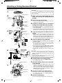
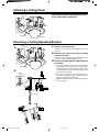
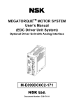
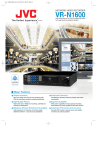
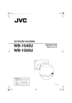
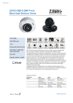
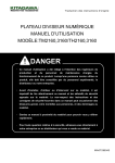
WB-S625U
Ceiling Recessed Bracket
INSTRUCTIONS
Thank you for purchasing this product.
To obtain the best results from your Ceiling Recessed Bracket, read these instructions carefully before use; retain the manual for future reference.
Instructions on installation are also described in this section. Please read through carefully before installation.
This instruction manual is made from recycled paper.
For Customer Use:
Enter below the Serial No. which is located on the body.
Retain this information for future reference.
Model No.
Serial No.
These are general IMPORTANT SAFEGUARDS and certain items may not apply to all appliances.
IMPORTANT SAFEGUARDS
1.
2.
3.
4.
5.
6.
7.
8.
9.
10.
11.
12.
13.
14.
15.
16.
17.
18.
Read all of these instructions.
Save these instructions for later use.
All warnings on the product and in the operating instructions should be adhered to.
Unplug this appliance system from the wall outlet before cleaning. Do not use liquid cleaners or aerosol cleaners. Use a damp cloth for
cleaning.
Do not use attachments not recommended by the appliance manufacturer as they may cause hazards.
Do not use this appliance near water - for example, near a bathtub, washbowl, kitchen sink, or laundry tub, in a wet basement, or near a
swimming pool, etc.
PORTABLE CART WARNING
Do not place this appliance on an unstable cart, stand, or table. The appliance may fall, causing serious injury to a child or (symbol provided by RETAC)
adult, and serious damage to the appliance may fall, causing serious injury to a child or adult, and serious damage to the
appliance.
Use only with a cart or stand recommended by the manufacturer, or sold with the appliance. Wall or shelf mounting should
follow the manufacturer’s instructions, and should use a mounting kit approved by the manufacturer.
An appliance and cart combination should be moved with care. Quick stops, excessive force, and uneven surfaces may
cause the appliance and cart combination to overturn.
Slots and openings in the cabinet and the back or bottom are provided for ventilation, and to insure reliable operation of
S3125A
the appliance and to protect it from overheating, these openings must not be blocked or covered. The openings should
never be blocked by placing the appliance on a bed, sofa, rug, or other similar surface. This appliance should never be placed near or over a
radiator or heat register. This appliance should not be placed in a built-in installation such as a bookcase unless proper ventilation is provided.
This appliance should be operated only from the type of power source indicated on the marking label. If you are not sure of the type of power
supplied to your home, consult your dealer or local power company. For appliance designed to operate from battery power, refer to the
operating instructions.
For added protection for this product during a lightning storm, or when it is left unattended and unused for long periods of time, unplug it from
the wall outlet and disconnect the antenna or cable system. This will prevent damage to the product due to lightning and power-line surges.
Do not allow anything to rest on the power cord. Do not locate this appliance where the cord will be abused by persons walking on it.
Follow all warnings and instructions marked on the appliance.
Do not overload wall outlets and extension cords as this can result in fire or electric shock.
Never push objects of any kind into his appliance through cabinet slots as they mat touch dangerous voltage points or short out parts that could
result in a fire or electric shock. Never spill liquid of any kind on the appliance.
Do not attempt to service this appliance yourself as opening or removing covers may expose you to dangerous voltage or other hazards. Refer
all servicing to qualified service personnel.
Unplug his appliance from the wall outlet and refer servicing to qualified service personnel under following conditions:
a. When the power cord or plug is damaged or frayed.
b. If liquid has been spilled into the appliance.
c. If the appliance has been exposed to rain or water.
d. If the appliance does not operate normally by following the operating instructions. Adjust only those controls that are covered by the operating
instructions as improper adjustment of other controls may result in damage and will often require extensive work by a qualified technician to
restore the appliance to normal operation.
e. If the appliance has been dropped or the cabinet has been damaged.
f. When the appliance exhibits a distinct change in performance - this indicates a need for service.
When replacement parts are required, be sure the service technician has used replacement parts specified by the manufacturer that have the
same characteristics as the original part. Unauthorized substitutions may result in fire, electric shock, or other hazards.
Upon completion of any service or repairs to this appliance, ask the service technician to perform routine safety checks to determine that the
appliance is in safe operating condition.
For USA and CANADA
CAUTION
RISK OF ELECTRIC
SHOCK DO NOT OPEN
CAUTION: TO REDUCE THE RISK OF ELECTRIC SHOCK.
DO NOT REMOVE COVER (OR BACK).
NO USER SERVICEABLE PARTS INSIDE.
REFER SERVICING TO QUALIFIED SERVICE PERSONNEL.
The lightning flash with arrowhead symbol, within an equi-lateral triangle, is
intended to alert the user to the presence of uninsulated “dangerous voltage”
within the product’s enclosure that may be of sufficient magnitude to constitute
a risk of electric shock to persons.
The exclamation point within an equilateral triangle is intended to alert the user
to the presence of important operating and maintenance (servicing) instructions in the literature accompanying the appliance.
WB-S625U_LWT0270-001A-K
1
WARNING:
TO PREVENT FIRE OR SHOCK HAZARD, DO NOT
EXPOSE THIS UNIT TO RAIN OR MOISTURE.
Information for USA
This device complies with Part 15 of the FCC Rules.
Changes or modifications not approved by JVC could void the user’s authority to operate the equipment.
INFORMATION (FOR CANADA) RENSEIGNEMENT (POUR
LE CANADA)
This Class [B] digital apparatus complies with Canadian ICES-003.
Cet appareil numérique de la classe [B] est conforme à la norme NMB-003
du Canada.
Due to design modification, data given in this instruction
book are subject to possible change without prior notice.
05.3.18, 10:44 AM
Attaching a Ceiling Recessed Bracket
In the case of VN-C625U, install the Converter Unit (supplied with VN-C625U) in the ceiling before mounting the
Ceiling Recessed Bracket.
CAUTION
1.
165(6 1/2
inch)
The Ceiling Recessed Bracket can be mounted to ceiling
materials with a thickness between 5 mm to 31 mm (1/4
inch to 1 1/4 inch).
Alignment Mark (&)
2.
1.
Mounting
screws
(4 locations)
2.
3.
Clamping
screws
(3 locations)
3.
Anchor bolt
mount hole
4.
5.
Stopper
Anchor bolt
5.
When anchor
bolts cannot
be used
Hexagon Nut
Insert the Ceiling Recessed Bracket into the
ceiling.
● Align the & mark on the Ceiling Recessed Bracket in the
direction that you want the camera to face, and insert the
Ceiling Recessed Bracket into the ceiling by tilting it as shown
in the diagram. The stopper will press against the rear of
the ceiling and hold the Ceiling Recessed Bracket in place.
Alignment Mark (&)
Side chart
Perform the following prior to inserting the
Ceiling Recessed Bracket into the ceiling.
● Check that the orientation of the clamping bracket is as
shown in the diagram.
● If the clamping bracket is not installed all the way up, do
so by turning the clamping screws of the Ceiling Recessed
Bracket in the counter-clockwise direction. (3 locations)
Screw driver
Ceiling
Recessed
Bracket
Upper
chart
Remove the mounting screws.
● Use these mounting screws (4 locations) to mount the
ceiling mount of the camera.
Clamping
brackets
4.
Make a hole in the ceiling (φ165 mm (6 1/2
inch)) for inserting the Ceiling Recessed
Bracket.
Fasten the Ceiling recessed Bracket.
● Push the Ceiling Recessed Bracket all the way upward
towards the ceiling.
● Turn the clamping screws in the counter-clockwise direction, and fasten upon clamping the ceiling material with
the clamping bracket. (3 locations)
● If anchor bolts can be used, attach M8 to M10 (or 3/8 inch)
anchor bolts into the anchor bolt mount hole on the Ceiling
Recessed Bracket and tighten using a hexagon nut.
● If anchor bolts cannot be used, ensure to install a safety
cable.
CAUTION
● Make sure that the clamping blackets grip the ceiling plate
firmly. If the Ceiling Recessed Bracket rattles after the
clamping screws.
● For the used safety cable, pay particular caution to the
length, strength, pull, material, etc.
Safety cable
6.
● For details, please refer to the “INSTRUCTIONS” section of the camera in use.
Clamping brackets
Alignment Mark (&)
7.
Front Mark (•)
8.
Attach the camera to the Ceiling mount.
9.
Attach the Ceiling Panel.
Ceiling mount
WB-S625U_LWT0270-001A-K
2
Attach the Ceiling mount to the Ceiling Recessed Bracket.
● Attach the ceiling mount supplied with the camera to the
Ceiling Recessed Bracket, be careful not to catch the
cables. Use the mounting screws (4 locations) that have
been removed in Step 2. When attaching, align the
FRONT mark (•) of the ceiling mount with the & mark of
the Ceiling Recessed Bracket.
7.
Mounting screws
(4 locations)
Connect cables to the Ceiling mount.
● Perform the necessary camera settings before attaching.
● For details, please refer to the “INSTRUCTIONS” section of the camera in use.
● Refer to “Attaching a Ceiling Panel” on the next page.
05.3.18, 10:45 AM
Attaching a Ceiling Panel
Hooks
(2 locations)
Attach the ceiling panel (supplied) to the 2 hooks
on the Ceiling Recessed Bracket.
Ceiling
Ceiling Panel
Camera
Removing a Ceiling Recessed Bracket
Hooks
(2 locations)
1.
1.
Remove the Ceiling Panel.
Pull down the Ceiling Panel and disengage the 2 hooks
either side.
2.
Dismount the camera unit from the Ceiling
Recessed Bracket.
To dismount, reverse the procedures for “Attaching the Camera” in the camera’s “INSTRUCTIONS” section.
3.
Dismount the Ceiling Recessed Bracket from
the ceiling.
1 Loosen the clamping screws (3 locations) while supporting the Ceiling Recessed Bracket. Upon ensuring that the
clamping bracket has been dismounted from the ceiling,
lower the Ceiling Recessed Bracket until the stopper comes
into contact with the ceiling.
Ceiling Panel
3.
Stopper
release lever
2 To remove the stopper from the ceiling, push the stopper release lever upwards using a screwdriver while supporting the Ceiling Recessed Bracket.
Stopper
3 Support the tilted Ceiling Recessed Bracket and remove
it from the ceiling.
Push
Upwards
2
Clamping screw
(3 locations)
1
Screw driver
3
WB-S625U_LWT0270-001A-K
3
05.3.18, 10:45 AM
Specifications
q Operating temperature : -10 ˚C to 50 ˚C
q Accessories
: · Instructions ................................... 1
· Ceiling Panel ................................. 1
(14 ˚F to 122 ˚F)
q Mass
: 0.6 k˝
q External dimensions [Unit : mm (inches) ]
● WB-S625U
(Ceiling Recessed Bracket+Ceiling Panel)
● WB-S625U Ceiling mount hole
(Ceiling thickness : 5 mm to 31 mm (1/4 to 1 1/4)
Hole making size
2)
6
5(
1/
Anchor bolt mount hole
6
φ1
Ceiling Panel
50(2)
Anchor bolt Compatible with
M8 to M10 (or 3/8 inch)
119(4 5/8)
167(6 5/8)
5 mm – 31 mm
(1/4 – 1 1/4)
Ceiling Thickness
φ165(6 1/2)
(Hole making size)
φ200(7 7/8)
*Design and specifications are subject to change without notice.
is a Registered Trademark owned by Victor Company of Japan, Limited.
is a Registered Trademark in Japan, the U.S.A., the U.K. and many other countries.
© 2005 Victor Company of Japan, Limited
WB-S625U_LWT0270-001A-K
4
05.3.18, 0:59 PM
Printed in Korea
LWT0270-001A-K