1
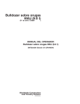
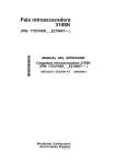
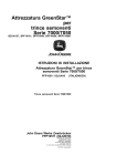
AutoTrac Universal (ATU) Steering Kit INSTALLATION INSTRUCTIONS PC20864 05JUL07 (ENGLISH) John Deere Ag Management Solutions PC20864 (05JUL07) COPYRIGHT 2007 DEERE & COMPANY Moline, Illinois All rights reserved A John Deere ILLUSTRUCTION Manual PC20864-19-05JUL07 Installation Instructions Overview sold separately from the AutoTrac Universal Steering Kit. Installation of the GreenStar system is dependent on the vehicle it is being installed on. Newer John Deere vehicles come with the harness already installed. AutoTrac Universal system requires the GreenStar system to operate. The two systems consist of the following components: • GreenStar – Receiver – Processor – Display – Harness • AutoTrac Universal – AutoTrac Universal Steering Wheel – Shaft Bushing – AutoTrac Universal Harness – Anti-Rotational Device The GreenStar System AutoTrac Universal System This system is an easy-to-install guidance system that works similar to the integrated system, but instead of directly controlling the hydraulics that steer the machine, the AutoTrac Universal system turns the steering wheel, guiding the machine using the same mechanisms that a person would. Because AutoTrac Universal isn’t integrated into the steering system: This system consists of a receiver, a processor, and a display, connected by a harness. On the new GS2 system, the display and processor are combined into a single unit. The GreenStar system is the backbone for many processes such as recording harvest yields, setting planter and chemical application rates, and mapping acres covered. Because the GreenStar system is utilized by so many different processes, it is • It is compatible with a large number of different machines. See your John Deere dealer for a list of approved platforms. • Accuracy is affected by wear on any part of the steering system. OUO6050,0000A49 –19–25MAY07–1/1 PC20864 (05JUL07) 1 Installation Instructions 070507 PN=3 Installation Instructions PC9156B –UN–29MAY07 AutoTrac Universal 200 Steering Kit A—AutoTrac Universal Steering Wheel B—AutoTrac Universal Harness C—Operator Presence Harness (Optional) D—Cover Used with Anti-Rotation Bracket (M) E—Steering Wheel Knob (Used to telescope steering wheel) F—Steering Wheel Cap Cover G—Adhesive Harness Clips H—Screws for Anti-Rotational Device This is the basic AutoTrac Universal Steering Kit including parts for a variety of different machine. The I—Wrench J—On/Off Switch (Europe Only) K—Auxiliary Resume Switch kit also includes shims, locking washer, telescoping washers, and manuals. OUO6050,0000A4A –19–15JUN07–1/1 PC20864 (05JUL07) 2 Installation Instructions 070507 PN=4 Installation Instructions Installation of the AutoTrac Universal system Installation involves the following steps: 6. Europe Only—Attach On/Off Switch 7. Attach AutoTrac Universal Harness to GreenStar Harness 8. Attach Seat Switch Harness—if applicable 9. Route and Secure All Harnesses 10. Activate AutoTrac Universal 11. Setup System 1. 2. 3. 4. Remove the Steering Wheel. Attach Bushing Attach Anti-Rotational Device Attach AutoTrac Universal Steering Wheel to Steering Shaft 5. Attach AutoTrac Universal Harness to AutoTrac Universal Steering Wheel OUO6050,0000A4C –19–25MAY07–1/1 The steering wheel should be removed following the process set by the manufacturer of the machine. The hardware shown is specific to John Deere tractors. Depending on the machine, the hardware attaching the steering wheel may be different. Save hardware and use it to attach the AutoTrac Universal Steering Wheel. Save original steering wheel to use if AutoTrac Universal is removed from machine. PC8716 A—Locking Washer B—Lock Nut C—Telescoping Washers D—Nut –UN–08SEP05 Remove Steering Wheel OUO6050,0000A4D –19–25MAY07–1/1 PC20864 (05JUL07) 3 Installation Instructions 070507 PN=5 Installation Instructions Attach Bushing A range of bushings have been created to allow the AutoTrac Universal Steering Wheel to fit on shafts that vary in style and dimension. Select the proper bushing and insert it into the AutoTrac Universal steering wheel. Attaching the bushing with a snap ring. For vehicle specific information visit www.StellarSupport.com. NOTE: Be sure that the hole for lock washer is facing towards steering wheel before securing snap ring. Lubricate bushing before installation to prevent corrosion. PC9009 –UN–04APR06 A—Bushing B—Snap Ring OUO6050,0000A4E –19–25MAY07–1/1 Attach Anti-Rotational Devices There are different types of anti-rotational devices. Make sure that you are using the proper type of anti-rotational device AND the correct design specific to your machine. For vehicle specific information visit www.StellarSupport.com. The following are two examples of anti-rotational devices. Continued on next page PC20864 (05JUL07) 4 OUO6050,0000A4F –19–31MAY07–1/3 Installation Instructions 070507 PN=6 PC8750 –UN–19OCT05 Installation Instructions A—U-bolt, Saddle, Spacer, Pillow-Block and Nuts B—Anti-Rotation Rod Assembly C—Screws D—Cover (1) Clamp and Rod Anti-Rotational Device E—Screw 3. Attach cover (D) to steering unit assembly with screw (E). IMPORTANT: To allow steering wheel to telescope normally, install assembly (A) near top end of steering column as shown in diagram. 4. Attach steering unit to vehicle steering shaft by inserting rod (B) into pillow-block assembly and pressing ball plunger on rod to allow it to pass through. 1. Attach U-bolt, saddle, spacer, pillow-block and nuts (A) near top of steering shaft base. 2. Attach anti-rotation rod assembly (B) to bottom of steering unit base plate with screws (C). Continued on next page PC20864 (05JUL07) 5 OUO6050,0000A4F –19–31MAY07–2/3 Installation Instructions 070507 PN=7 PC8771 –UN–21DEC06 –UN–14OCT05 Installation Instructions PC9154A Shims A—Anti-Rotation Bracket B—Steering Unit C—Screw (2 Used) (2) Console Anti-Rotation Device if optimal performance can not be attained through changes in the vehicle sensitivity settings. Attach anti-rotation bracket (A) to steering unit (B) with screws (C). Use slots to move bracket snug against column. When using Console Anti-Rotation Device, shims may be required to eliminate movement in the vehicle’s steering console. Shims should only be used IMPORTANT: Use of shims will eliminate the ability of the steering column to telescope. OUO6050,0000A4F –19–31MAY07–3/3 PC20864 (05JUL07) 6 Installation Instructions 070507 PN=8 Installation Instructions Attach AutoTrac Universal Steering Wheel to Shaft Position AutoTrac Universal steering wheel on steering column. The hardware shown is specific to John Deere tractors. The hardware attaching the AutoTrac Universal steering wheel may be different. Use hardware from the removal of the original steering wheel to attach the AutoTrac Universal steering wheel. IMPORTANT: Tighten all hardware to proper torque according to vehicle manufacturer’s specifications. 1. Attach lock washer (A), and nut (B) to steering wheel rod. –UN–04APR06 2. Attach washer (C), knob (D), washer (E), and nut (F) on telescoping rod. 3. Insert cap (G) into knob. PC9011 A—Lock Washer B—Nut C—Washer D—Telescoping Knob E—Washer F—Telescoping Rod Nut G—Cap OUO6050,0000A51 –19–25MAY07–1/1 Attach AutoTrac Universal Harness to AutoTrac Universal Steering Wheel Connect 9-pin harness from AutoTrac Universal steering wheel (A) to AutoTrac Universal harness (B). PC8772 –UN–14OCT05 A—9-pin harness from AutoTrac Universal Steering Wheel B—AutoTrac Universal Harness OUO6050,0000A52 –19–25MAY07–1/1 PC20864 (05JUL07) 7 Installation Instructions 070507 PN=9 Installation Instructions Europe Only—Attach On/Off Switch Connect On/Off Switch (B) to AutoTrac Universal Harness (C). PC8896 Motor power needs to be shut off during public road transportation. –UN–02JAN06 Connect 9-pin harness from AutoTrac Universal steering wheel (A) to On/Off switch (B). A—9-pin harness from AutoTrac Universal Steering Wheel B—On/Off Switch C—AutoTrac Universal Harness OUO6050,0000A53 –19–25MAY07–1/1 PC20864 (05JUL07) 8 Installation Instructions 070507 PN=10 Installation Instructions Attach AutoTrac Universal Harness to GreenStar Harness –UN–19OCT05 Depending on your vehicle’s harness configuration, the AutoTrac Universal harness will be connected to the GreenStar harness at one of the following locations: GreenStar Ready Vehicles PC8718 Vehicles that are GreenStar Ready (or vehicles that have GreenStar harnesses already installed) can be connected at one of the following locations: Routing and Installation View • 2- and 4- pin terminator connectors found at the CAN bus extension (A) in the side console of a GreenStar Ready tractor. A—CAN Bus Extension B—Implement Connector • If equipped with an Implement Connector the AutoTrac Universal harness can be connected at the 2- and 4pin connectors on the implement connector (B). NOTE: FOR TRACTORS EQUIPPED WITH A TECU: Implement connector can not be used as the source of the 2-pin power on machines equipped with TECU. In NA, SA and AU—Order a ’2-pin to Convenience Outlet adapter harness (PF80873)’ from Service Parts. A second adapter harness (RE67015) can also be purchased from Service Parts to obtain power from a power strip. In Europe—Order a ’2-pin to COBO Outlet adapter harness (PF80874)’ from Service Parts. PF80873 and PF80874 plugs into the 2-pin connector on the ATU harness. • If the platform already has a GreenStar Harness, the 2-pin and 4-pin connectors on the ATU harness can be connected to the terminator connectors as shown on next page. Continued on next page PC20864 (05JUL07) 9 OUO6050,0000A54 –19–25MAY07–1/3 Installation Instructions 070507 PN=11 Installation Instructions a. Locate terminator with 2- and 4- pin connector. b. Disconnect terminator connections. PC8778 –UN–14OCT05 A—Terminator B—2-pin Connector C—4-pin Connector D—ATU Harness Connectors OUO6050,0000A54 –19–25MAY07–2/3 c. Connect ATU harness into terminator connectors and remaining GreenStar harness connectors into the remaining ATU harness connectors as shown. Non-GreenStar Ready Vehicles • Vehicles which are adding the GreenStar harness for the first time can connect directly into the GreenStar harness at the 2- and 4- pin terminator connectors. PC8779 –UN–18OCT05 NOTE: Depending upon the type of harness encountered, the size and color of the terminators may vary. OUO6050,0000A54 –19–25MAY07–3/3 PC20864 (05JUL07) 10 Installation Instructions 070507 PN=12 Installation Instructions PC8777 –UN–18OCT05 PC8721 –UN–23AUG05 Attach Seat Switch Harness A—Seat Switch Harness Connector to AutoTrac Universal Harness B—AutoTrac Universal Harness to Seat Switch Connector C—Connectors from Harness to Seat Switch 2. Connect seat switch harness connector to seat switch. This harness includes two sets of connectors, use only the set of connectors that corresponds with the vehicle’s seat switch. Disregard the unused set. NOTE: For John Deere Tractors equipped with an electronic seat switch, operator should connect into this switch as a mode of operator presence detection. Operators with other vehicles may be required to select “Activity Monitor” under Setup - AutoTrac and will have to interact regularly with the system in order to keep AutoTrac engaged. Goto www.StellarSupport.com for platform specific information relating to your specific vehicle. NOTE: Seat Switch is found on lower backside of the seat. 3. Plug unused connectors in to each other for dust protection 1. To connect seat switch, begin by connecting seat switch harness 4-pin round connector (A) to AutoTrac Universal harness 4-pin round connector (B). OUO6050,0000A56 –19–25MAY07–1/1 PC20864 (05JUL07) 11 Installation Instructions 070507 PN=13 Installation Instructions Route and Secures All Harnesses In order to prevent interference with operator and cab controls secure and route harnesses with the provided adhesive clips. 1. Thoroughly clean surface with JD All-Purpose Cleaner (TY25683) and dry completely before attaching adhesive clips. –UN–22NOV05 2. After removing protective film on the clips, press and hold the clips to the surface for at least 30 seconds to ensure proper adhesion. PC8873 3. Securely lock all harnesses into clips leaving enough slack for the steering wheel to telescope. OUO6050,0000A57 –19–25MAY07–1/1 PC20864 (05JUL07) 12 Installation Instructions 070507 PN=14 Installation Instructions PC10056 –UN–21JUN07 Activate AutoTrac Universal PC8782 –19–19OCT05 No ATU Activation, ATU has not been activated. Enter an activation code below or disconnect the ATU unit to access the GreenStar 2 Pro Application. AutoTrac Universal has to be activated by a 3-digit activation code the first time that it is powered up. The code can be attained by visiting www.StellarSupport.com or your local dealer. After obtaining activation code, power up AutoTrac Universal, enter the 3 digit activation code, and press SUBMIT. NOTE: Activation code may come with leading zeroes that do not need to be to entered. IMPORTANT: AutoTrac Universal serial number will be required to obtain activation code. OUO6050,0000A58 –19–21JUN07–1/1 Setup System See ATU Operator’s Manual for system setup. OUO6050,0000A59 –19–31MAY07–1/1 PC20864 (05JUL07) 13 Installation Instructions 070507 PN=15 Installation Instructions Harness Connection location in GreenStar Ready Tractor Side Consoles 1. Remove and retain screw (A) and spacer (B). –UN–30AUG05 2. Remove and disconnect panels (C and D). PC8731 A—Screw B—Spacer C—Panel D—Panel OUO6050,0000A55 –19–31MAY07–1/6 PC8719 –UN–23AUG05 NOTE: Some vehicles may allow enough space for connectors to slide down between window and side console. Continued on next page PC20864 (05JUL07) 14 OUO6050,0000A55 –19–31MAY07–2/6 Installation Instructions 070507 PN=16 Installation Instructions 3. Locate and disconnect GreenStar wiring harness 2and 4-pin connectors. NOTE: Connectors may be difficult to locate as they are often deep down in the console. PC8774 –UN–14OCT05 A—2-pin Connector B—4-pin Connector 2- and 4- pin Connectors OUO6050,0000A55 –19–31MAY07–3/6 4. Connect AutoTrac Universal harness to 2- and 4-pin connectors as shown. PC8775 –UN–14OCT05 IMPORTANT: Be sure to make all 4 connections as shown in photo at right. OUO6050,0000A55 –19–31MAY07–4/6 NOTE: See machine’s Technical Manual for removing and installing bottom console wrap. For ease of routing remove fuse panel cover. –UN–30AUG05 5. Route ATU harness between console and window towards floor behind fuse panel. PC8732 6. Pull back floor mat and continue to route ATU harness to steering motor connector. Continued on next page PC20864 (05JUL07) 15 OUO6050,0000A55 –19–31MAY07–5/6 Installation Instructions 070507 PN=17 Installation Instructions 7. Reinstall panels (C and D), retain with spacer (B) and screw (A). 8. Reinstall fuse panel cover and console wrap. PC8731 –UN–30AUG05 A—Screw B—Spacer C—Panel D—Panel OUO6050,0000A55 –19–31MAY07–6/6 Connect to a GreenStar Harness Terminator 1. Locate terminator with two- and four-pin connector. PC8778 –UN–14OCT05 2. Disconnect terminator connections. Continued on next page PC20864 (05JUL07) 16 OUO6050,0000A7E –19–31MAY07–1/2 Installation Instructions 070507 PN=18 Installation Instructions PC8779 –UN–18OCT05 3. Connect ATU harness into terminator connectors and remaining GreenStar harness connectors into the remaining ATU harness connectors as shown. OUO6050,0000A7E –19–31MAY07–2/2 Auxiliary Resume Switch Theory of Operation –UN–13SEP06 The ATU Auxiliary Resume Switch assembly was designed to allow ATU operators the ability to resume AutoTrac operation using a switch that can be mounted in a suitable location in the cab or operator’s station. The switch cover can either be mounted directly to a rigid surface or can be disassembled to allow panel mounting. PC9303B A—Resume Switch with cover B—Harness C—9-pin Round Connectors Continued on next page PC20864 (05JUL07) 17 OUO6050,0000A80 –19–05JUL07–1/3 Installation Instructions 070507 PN=19 Installation Instructions Switch Cover Direct Mounting: 1. Find a suitable location in the cab or operator’s station for the assembly to be mounted that will be out of the way of normal vehicle operation. NOTE: Harnessing will also need to be routed so it does not interfere with any vehicle functions performed by the operator. Use clips provided to secure harnesses. –UN–11AUG06 2. Mark and drill pilot holes using a 5mm (3/16’) drill bit for each of the two mounting holes in the assembly. PC9304 IMPORTANT: Use caution when drilling into a panel so that hidden wires or controls are not damaged. 3. Attach the assembly using the screws provided and ensure the assembly is rigid. Auxiliary Resume Switch 4. Connect the harness to the ATU harness at the 9-pin round connector. 5. Test switch functionality using the ATU diagnostic screens to ensure proper operation. A—Switch B—Front Case C—Rear Case D—Screws that hold Case Together (4 Used) E—Bolts that connect Case to Vehicle (2 Used) NOTE: The switch direction can be changed by disassembling the plastic enclosure and flipping the switch mount direction if necessary. Panel Mounting: 1. Find a suitable panel mount location in the cab or operator’s station for the switch that will be out of the way of normal vehicle operation. NOTE: Harnessing will also need to be routed so it does not interfere with any vehicle functions performed by the operator. Use clips provided to secure harnesses. 2. Disassemble the switch from the plastic enclosure by removing the (4) screws. Continued on next page PC20864 (05JUL07) 18 OUO6050,0000A80 –19–05JUL07–2/3 Installation Instructions 070507 PN=20 Installation Instructions 3. Re-assemble plastic switch enclosure and use hole where switch was as a guide for making hole in next step. 4. Create the panel mount hole if not already created (22mm X 36.8mm rectangular hole). 5. Insert the switch into the panel mount. NOTE: This may require disconnecting the harness from the switch. 6. Connect the harness to the ATU harness at the 9-Pin round connector. 7. Test switch functionality using the ATU diagnostic screens to ensure proper operation. OUO6050,0000A80 –19–05JUL07–3/3 PC20864 (05JUL07) 19 Installation Instructions 070507 PN=21 Installation Instructions PC20864 (05JUL07) 20 Installation Instructions 070507 PN=22