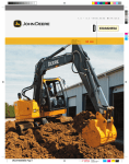
Download John Deere Products & Services 75C User's Manual
Transcript
7 . 5
C
75C
M E T R I C
EXCAVATOR
T O N
Specifications
Engine
75C
Type . . . . . . . . . . . . . . . . . . . . . . . . . . . . . . . . . . . Isuzu CC-4JG1 – naturally aspirated direct-injection diesel; certified to EPA Tier 2 emissions
Net Peak Power (ISO9249) . . . . . . . . . . . . . . . . . . 54 hp (40 kW) @ 2,100 rpm
Net Peak Torque (ISO9249) . . . . . . . . . . . . . . . . . . 142 lb.-ft. (192 Nm) @ 1,700 rpm
Cylinders . . . . . . . . . . . . . . . . . . . . . . . . . . . . . . . . 4
Displacement . . . . . . . . . . . . . . . . . . . . . . . . . . . . 187 cu. in. (3.059 L)
Cooling Fan . . . . . . . . . . . . . . . . . . . . . . . . . . . . . . suction type
Electrical System. . . . . . . . . . . . . . . . . . . . . . . . . . 24 volt with 30-amp alternator
Batteries (two 12 volt) . . . . . . . . . . . . . . . . . . . . . . reserve capacity: 100 min.
Off-Level Capacity. . . . . . . . . . . . . . . . . . . . . . . . . 70% (35 deg.)
Hydraulic System
Main Pumps . . . . . . . . . . . . . . . . . . . . . . . . . . . . . two variable-displacement axial-piston
Maximum Flow . . . . . . . . . . . . . . . . . . . . . . . . 2 x 18.3 gpm (2 x 69.3 L/min.)
Swing Gear Pump . . . . . . . . . . . . . . . . . . . . . . . . . 13.9 gpm (52.5 L/min.)
Pilot Pump. . . . . . . . . . . . . . . . . . . . . . . . . . . . . . . one gear
Maximum Flow . . . . . . . . . . . . . . . . . . . . . . . . 5.9 gpm (22.5 L/min.)
Pressure Setting . . . . . . . . . . . . . . . . . . . . . . . 570 psi (3930 kPa)
Dozer Blade Pump. . . . . . . . . . . . . . . . . . . . . . . . . one gear
System Operating Pressure
Implement Circuits . . . . . . . . . . . . . . . . . . . . . 3,770 psi (25 988 kPa)
Travel Circuits . . . . . . . . . . . . . . . . . . . . . . . . . 4,550 psi (31 380 kPa)
Swing Circuits. . . . . . . . . . . . . . . . . . . . . . . . . 3,270 psi (22 546 kPa)
Blade Circuit . . . . . . . . . . . . . . . . . . . . . . . . . . . . . 3,770 psi (25 988 kPa)
Oil Filtration. . . . . . . . . . . . . . . . . . . . . . . . . . . . . . one 10-micron full-flow return filter with by-pass / one pilot oil filter / one suction filter
Cylinders
Bore
Boom (1) . . . . . . . . . . . . . . . . . . . . . . . . . . . . . . . . 4.5 in. (115 mm)
Arm (1) . . . . . . . . . . . . . . . . . . . . . . . . . . . . . . . . . 3.7 in. (95 mm)
Bucket (1) . . . . . . . . . . . . . . . . . . . . . . . . . . . . . . . 3.3 in. (85 mm)
Rod Diameter
2.6 in. (65 mm)
2.4 in. (60 mm)
2.2 in. (55 mm)
Swing Mechanism
Swing Speed . . . . . . . . . . . . . . . . . . . . . . . . . . . . . 0–11 rpm
Swing Torque . . . . . . . . . . . . . . . . . . . . . . . . . . . . 10,200 lb.-ft. (13 840 Nm)
Undercarriage
Carrier Rollers (per side) . . . . . . . . . . . . . . . . . . . . 1
Track Rollers (per side) . . . . . . . . . . . . . . . . . . . . . 5
Idlers (per side) . . . . . . . . . . . . . . . . . . . . . . . . . . . 1
Shoes, Triple Semi-Grouser (per side) . . . . . . . . . . 40
Track Guides . . . . . . . . . . . . . . . . . . . . . . . . . . . . . front
Track Adjustment. . . . . . . . . . . . . . . . . . . . . . . . . . hydraulic
Travel Speed
Low. . . . . . . . . . . . . . . . . . . . . . . . . . . . . . . . . 0–2.1 mph (0–3.3 km/h)
High . . . . . . . . . . . . . . . . . . . . . . . . . . . . . . . . 0–3.1 mph (0–5.0 km/h)
Drawbar Pull . . . . . . . . . . . . . . . . . . . . . . . . . . . . . 12,350 lb. (5602 kg)
PAGES
2–3
Stroke
34.8 in. (885 mm)
35.4 in. (900 mm)
28.7 in. (730 mm)
Ground Pressure Data
75C
Average Ground Pressure
24-in. (600 mm) Triple Semi-Grouser Shoes
(recommended for general/soft terrain) . . . 3.53 psi (24.34 kPa)
18-in. (4450 mm) Rubber Crawler Pads
(recommended for street use only) . . . . . . 4.65 psi (32.06 kPa)
Capacities (U.S.)
Fuel Tank. . . . . . . . . . . . . . . . . . . . . . . . . . . . . . . . 31.7 gal. (120 L)
Cooling System . . . . . . . . . . . . . . . . . . . . . . . . . . . 6.1 qt. (5.8 L)
Engine Lubrication, Including Filter . . . . . . . . . . . . 10.5 qt. (9.9 L)
Hydraulic Tank. . . . . . . . . . . . . . . . . . . . . . . . . . . . 15.5 gal. (58.7 L)
Hydraulic System . . . . . . . . . . . . . . . . . . . . . . . . . 26.4 gal. (100 L)
Propel Gearbox (each) . . . . . . . . . . . . . . . . . . . . . . 2.6 qt. (2.5 L)
SAE Operating Weights
With Full Fuel Tank; 175-lb. (79 kg) Operator;
0.36-cu.-yd. (0.28 m3), 30-in. (750 mm),
522-lb. (237 kg) Bucket; 6-ft. 11-in. (2.12 m)
Arm; 3,042-lb. (1380 kg) Counterweight;
24-in. (600 mm) Triple Semi-Grouser Shoes;
and Backfill Blade . . . . . . . . . . . . . . . . . . . . . . 17,714 lb. (8035 kg)
Component Weights
Undercarriage
24-in. (600 mm) Triple Semi-Grouser Shoes . . . 6,481 lb. (2940 kg)
18-in. (450 mm) Rubber Crawler Pads . . . . . . 6,261 lb. (2840 kg)
Standard One-Piece Boom (with boom and
arm cylinders) . . . . . . . . . . . . . . . . . . . . . . . . . 1,082 lb. (491 kg)
Boom Cylinder Only. . . . . . . . . . . . . . . . . . . . . . . . 203 lb. (92 kg)
Arm with Bucket Cylinder and Linkage
5 ft. 4 in. (1.62 m). . . . . . . . . . . . . . . . . . . . . . 567 lb. (257 kg)
6 ft. 11 in. (2.12 m). . . . . . . . . . . . . . . . . . . . . 653 lb. (296 kg)
Counterweight. . . . . . . . . . . . . . . . . . . . . . . . . . . . 3,042 lb. (1380 kg)
0.36-cu.-yd. (0.28 m3), 30-in. (750 mm) Bucket . . . 522 lb. (237 kg)
Arm Length
5 ft. 4 in. (1.62 m)
Arm Force with 30-in. (750 mm), 0.36-cu.-yd.
(0.28 m3), 522-lb. (237 kg) Heavy-Duty
Bucket . . . . . . . . . . . . . . . . . . . . . . . . . . . . . . 8,425 lb. (37.5 kN)
Bucket Digging Force with 30-in. (750 mm),
0.36-cu.-yd. (0.28 m3), 522-lb. (237 kg)
Heavy-Duty Bucket . . . . . . . . . . . . . . . . . . . . . 11,220 lb. (49.9 kN)
Lifting Capacity Over Front @ Ground Level
15-ft. (4.57 m) Reach . . . . . . . . . . . . . . . . . . . 2,988 lb. (1355 kg)
A Maximum Reach . . . . . . . . . . . . . . . . . . . . . . 21 ft. 1 in. (6.43 m)
A' Maximum Reach @ Ground Level . . . . . . . . . 20 ft. 6 in. (6.26 m)
B Maximum Digging Depth . . . . . . . . . . . . . . . . 13 ft. 6 in. (4.11 m)
B' Maximum Digging Depth @ 8-ft. (2.44 m)
Flat Bottom . . . . . . . . . . . . . . . . . . . . . . . . . . 12 ft. 4 in. (3.76 m)
C Maximum Cutting Height . . . . . . . . . . . . . . . . 23 ft. 8 in. (7.21 m)
D Maximum Dumping Height . . . . . . . . . . . . . . 16 ft. 10 in. (5.12 m)
E Minimum Swing Radius. . . . . . . . . . . . . . . . . 5 ft. 11 in. (1.81 m)
F Maximum Vertical Wall. . . . . . . . . . . . . . . . . . 12 ft. 0 in. (3.67 m)
G Tail Swing Radius . . . . . . . . . . . . . . . . . . . . . 4 ft. 0 in. (1.21 m)
Arm Length
6 ft. 11 in. (2.12 m)
E
7,190 lb. (32.0 kN)
11,220 lb. (49.9 kN)
CENTERLINE OF SWING
Operating Information
C
3,335 lb. (1513 kg)
22 ft. 8 in. (6.92 m)
22 ft. 2 in. (6.76 m)
15 ft. 1 in. (4.61 m)
D
GROUND LINE
G
14 ft. 0 in. (4.33 m)
25 ft. 0 in. (7.61 m)
18 ft. 1 in. (5.51 m)
7 ft. 1 in. (2.17 m)
13 ft. 10 in. (4.21 m)
4 ft. 0 in. (1.21 m)
A'
B'
B
F
A
Dimensions
75C
A 5-ft. 4-in. (1.62 m) Arm. . . . . . . . . . . . . . . . . . 8 ft. 10 in. (2.69 m)
6-ft. 11-in. (2.12 m) Arm. . . . . . . . . . . . . . . . . 9 ft. 3 in. (2.83 m)
B 5-ft. 4-in. (1.62 m) Arm. . . . . . . . . . . . . . . . . . 19 ft. 3 in. (5.87 m)
6-ft. 11-in. (2.12 m) Arm. . . . . . . . . . . . . . . . . 19 ft. 6 in. (5.95 m)
4 ft. 0 in.
(1210 mm)
A
2 ft. 2 in.
(655 mm)
1 ft. 5 in. (430 mm)
1 ft. 5 in. (430 mm)
24 in. (600 mm)
18 in. (450 mm)
6 ft. 4 in.
(1920 mm)
1 ft. 2 in. (360 mm)
2 ft. 6 in.
(760 mm)
8 ft. 10 in. (2690 mm)
7 ft. 5 in. (2250 mm)
10 in. (255 mm)
6 ft. 2 in. (1870 mm)
7 ft. 6 in. (2290 mm)
7 ft. 7 in. (2330 mm) / 8 ft. 1 in. (2470 mm)
(0.00 mm)
m)
90ft.ft.70in.in.(2920
7-ft. 7-in. (2320 mm) blade width
B
Lift Capacities
Boldface italic type indicates hydraulic-limited capacities; lightface type indicates stability-limited capacities, in lb. (kg). Ratings at bucket lift hook; machine equipped with
0.36-cu.-yd. (0.28 m3), 30-in. (750 mm), 522-lb. (237 kg) bucket; and situated on firm, uniform supporting surface. Total load includes weight of cables, hook, etc. Figures do
not exceed 87 percent of hydraulic capacities or 75 percent of weight needed to tip machine. All lift capacities are based on SAE J1097.
Load Point
5 ft. (1.52 m)
10 ft. (3.05 m)
15 ft. (4.57 m)
20 ft. (6.10 m)
Height
Over Front
Over Side
Over Front
Over Side
Over Front
Over Side
Over Front
Over Side
With 5-ft. 4-in. (1.62 m) arm, 24-in. (600 mm) triple semi-grouser shoes, and blade on ground
10 ft. (3.05 m)
3,831 (1738)
3,831 (1738)
3,272 (1484)
3,177 (1441)
6,576 (2983)
5,595 (2538)
3,495 (1585)
3,001 (1361)
5 ft. (1.52 m)
Ground Line
6,391 (2899)
5,307 (2407)
3,341 (1515)
2,854 (1295)
7,883 (3576)
7,883 (3576)
6,384 (2896)
5,301 (2405)
3,302 (1498)
2,816 (1277)
–5 ft. (–1.52 m)
5,258 (2385)
5,258 (2385)
–10 ft. (–3.05 m)
With 6-ft. 11-in. (2.12 m) arm, 24-in. (600 mm) triple semi-grouser shoes, and blade on ground
15 ft. (4.57 m)
10 ft. (3.05 m)
2,888 (1310)
2,888 (1310)
5 ft. (1.52 m)
5,614 (2546)
5,614 (2546)
Ground Line
6,406 (2906)
6,317 (2412)
6,415 (2910)
6,415 (2910)
6,310 (2862)
5,228 (2371)
–5 ft. (–1.52 m)
10,613 (4814)
10,613 (4814)
6,198 (2811)
5,331 (2418)
–10 ft. (–3.05 m)
PAGES
4–5
2,481 (1125)
2,792 (1266)
3,527 (1600)
3,335 (1513)
3,253 (1476)
2,481 (1125)
2,792 (1266)
3,029 (1375)
2,846 (1291)
2,767 (1255)
2,163 (981)
2,098 (952)
1,856 (842)
1,793 (813)
Lift Capacities (continued)
75C
Boldface italic type indicates hydraulic-limited capacities; lightface type indicates stability-limited capacities, in lb. (kg). Ratings at bucket lift hook; machine equipped with
0.36-cu.-yd. (0.28 m3), 30-in. (750 mm), 522-lb. (237 kg) bucket; and situated on firm, uniform supporting surface. Total load includes weight of cables, hook, etc. Figures do
not exceed 87 percent of hydraulic capacities or 75 percent of weight needed to tip machine. All lift capacities are based on SAE J1097.
Load Point
5 ft. (1.52 m)
10 ft. (3.05 m)
15 ft. (4.57 m)
20 ft. (6.10 m)
Height
Over Front
Over Side
Over Front
Over Side
Over Front
Over Side
Over Front
Over Side
With 5-ft. 4-in. (1.62 m) arm, 18-in. (450 mm) rubber crawler pads, and blade on ground
10 ft. (3.05 m)
3,831 (1738)
3,831 (1738)
3,272 (1484)
3,093 (1403)
5 ft. (1.52 m)
6,520 (2957)
5,450 (2472)
3,394 (1539)
2,918 (1324)
Ground Line
6,208 (2816)
5,162 (2341)
3,240 (1470)
2,770 (1256)
7,883 (3576)
7,883 (3576)
6,201 (2813)
5,155 (2338)
3,200 (1451)
2,733 (1240)
–5 ft. (–1.52 m)
5,258 (2385)
5,258 (2385)
–10 ft. (–3.05 m)
With 6-ft. 11-in. (2.12 m) arm, 18-in. (450 mm) rubber crawler pads, and blade on ground
15 ft. (4.57 m)
10 ft. (3.05 m)
2,888 (1310)
2,888 (1310)
5 ft. (1.52 m)
5,614 (2546)
5,614 (2546)
Ground Line
6,223 (2823)
5,171 (2346)
6,415 (2910)
6,415 (2910)
6,127 (2779)
5,082 (2305)
–5 ft. (–1.52 m)
10,613 (4814)
10,613 (4814)
6,198 (2811)
5,185 (2352)
–10 ft. (–3.05 m)
2,481 (1125)
2,792 (1266)
3,425 (1554)
3,234 (1467)
3,151 (1429)
2,481 (1125)
2,792 (1266)
2,945 (1336)
2,763 (1253)
2,683 (1217)
2,092 (949)
2,027 (919)
1,797 (815)
1,734 (787)
Buckets
A full line of buckets is offered to meet a wide variety of applications. Tooth selection includes either the John Deere Fanggs®, Standard, Tiger, Twin Tiger, Abrasion panel,
or Flare tooth, or the ESCO (Vertalok) Standard, Tiger, Twin Tiger, or Flare tooth. Replaceable cutting edges are available through John Deere parts. Optional side cutters add
6 inches (150 mm) to bucket widths.
Bucket
Bucket
Bucket
Arm Dig Force
Arm Dig Force
Bucket
Type Bucket
Width
Capacity*
Weight
Dig Force
5 ft. 4 in. (1.62 m)
6 ft. 11 in. (2.12 m)
Tip Radius
No. Teeth
lb.
kg
lb.
kN
lb.
kN
lb.
kN
in.
mm
in. mm
cu. yd.
m3
Heavy-Duty
24 610
0.27
0.21
495 225 11,185 49.8
8,500 37.8
7,190 32.0
39.0
991
5
Plate Lip
30 760
0.36
0.28
522 237 11,185 49.8
8,500 37.8
7,190 32.0
39.0
991
6
36 915
0.45
0.34
544 247 11,185 49.8
8,500 37.8
7,190 32.0
39.0
991
7
Ditching
60 1525
0.75
0.57
564 256 12,465 55.4
8,845 39.3
7,435 33.1
34.1
866
0
*All capacities are SAE heaped ratings.
75C EXCAVATOR
Key:
● Standard equipment ▲ Optional or special equipment
75C Engine
● Certified to EPA Tier 2 emissions
● Auto-idle system
● Batteries (two 12 volt), 100-min. (550 CCA)
reserve capacity
● Dual-element dry-type air filter
● Enclosed fan guard (conforms to SAE J1308)
● Engine coolant to –34°F (–37°C)
● Fuel filter with water separator
● Full-flow oil filter
● Radiator trash screen
● Muffler, under hood, with vertical curved
end exhaust stack
*See your John Deere dealer for further information.
75C Upperstructure
● Counterweight, 3,042 lb. (1380 kg)
● Right- and left-hand mirrors
● Vandal locks with ignition key: Cab door /
Engine hood / Fuel cap / Service doors
Hydraulic System
●
●
●
●
Auxiliary hydraulic valve section
Hydraulic pilot controls
Reduced-drift valve for boom down
Spring-applied, hydraulically released automatic swing brake
▲ Auxiliary hydraulic and electric pilot controls
▲ Control pattern change valve
▲ Hydraulic filter restriction indicator kit
Undercarriage
●
●
●
●
●
▲
Planetary final drive with axial piston motors
Propel motor shields
Two-speed propel with automatic shift
Track guides, front idler
Triple semi-grouser shoes, 24 in. (600 mm)
Rubber crawler pads, 18-in. (450 mm), with
backfill blade
● Undercarriage with blade
● Upper carrier roller (1)
Front Attachments
▲
▲
●
●
▲
▲
Arm, 5 ft. 4 in. (1.62 m)
Arm, 6 ft. 11 in. (2.12 m)
Centralized lubrication system
Dirt seals on all bucket pins
Auxiliary hydraulic lines with shutoff valve
Buckets: Ditching / Heavy duty / Side cutters
and teeth
▲ Hydraulic coupler
Operator’s Station
● Adjustable seat with independent control
positions (seat-to-pedals)
● AM/FM radio
● Auto climate control/air conditioner, 20,000
Btu/hr. (5.9 kW) with heater and pressurizer
● Built-in Operator’s Manual storage compartment and manual
● Cell-phone power outlet, 12 volt, 60 watt,
5 amp
● Coat hook
● Deluxe suspension cloth seat with 4-in.
●
●
●
●
●
●
●
(100 mm) adjustable armrests and lumbar
support
Front windshield wiper with intermittent speeds
Gauges (illuminated): Engine coolant / Fuel
Horn, electric on left control lever
Hourmeter, electric
Hydraulic shutoff lever, all controls
Interior light
Large cup holder
75C Operator’s Station (continued)
● Machine Information Center (MIC)
● Mode selectors (illuminated): Power modes –
two / Travel modes – two with automatic
shift / Work mode – one
● Monitor system with alarm features: Autoidle indicator light / Engine air cleaner restriction indicator light / Engine coolant temperature indicator light with audible alarm /
Engine oil pressure indicator light with audible alarm / Fluid level: Engine coolant level
indicator light and engine oil level indicator
light / Low alternator charge indicator light /
Low fuel indicator light / Preheat indicator
● Motion alarm with cancel switch (conforms
to SAE J994)
● Propel pedals and levers
● Seat belt, 2 in. (51 mm), retractable
▲ Seat belt, 3 in. (76 mm), non-retractable
● Tinted glass
● Transparent tinted overhead hatch with
sunshade
▲ Circulation fan
▲ Protection screen for cab lower front window
▲ Rear secondary exit window kit
▲ Window vandal protection covers
▲ 24- to 12-volt D.C. radio convertors, 10 amp
Electrical
● 30-amp alternator
● Blade-type multi-fused circuits
● Positive terminal battery covers
Lights
● Work lights: Halogen / One mounted on boom /
One mounted on frame
CONTROL OWNING AND OPERATING COSTS
Customer Personal Service (CPS) is part of John Deere’s proactive, fixbefore-fail strategy on machine maintenance that will help control costs,
increase profits, and reduce stress. Included in this comprehensive lineup
of ongoing programs and services are:
Fluid analysis program – tells you what’s going on inside all of your
machine’s major components so you’ll know if there’s a problem before you
see a decline in performance. Fluid analysis is included in most extended
coverage and preventive-maintenance agreements.
Component life-cycle data – gives you vital information on the projected
life span of components and lets you make informed decisions on machine
maintenance by telling you approximately how many hours of use you can
expect from an engine, transmission, or hydraulic pump. This information
can be used to preempt catastrophic downtime by servicing major components at about 80 percent of their life cycle.
Preventive Maintenance (PM) agreements – give you a fixed cost for
maintaining a machine for a given period of time. They also help you avoid
Net engine power is with standard equipment including air
cleaner, exhaust system, alternator, and cooling fan at test
conditions specified per ISO9249. No derating is required
up to 10,000-ft. (3050 m) altitude.
DKAX75C Litho in U.S.A. (06-09)
downtime by ensuring that critical maintenance work gets done right and
on schedule. On-site preventive maintenance service performed where and
when you need it helps protect you from the expense of catastrophic failures
and lets you avoid waste-disposal hassles.
Extended coverage – gives you a fixed cost for machine repairs for a
given period of time so you can effectively manage costs. Whether you work
in a severe-service setting or just want to spread the risk of doing business,
this is a great way to custom-fit coverage for your operation. And an extended
coverage contract also travels well because it’s backed by John Deere and
is honored by all Deere construction dealers.
Customer Support Advisors (CSAs) – Deere believes the CSA program
lends a personal quality to Customer Personal Service (CPS). Certified CSAs
have the knowledge and skills for helping make important decisions on
machine maintenance and repair. Their mission is to help you implement a
plan that’s right for your business and take the burden of machine maintenance off your shoulders.
Specifications and design subject to change without notice. Wherever applicable, specifications are in accordance with SAE
standards. Except where otherwise noted, these specifications are based on a unit with standard equipment; 0.36-cu.-yd.
(0.28 m3), 30-in. (750 mm), 522-lb. (237 kg) bucket; 24-in. (600 mm) triple semi-grouser shoes; 3,042-lb. (1380 kg) counterweight; 6-ft. 11-in. (2.12 m) arm; full fuel tank; and 175-lb. (79 kg) operator.


