1
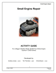
Rev F
6/08
These instructions are for all
models of 120” or 131” Alpha,
Beta Engines (Including Kits)
No.1208-1351
Rev F
6/08
A Division of Thiessen Products, INC
Instruction Sheet For Box 1 120” Or 131”
Engine Assemblies Or Engine Race Kits
The following instructions are for both 120“ or 131” Engine Assemblies” and “Engine Kits”, (top end not
assembled). These instructions will have information not only for assembly of the engine but will have
helpful info in other areas such as: the drive line area, electrical, tuning, oiling, and frame info, etc
Read thoroughly before starting any assembly.
Note: Throughout the following text we will make motor application reference as shown: “A” for Alpha
engines; “B” for Beta engines; and “06 FXD” for 2006 to present DYNA™ and 07 FLH for 2007 to present
FLH’s.
If you ordered and received an assembled engine assembly, we recommend you read all three instruction
booklets to become familiar with your new engine. Note that if your engine assembly does not come
with a carburetor or ignition. You can order carburetor and ignition separately. Call JIMS® sales department for ordering.
JIMS® 120”Or 131” Kit Engine
General Instructions
Check Box Contents:
Verify you have received three (3) of three (3) boxes. After inspecting the exterior of the three boxes for
damage, proceed to open and examine the contents of each box. Make sure there is no damage and
you received the correct version of the JIMS® 120” or 131”” Race Kit. Resist the temptation to open the
sealed plastic bags or the Short Block wrapper. This is to keep the parts as clean as possible. Read red
tag!
Start with Box One:
Verify the engine case color matches with the checked color on the box, or labels. See Fig.1. Use the
checklist on page 9 and confirm you received everything on the list. Close the box.
Box Two:
Verify that the color of the cylinders and heads match with the checked color on the
box label. Use the checklist in box 2 instructions on page 19. Do not unwrap the
heads. Do not unwrap the pistons or rings unless you suspect damage. Close the
box.
Fig.1
Box Three:
See box label. Use the check list to confirm the contents on page 19. Close the Box.
555 Dawson Drive, Camarillo, CA 93012
Phone 805-482-6913 • Fax 805-482-7422
1
No.1208-1351
Rev F
6/08
A Division of Thiessen Products, INC
Instruction Sheet For Box 1 120” Or 131”
Engine Assemblies Or Engine Race Kits
Recommended Ignition
1999-03 “A” and 2000-03 “B” models we recommend the Screamin’ Eagle® adjustable ignition JIMS®
No.1286-1379 or H-D® No.32704-01. On 2004-2006 “A” and “B” models we recommend the
Screamin’ Eagle® Race Tuner Ignition JIMS® No.1286-1376 or H-D® No.32124-04. These are for carburetor models only and these must be ordered separately.
Recommended Carburetor
It is recommended you use a 51mm CV Screamin’ Eagle® carberator JIMS® No.1286-1378, or H-D
No.27926-02. You will need to use 2- JIMS No.1286-1400 or H-D® No.26993-06 flanges and 2No.27035-05 seals. All these parts need to be ordered seperately. See our sales staff for more detailed
information.
Assembly Sequence, all Models:
There is nothing particularly difficult about assembly of the JIMS® 120” or 131” Race Kit engine. With
some differences, assembly is very much the same as if it were a standard TWIN CAM®. However,
because those differences are important, we request you closely follow our assembly instructions. The
JIMS® 120” or 131” Race Kit instructions are arranged in a Step-By-Step sequence. Each step builds
upon and is dependent upon the previous one. If you follow our instructions, Step-By-Step, you shall
assemble your JIMS® 120” or 131” Race Kit engine quickly and correctly.
The details of each step are also important. Please study and follow these step details closely.
NOTE: JIMS® Engines are not equipped for a cam sensor because it is not needed with the recommended ignition module. Disconnect as necessary per bike model shop manual. The pistons and cylinders
of the JIMS® 120” or 131” Race Kit are not interchangeable, front to rear, as they are in the stock TWIN
CAM® engine. The 120’s or 131’s cylinder spigot notches are necessary to get the big bore cylinders
to clear one another. These notches make the front and rear cylinders different from one another. The
rear piston’s skirt notch (intake side) is necessary to clear the front piston when both are at the bottom of their stroke (BDC). See Fig. 2.
All gasket surfaces must be perfectly smooth and clean to properly seal the
special high performance head and base gaskets.
NOTCH
Cleanliness
Your work area must be as clean as possible. From the point of view of
engine building, almost all motorcycle shops and private garages are very
dirty places. Your JIMS® 120” or 131” Race Kit engine is going to have
some of its most highly
REAR
Fig.2
555 Dawson Drive, Camarillo, CA 93012
Phone 805-482-6913 • Fax 805-482-7422
2
No.1208-1351
Rev F
6/08
A Division of Thiessen Products, INC
Instruction Sheet For Box 1 120” Or 131”
Engine Assemblies Or Engine Race Kits
loaded parts separated by an oil film only a millionth of an inch thick. If a particle of dirt larger than the
oil film gets between those parts, they will be damaged. A particle of sandpaper, in the wrong place, may
start a chain of events that can either shorten the wear-life of your new engine or cause it to fail completely. This is not an exaggeration. The greatest single threat to engine life is hard-particle contamination —
“dirt”.
Modern engines can last a very long time. This is partly due to superior materials, more accurate machining and better lubricants. Still, the most important single factor is cleanliness. Truck engines routinely travel 600,000 miles and many reach a million before they are worn out. There are many EVO and TWIN CAM®
Harley® motors having approached or exceeded 200,000 miles of service. None of this could happen if
these engines were dirty inside.
Wash and Cover Everything:
!
Wash your tools. It is not enough to drag a rag through a box-end wrench; wash it
inside as well. Soap, water and scrub brushes are not too extreme. When in doubt clean it. Don’t forget your hands. Pictured at right is our “cleanliness block”. This
block is designed as a reminder to take special care not to introduce dirt or other contamination into your JIMS® 120” or 131” Race Kit. You will find this block located next
to the most dirt sensitive assembly instructions. Wash or cover every surface the
engine parts may contact. Consider using thin plastic ‘drop cloth’ material to cover
the rest of the bench and surrounding area - especially things like bench grinders. In fact do not assemble
your JIMS® 120” or 131” Race Kit in the same room any grinding is performed. Close the door. Turn the
fan off if you can stand to. Do not use air pressure to clean anything. Cleaning with air is like blowing
leaves; it just moves the stuff around. One of the places an air nozzle moves dirt is into your engine. Do
not use it.
Follow all manufacturer’s instructions and heed all warnings specific to each chemical used.
The Boxes:
The exterior of the three boxes are going to be contaminated. Keep them away from your work area. Carry
the individual sealed packages to your bench before opening them. Do not unseal the packages until you
are ready to install or use their contents. Cover with clean plastic or return all parts to their original packaging when you are not working with them.
555 Dawson Drive, Camarillo, CA 93012
Phone 805-482-6913 • Fax 805-482-7422
3
No.1208-1351
Rev F
6/08
A Division of Thiessen Products, INC
Instruction Sheet For Box 1 120” Or 131”
Engine Assemblies Or Engine Race Kits
Box One Engine Race Kit
Installation Instructions
Inspection of parts for box 1
Fig.3 - Box 1 components - See Page 9
For “B” Engine, 06 FXD,
& 07 FL to Pres
Part No. 1486-1835
For “A” Engine, 99-06 FL,
99-05 FXD
Part No. 1286-1346 (Black)
Part No. 1286-1345 (Silver)
Note: Please verify contents of box 1 and complete
inspection of these parts prior to proceeding with
installation as listed on page 9. Please contact
JIMS® Tech Support (805-482-6913) if there are
any issues with the parts enclosed. See Fig.3 and
page 4.
Lower End Assembly Inspection
• Read and remove Red Tag attached to the plastic bag containing the lower end.
• Cut open the protective plastic bag, and with
the help of a friend carefully remove the lower
end from the box and place it into your engine
Fig.3 - Box 1 components - See Pages 9
stand.
• Refer to the manufacturer’s instructions included with your engine stand for proper installation.
• Replace the blue foam rod protectors into cylinder spigot bore (prevents rod from knocking in case).
• Remove masking intended for cleanliness as indicated.
• Check case finish for scratches may have resulted from shipping.
• Cover lower end assembly with the supplied clean clear plastic bag
Note: Touch-up paint is included in box 2 for your convenience. Please see directions for proper application
and curing.
Cylinder Studs
•
•
You will find eight (8) cylinder studs. Two (2) short studs and six (6) long studs.
Verify presence of green loctite 620 for use when installing the cylinder studs.
555 Dawson Drive, Camarillo, CA 93012
Phone 805-482-6913 • Fax 805-482-7422
4
No.1208-1351
Rev F
6/08
A Division of Thiessen Products, INC
Instruction Sheet For Box 1 120” Or 131”
Engine Assemblies Or Engine Race Kits
Oil Filter Mount for Engine “A” 99-06 FL, 99-05 FXD
•
•
•
Remove from package and inspect for debris and imperfections.
Verify the package includes three (3) bolts with washers and one (1) locking flange.
Check that there are two o-rings present.
Tools necessary for box 1 installation: See Fig.4
3/8” drive torque wrench 5-75 ft/lbs
3/8” drive torque wrench 40-200 In/lbs
3/8” drive ratchet
7/8” deep socket
1/2” 12 point socket
7/16” socket
6” caliper
“A” TC Engine Stand, JIMS® No.1022
“B” TC Engine Stand, JIMS® No.902 Small brass punch, JIMS® No.1081
Small brass hammer, JIMS® No.1080
20W - 50 clean H-D® engine oil
Recommended Tools & Supplies
A small tooth brush
Several lint free cloths
A flashlight
One quart 20W-50 H-D® Motor Oil
Alpha Engine
stand shown
use on 99’-06’
JIMS No.1022
The following are required to install the cylinder studs:
The furnished six long and two short studs.
Fig.4 - Tools Required
The furnished Loctite compound 620.
One (1) furnished cylinder dowel pin tool (1/4” x 1/2”)
One (1) furnished Short Head bolt
A solvent to degrease the threads of each stud. Use Loctite primer, ace
tone, denatured alcohol, rubbing alcohol or other non-residue solvent for
this purpose.
Follow all manufacturer’s instructions and heed all warnings specific to
each chemical used.
A small tooth brush (recommended)
A lint-free cloth.
A flashlight (recommended)
555 Dawson Drive, Camarillo, CA 93012
Beta Engine Stand
JIMS No.902 Use on all Betas
Phone 805-482-6913 • Fax 805-482-7422
5
No.1208-1351
Rev F
6/08
A Division of Thiessen Products, INC
Instruction Sheet For Box 1 120” Or 131”
Engine Assemblies Or Engine Race Kits
STEP 1: Preparation
• Inspect the entire surface of the studs for damage. See Fig.5
• Minor scratches are okay in the body of the stud.
• The threaded portion of the studs must not have deformities that stud
would cause binding between the cases or head bolts.
• Set aside and cover.
STEP 2: Inspect the oil filter o-ring sealing surface
• Sealing surface should be smooth and flat.
• If necessary clean thoroughly, set aside and cover. See Fig.8 for Engine “A”
• Inspect both threads for any burrs or dents on oil filter adapter No.14861835.
STEP 3: Base Gasket Surface Preparation
• Clean base gasket surface (case deck) with a clean lint free cloth
and (denatured alcohol/isopropyl alcohol)
• Make certain the cylinder seating surfaces of the cases are
smooth, clean and dry. See Fig. 9.
• Confirm the eight stud holes in the cases are empty, clean and dry.
Fig.5- Clean surfaces
Oil Filter Adapter
for Engine “B”, and
“A” - 06-Pres FXD, &
07-Pres FL No.14861835
Fig.6 - Oil filter unit
STEP 4: Stud Installation: See Fig.7 & Fig. 8.
Note: These studs are not designed to be an interference fit, however there
may be slight drag on some studs as they are installed into the case.
• Each stud is installed with two (2) small drops of Loctite 620 on the
first four (4) threads, and (2) small drops in each cylinder stud case
hole.
Fig.7- 3/8” Head bolt end
Fig.8- 7/16” Case stud end
Note: Dirt is an engine’s worst enemy!
555 Dawson Drive, Camarillo, CA 93012
Phone 805-482-6913 • Fax 805-482-7422
6
No.1208-1351
Rev F
6/08
A Division of Thiessen Products, INC
Instruction Sheet For Box 1 120” Or 131”
Engine Assemblies Or Engine Race Kits
IMPORTANT NOTE: Use a head bolt and the furnished cylinder dowel
pin to drive the studs.
CAUTION: Loctite 620 sets extremely quick, do not stop until the
stud has been installed to the correct height.
• Apply a small amount of moly lube, about 1/16” diameter drop, to the 1/4”
dowel pin, this will help stop the pin from falling out when removing the head
bolt from the stud.
• Install the lubed dowel pin into a short head bolt.
• Set the longer studs out of easy reach while you install the short ones.
• Screw a short stud into the head bolt until stopped by the dowel pin.
• Use this assembly to drive the short studs into the right (cam) side of the engine
case. See Fig.9.
• Apply one (1) small drop of Loctite® 620 to the first four (4) threads of one side
of the 7/16” case stud threads and then apply one more drop, 180 degrees, on
the other side of the stud’s first four (4) threads. See Fig.10.
• Apply one (1) small drop of Loctite® 620 to the threads of the center stud holes
on the right (cam) side of the case. Then apply a second drop, 180 degrees, on
the other side of the same case stud hole. See Fig.11.
• Drive both short studs, as pictured, until the distance measured with your
calipers between the case and the bottom of the head bolt is 4.650”+/- .030”
above the case deck (gasket surface of the short block). See Fig.12.
• Verify the top of each stud without the head bolt attached should protrude
5.250” +/- .030” from the case deck. See Fig.13.
• Repeat procedure for the remaining 6 long studs.
• Remove any visible Loctite with a clean cloth from gasket surface.
Fig.9- Install short studs here
Fig.10 - Apply supplied thread
lock
Fig.11- Apply supplied thread
lock
Fig.13- Measure stud height
555 Dawson Drive, Camarillo, CA 93012
Fig.12 - Measure stud height
Phone 805-482-6913 • Fax 805-482-7422
7
No.1208-1351
Rev F
6/08
A Division of Thiessen Products, INC
Instruction Sheet For Box 1 120” Or 131”
Engine Assemblies Or Engine Race Kits
STEP 5: Oil filter mount installation
•
•
•
Remove stickers located over 2 holes located where filter mounts to case.
Refer to the instructions included with your oil filter mount kit for Engine “A” 99-05 FXD, and
99-06 FLH.
For Engine “B” and 06-Pres.FXD remove 1-7/8 sticker from case where filter mounts. Thread in
adapter with lock patch into case with a 7/8” hex socket, torque to 120-168 inch-lbs.
STEP 6: Sprocket shaft spacer installation
•
•
•
•
•
•
•
•
•
Inspect the engine sprocket shaft, seal and bearing cavities for any
packaging debris before continuing. See Fig. 14
Locate spacer specific to your application
Dyna Models 24038-99A “A” for 1999 to 2005
Softail® Models 24038-99A “B” for 2000
FL Models 24008-99A “A” & 2006 Dyna™ Models
Softail® Models 24039-01A “B” for 2001-2006
Inspect spacer for nicks and dents.
Lightly coat outside diameter of sprocket shaft spacer and the inside
of the sprocket shaft seal with clean 20w-50 H-D® motor oil.
Slide sprocket shaft spacer onto sprocket shaft, (see illustration)
until it is seated on the sprocket shaft bearing. See Fig.15. If you purchased a complete engine assy, go to page 11 step 11 of the Box 3
Instructions #1208-1353.
Fig.14- Inspect
You now have a completed “Short Block.”
Cover and seal this assembly with the supplied clear plastic bags. When ready
proceed to Box 2 installation instructions.
Fig.15- Install spacer
NOTES
555 Dawson Drive, Camarillo, CA 93012
Phone 805-482-6913 • Fax 805-482-7422
8
No.1208-1351
Rev F
6/08
A Division of Thiessen Products, INC
Instruction Sheet For Box 1 120” Or 131”
Engine Assemblies Or Engine Race Kits
BOX 1 Materials Check-Off Sheet
Part No.
No.
Part
®
H-D
H-D® No.
No.
Description
Description
Qty.
Qty.
1290-1309
120” Lower End Assembly (Black) “A” 1999-Pres. FL, 99-05 FXD
1
1290-1315
120” Lower End Assembly (Sliver) “A” 1999-Pres. FL, 99-05 FXD
1
1390-1309
131” Lower End Assembly (Black) “A” 1999-Pres. FL, 99-05 FXD
1
1390-1315
131” Lower End Assembly (Sliver) “A” 1999-Pres. FL, 99-05 FXD
1
1490-1309
120” Lower End Assembly (Black) “B” 2000-2006 FXST
1
1490-1315
120” Lower End Assembly (Sliver) “B” 2000-2006 FXST
1
1690-1309
120” Lower End Assembly (Black) 06-Pres. FXD, 07 to Pres. FLH
1
1690-1315
120” Lower End Assembly (Sliver) 06-Pres. FXD, 07 to Pres. FLH
1
1708-1309
131” Lower End Assembly (Black) 06-Pres. FXD, 07 to Pres. FLH
1
1708-1315
131” Lower End Assembly (Sliver) 06-Pres. FXD, 07 to Pres. FLH
1
1286-1319 24038-99A
Spacer, Sprocket Shaft “A” 99-05 FXD also “B” 2000 FXST.
1
1486-1834 24039-99A
Spacer, Sprocket shaft “B”, 2001-2006 FXST
1
1286-1320 24008-99A
Spacer, Sprocket Shaft “A” 99-Pres. FLH,06-Pres.FXD
1
1286-1346 26261-99
Oil Filler Mount Kit (Black) “A” 99-07 FL, 99-05 FXD
1
1286-1345 26274-99
Oil Filler Mount Kit (Silver) “A” 99-06 FL, 99-05 FXD
1
1486-1835 26352-95A
Adapter, Oil Filler “B” 2000-Pres. FXST, 06-Pres.FXD, 07-Pres.FL
1
1286-1360
Cylinder Stud (Long) “A”& “B”
6
1286-1361
Cylinder Stud (Short) “A”,&“B”
2
1286-1362
Retaining Compound #.620 .02oz “A”&“B”
2
1286-1387
Stud Installer Tool “A”,& “B”
1
1286-1395
Bag. 24X24 (To Cover Engine”B”)
1
1286-1394
Zip Tie, Motor Bagging ,“A”,&“B”
1
1208-1302
Red Tag, Shipping “A”, & “B”
1
1286-1330
Molly Lube, Package “A”,& “B”
1
1286-1331 16478-85A
Screw, Internal Thread, 3-3/16” “A”,& “B”
4
1286-1332 16480-92
Screw, Internal Thread, 1-7/8”,“A”,& “B”
4
1208-1304
Warranty Card “A”,& “B”
1
1208-1351
Instruction Sheet “A”,& “B”
1
555 Dawson Drive, Camarillo, CA 93012
Phone 805-482-6913 • Fax 805-482-7422
9