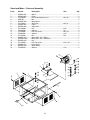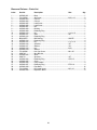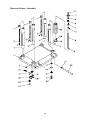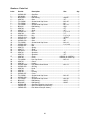
1
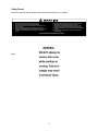
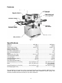
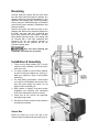
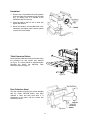
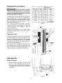
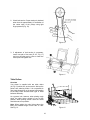
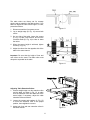
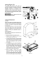
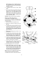
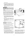
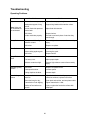
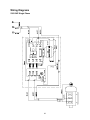
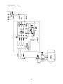
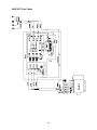
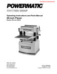
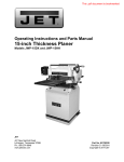
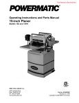
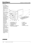
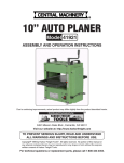
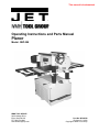
This manual is bookmarked
Operating Instructions and Parts Manual
Planer
Model: JWP-208
WMH TOOL GROUP
2420 Vantage Drive
Elgin, Illinois 60123
Ph.: 800-274-6848
www.wmhtoolgroup.com
Part No. M-708528
Revision G1 06/06
Copyright © WMH Tool Group
Warranty and Service
WMH Tool Group, Inc., warrants every product it sells. If one of our tools needs service or repair, one of our
Authorized Service Centers located throughout the United States can give you quick service. In most cases, any of
these WMH Tool Group Authorized Service Centers can authorize warranty repair, assist you in obtaining parts, or
perform routine maintenance and major repair on your JET® tools. For the name of an Authorized Service Center in
your area call 1-800-274-6848.
MORE INFORMATION
WMH Tool Group is consistently adding new products to the line. For complete, up-to-date product information, check
with your local WMH Tool Group distributor, or visit jettools.com.
WARRANTY
JET products carry a limited warranty which varies in duration based upon the product. (MW = Metalworking, WW =
Woodworking)
WHAT IS COVERED?
This warranty covers any defects in workmanship or materials subject to the exceptions stated below. Cutting tools,
abrasives and other consumables are excluded from warranty coverage.
WHO IS COVERED?
This warranty covers only the initial purchaser of the product.
WHAT IS THE PERIOD OF COVERAGE?
The general JET warranty lasts for the time period specified in the product literature of each product.
WHAT IS NOT COVERED?
Five Year Warranties do not cover woodworking (WW) products used for commercial, industrial or educational
purposes. Woodworking products with Five Year Warranties that are used for commercial, industrial or education
purposes revert to a One Year Warranty. This warranty does not cover defects due directly or indirectly to misuse,
abuse, negligence or accidents, normal wear-and-tear, improper repair or alterations, or lack of maintenance.
HOW TO GET SERVICE
The product or part must be returned for examination, postage prepaid, to a location designated by us. For the name
of the location nearest you, please call 1-800-274-6848.
You must provide proof of initial purchase date and an explanation of the complaint must accompany the
merchandise. If our inspection discloses a defect, we will repair or replace the product, or refund the purchase price,
at our option.
We will return the repaired product or replacement at our expense unless it is determined by us that there is no
defect, or that the defect resulted from causes not within the scope of our warranty in which case we will, at your
direction, dispose of or return the product. In the event you choose to have the product returned, you will be
responsible for the shipping and handling costs of the return.
HOW STATE LAW APPLIES
This warranty gives you specific legal rights; you may also have other rights which vary from state to state.
LIMITATIONS ON THIS WARRANTY
WMH TOOL GROUP LIMITS ALL IMPLIED WARRANTIES TO THE PERIOD OF THE LIMITED WARRANTY FOR
EACH PRODUCT. EXCEPT AS STATED HEREIN, ANY IMPLIED WARRANTIES OR MERCHANTABILITY AND
FITNESS ARE EXCLUDED. SOME STATES DO NOT ALLOW LIMITATIONS ON HOW LONG THE IMPLIED
WARRANTY LASTS, SO THE ABOVE LIMITATION MAY NOT APPLY TO YOU.
WMH TOOL GROUP SHALL IN NO EVENT BE LIABLE FOR DEATH, INJURIES TO PERSONS OR PROPERTY,
OR FOR INCIDENTAL, CONTINGENT, SPECIAL, OR CONSEQUENTIAL DAMAGES ARISING FROM THE USE
OF OUR PRODUCTS. SOME STATES DO NOT ALLOW THE EXCLUSION OR LIMITATION OF INCIDENTAL OR
CONSEQUENTIAL DAMAGES, SO THE ABOVE LIMITATION OR EXCLUSION MAY NOT APPLY TO YOU.
WMH Tool Group sells through distributors only. The specifications in WMH catalogs are given as general information
and are not binding. Members of WMH Tool Group reserve the right to effect at any time, without prior notice, those
alterations to parts, fittings, and accessory equipment which they may deem necessary for any reason whatsoever.
JET® branded products are not sold in Canada by WMH Tool Group.
2
Table of Contents
Table of Contents.......................................................................................................................................... 3
Warnings ....................................................................................................................................................... 4
Features ........................................................................................................................................................ 6
Specifications ................................................................................................................................................ 6
Receiving....................................................................................................................................................... 7
Installation & Assembly ................................................................................................................................. 7
Starter Box................................................................................................................................................. 7
Handwheel................................................................................................................................................. 8
Table Extension Rollers............................................................................................................................. 8
Dust Collection Hood................................................................................................................................. 8
Electrical Connections................................................................................................................................... 9
Extension Cords ........................................................................................................................................ 9
Adjustments .................................................................................................................................................. 9
Belt and Pulleys......................................................................................................................................... 9
Table Rollers ........................................................................................................................................... 10
Overview .............................................................................................................................................. 10
Adjusting Table Extension Rollers ....................................................................................................... 11
Adjusting Depth of Cut............................................................................................................................. 12
Cutterhead Adjustment............................................................................................................................ 12
Overview .............................................................................................................................................. 12
Knife Adjustment.................................................................................................................................. 12
Replacing & Resetting Knives ................................................................................................................. 13
Adjusting Work Table Parallel to Cutterhead .......................................................................................... 14
Anti-Kickback Fingers.............................................................................................................................. 15
Adjusting Infeed & Outfeed Roller Spring Tension.................................................................................. 15
Height of Infeed Roller, Chipbreaker, Pressure Bar & Outfeed Roller .................................................... 16
Feed Speed Control ................................................................................................................................ 17
Changing Accessories for Lowest Feed Speed ...................................................................................... 17
Return Rollers.......................................................................................................................................... 17
Maintenance................................................................................................................................................ 18
Lubrication................................................................................................................................................... 18
Troubleshooting .......................................................................................................................................... 20
Operating Problems................................................................................................................................. 20
Mechanical and Electrical Problems ....................................................................................................... 21
Optional Accessories .................................................................................................................................. 22
Ordering Replacement Parts....................................................................................................................... 22
Parts ............................................................................................................................................................ 22
Head Assembly – Parts List .................................................................................................................... 22
Head Assembly – Exploded View ........................................................................................................... 25
Table and Roller – Parts and Assembly .................................................................................................. 26
Stand and Motor – Parts and Assembly.................................................................................................. 27
Base and Column – Parts List................................................................................................................. 28
Base and Column – Assembly ................................................................................................................ 29
Gearbox – Parts List................................................................................................................................ 30
Gearbox – Assembly ............................................................................................................................... 31
Wiring Diagrams.......................................................................................................................................... 32
230V 3HP Single Phase .......................................................................................................................... 32
230V 5HP Three Phase .......................................................................................................................... 33
460V 5HP Three Phase .......................................................................................................................... 34
3
Warnings
Read the manual. Always read the owner’s manual carefully before attempting to use the machine.
Know the limitations and hazards associated with the use of this planer.
Installation. If mounting machine to the floor, use high quality anchor bolts through the mounting holes
on the base. If using a mobile base, be sure to lock the wheels.
Eye protection. Always wear approved safety goggles, glasses, or a face shield when operating this
machine. NOTE: Common eyeglasses are only impact resistant, they are not safety glasses. Also use
face or dust mask if the cutting operation is dusty.
Dress code. Do not wear loose clothing, neckties, jewelry, or gloves that can get caught in moving parts.
Confine long hair. Keep sleeves above the elbow.
Placement. Place machine so that potential kickback area is not in line with aisles, doorways, wash
stations or other work areas. Do not use machine in a damp or wet location, or expose to rain. Keep work
area well lighted.
Electrical grounding. Your machine must be electrically grounded. If a cord and plug are used, make
certain the grounding lug connects to a suitable ground. Follow the grounding procedure indicated by the
National Electrical Code.
Guards. Be sure machine guards are in place and in good working order. Do not operate while gear
cover is open. If a guard must be removed for adjustments or maintenance, it should be reinstalled
immediately upon completion of the procedure and before operating the machine.
Housekeeping. Before turning on machine, remove all extra equipment such as keys, wrenches, scrap,
stock, and cleaning rags from the machine. Keep the area around machine clean and free of scrap
material and sawdust to minimize the danger of slipping.
Power off. Make sure the machine is either unplugged or electrically disconnected and locked out when
performing maintenance or service work. Also, make sure switch is in OFF position before plugging in
power cord. Never leave the machine running unattended. Do not leave machine until it comes to a
complete stop.
Cutterhead. Keep knives sharp and free of all rust and pitch. Make sure gib screws are tightened
securely.
Work piece. Check material for loose knots, nails and other defects that can damage knives and pose a
safety hazard for the operator.
Keep hands away from feed rollers and cutterhead while operating.
Use the proper extension cord. Make sure your extension cord is in good condition. When using an
extension cord, be sure to use one heavy enough to carry the current your product will draw. An
undersize cord will cause a drop in line voltage resulting in loss of power and overheating. For runs up to
25 feet, use an 18 AWG or larger gauge cord.
Do not operate this machine while under the influence of drugs, alcohol or any medication.
If you are not thoroughly familiar with the operation of wood planers, obtain advice from your supervisor,
instructor or other qualified person.
Health hazards. Some dust created by power sanding, sawing, grinding, drilling and other construction
activities contains chemicals known to cause cancer, birth defects or other reproductive harm. Some
examples of these chemicals are:
x Lead from lead-based paint.
x Crystalline silica from bricks and cement and other masonry products.
x Arsenic and chromium from chemically-treated lumber.
Your risk from these exposures varies, depending on how often you do this type of work. To reduce your
exposure to these chemicals, work in a well-ventilated area, and work with approved safety equipment,
such as those dust masks that are specifically designed to filter out microscopic particles.
4
Safety Decals
Familiarize yourself with the location and content of these decals on your planer.
!
1.
2.
3.
4.
5.
6.
Read instruction manual before operating machine.
Do not operate without all guards properly installed.
Remove or fasten loose articles of clothing such as neckties, etc.
Contain long hair.
Remove jewelry such as finger rings, watches, bracelets, etc.
Use approved safety glasses and/or face shield to protect eyes, and
use other personal safety equipment as required. Do not wear
gloves.
7.
8.
9.
Disconnect machine from power source before making any
adjustments or cleaning chips away from machine.
Keep the floor around machine clean and free from scraps,
sawdust, oil and grease to minimize the danger of slipping.
Do not operate this machine while under the influence of alcohol
or drugs.
Failure to comply with these warnings may result in serious
personal injury.
DO NOT REMOVE OR OBSCURE THIS LABEL
Fig. 1
5
Features
Fig. 2
Specifications
Model No. ........................................................................... JWP-208-1........................................ JWP-208-3
Stock No................................................................................... 708528.............................................. 708584
Table Area (D x W/in.)........................................................ 25-3/4 x 20........................................ 25-3/4 x 20
Maximum Planing (W/in.) ................................................................. 20...................................................... 20
Maximum Planing (T/in.) .................................................................... 6........................................................ 6
Full Width Cutting Depth (in.) ........................................................ 3/32................................................... 3/32
Minimum Planing Depth (in.)........................................................ 6-3/4..................................................6-3/4
Knives................................................................................................. 4........................................................ 4
Blade Size (L x W x T/in.)...................................................20 x 1 x 1/8....................................... 20 x 1 x 1/8
Cutterhead Speed (RPM)............................................................ 5,000................................................. 5,000
Cuts per Minute......................................................................... 20,000............................................... 20,000
Cutterhead Diameter (dia/in.)..................................................... 3-3/16................................................3-3/16
Feed Rate (FPM) ..................................................................... 24 & 31..............................................24 & 31
Dust Chute Diameter (dia/in.)............................................................. 5........................................................ 5
Overall Dimensions (L x W x H/in.) ...................... 26 x 36-5/8 x 41-3/8.......................... 26 x 36-5/8 x 41-3/8
Motor ....................................................................3HP, 1Ph,230V only......................... 5HP, 3Ph, 230/460V
................... (prewired 230V)
Overall Dimensions (L x W x H/in.) ...................... 26 x 36-5/8 x 41-3/8.......................... 26 x 36-5/8 x 41-3/8
Net Weight (approx. lbs.) ............................................................... 640.................................................... 640
The specifications in this manual are given as general information and are not binding. WMH Tool Group
reserves the right to effect, at any time and without prior notice, alterations to parts, fittings, and
accessory equipment deemed necessary for any reason whatsoever.
6
Receiving
Carefully unpack the planer and any loose items
from the wood crate and inspect for damage. Any
damage should be reported immediately to your
distributor and shipping agent. Before proceeding
further, read your manual thoroughly to familiarize
yourself with proper assembly, maintenance and
safety procedures.
Remove the screws that hold the planer to the
shipping skid. Remove the protective coating from
the table, bed rolls, feed rolls, cutterhead and
loose items packed with the machine, including
lifting handles and motor pulley. This coating may
be removed with a soft cloth moistened with
Kerosene. Do not use acetone, gasoline or
lacquer thinner for this purpose. Do not use
solvents on plastic parts.
Use care when cleaning the
cutterhead, the knives are very sharp.
Installation & Assembly
1. There are four lifting handles (Fig. 3) on the
machine. Pull the handles out for use, push in
when not in use.
2. If a sling or forklift is used to lift the machine,
be sure to lift by the handles only. See Fig. 3.
Make sure machine is kept in level position
while lifting.
3. For best planing performance, locate planer
on a solid, level foundation and anchor to the
floor with good quality lag screws. Do not
tighten screws completely yet.
Figure 3
4. With machine in position, test table surface
lengthwise and crosswise with machinist’s
level. Place metal shims under low corners.
5. Check that all four corners are supported,
then tighten lag screws.
6. Re-test level of table surface in both directions
and adjust if necessary.
Starter Box
Mount the starter box at the left side of the
machine with two socket head cap screws (Fig. 4).
Figure 4
7
Handwheel
1. Remove the nut and washer from the gearbox
shaft, and place the handwheel onto the shaft
(Fig. 5), making sure it is oriented so the
handwheel slips over the key.
2. Place flat washer and hex nut on shaft and
tighten with wrench.
3. Mount the handle in the threaded hole in the
handwheel, and tighten with a wrench placed
over the flat on the handle.
Figure 5
Table Extension Rollers
Mount the table extension rollers to the table using
the provided hex cap screws and washers
(A, Fig. 6). The rollers should be adjusted before
operating the planer; see Adjusting Table
Extension Rollers on page 11.
Figure 6
Dust Collection Hood
The dust collection hood (Fig. 6a) comes standard
with the model JWP-208 planer, and helps
maintain a clean and safe work area. It is
assembled to the planer with the screws and
washers as shown.
Figure 6a
8
Electrical Connections
Electrical connections must be
made by a qualified electrician in compliance
with all relevant codes. The machine must be
properly grounded to help prevent electrical
shock and possible fatal injury.
A power plug is not provided with the 208 planer.
You may either connect one or "hard-wire" the
machine directly to your electrical panel provided
there is a disconnect near the machine. Consult
the wiring diagrams on pages 32-33 for further
clarification of wiring setup.
Figure 7
This machine must be grounded. Grounding
provides a path of least resistance to help divert
current away from the operator in case of
electrical malfunction.
Make sure the voltage of your power supply
matches the specifications on the motor plate of
the machine.
Extension Cords
The use of an extension cord is not recommended
for this machine, but if one is necessary make
sure the cord rating is suitable for the amperage
listed on the machine's motor plate. An undersize
cord will cause a drop in line voltage resulting in
loss of power and overheating.
The chart in Figure 7 shows the correct size cord
to use based on cord length and motor plate amp
rating. If in doubt, use the next heavier gauge. The
smaller the gauge number the heavier the cord.
Figure 8
Adjustments
Belt and Pulleys
1. Using a straight edge, align the motor pulley
(A, Fig. 8 ) and cutterhead pulley (B, Fig. 8).
The motor plate can be moved for alignment
by loosening the set screws (C, Fig. 9) in the
motor plate.
Figure 9
9
2. Check belt tension. Proper tension is obtained
when there is approximately 1/4” deflection of
the center span of the pulleys using light
finger pressure (Fig. 10).
Figure 10
3. If adjustment of belt tension is necessary,
loosen one pair of hex nuts (E & F, Fig. 11)
and turn the other pair to raise or lower the
motor plate. Re-tighten nuts.
Figure 11
Table Rollers
Overview
Your planer is supplied with two table rollers
(A, Fig. 12) which turn as the stock is fed into the
planer, thus reducing friction. It is not possible to
give exact dimensions on the proper height setting
of the table rollers because each type of wood
behaves differently.
As a general rule, however, when planing rough
stock, the table rollers should be set at high
position. When planing smooth stock the rollers
should be set at low position.
Note: When raising the roller higher above the
table, the available range is from .003” to .006”
See Fig. 13.
Figure 12
10
The table rollers are factory set for average
planing and are parallel to the table surface. If you
desire to adjust the table rollers higher or lower,
proceed as follows:
Figure 13
1. Disconnect machine from power source.
2. Lay a straight edge (B, Fig. 14) across both
rollers.
3. On one side of the table, loosen the screws
(C, Fig. 14) with a hex wrench, and turn the
eccentric shafts (D, Fig. 14) to raise or lower
the rollers.
4. When the proper height is achieved, tighten
screws (C, Fig. 14).
5. Adjust the rollers from the opposite side of the
table in the same manner.
Important: Be sure that the height of front and
rear rollers are the same. The table rollers must
always be set parallel to the table.
Figure 14
Adjusting Table Extension Rollers
1. Place a straight edge over the extension roller
and the table, as shown in Fig. 15, to make
sure the extension roller and table are at the
same height. If necessary, adjust the table
extension rollers as follows:
2. Loosen the screws and washers (A, Fig. 15)
to move the extension roller to the proper
position, then retighten the screws.
3. Adjust both front and rear extension rollers in
the same manner.
Figure 15
11
Adjusting Depth of Cut
The cutting depth scale (A, Fig. 16) is a
combination inch/metric scale with a cutting range
from 0 to 8” (204mm). The distance of upward or
downward movement is controlled by the
handwheel (B, Fig. 16). One revolution of the
handwheel is .059” (1.5mm). Before moving the
table up or down, loosen the lock nuts (C, Fig. 16).
After obtaining the proper table position, tighten
the lock nuts (C, Fig. 16).
Always tighten the lock nuts
before operating the planer.
Figure 16
Cutterhead Adjustment
Overview
Although your planer was carefully adjusted at the
factory, it should be checked before being put into
operation. Any inaccuracies due to rough handling
in transit can easily be corrected by following
these directions.
To check the adjustments you will need a straight
edge, feeler gauge, and a home made gauge
block made of hardwood. This gauge block can be
made by following the dimensions shown in
Figure 17.
Knife Adjustment
When checking or adjusting the cutterhead knives,
proceed as follows:
1. Disconnect machine from power source.
2. Remove the six screws (A, Fig. 18) and
remove upper cover (B, Fig. 18).
Figure 17
3. To check and adjust knives, use the provided
knife gauge (Fig. 19 & 20) and check all four
knives. Knives should just contact the bottom
of the center protrusion (D, Fig. 19) of the
knife gauge.
4. If an adjustment to one or more of the knives
is necessary, slightly loosen the knife gib
(E, Fig. 19) by turning the six locking screws
(F, Fig. 19) into the gib. Turn the screws just
enough to relieve stress in the cutterhead
without disturbing the setting of the knives. Do
this for all four knives at the same time.
5. With the gauge in place over a knife
(G, Fig. 19) continue to loosen the locking
screws (F, Fig. 19) until the springs
(H, Fig. 19) begin raising the knife. When knife
comes into contact with the center protrusion
(D, Fig. 19) of the gauge, snug up the gib by
Figure 18
12
lightly backing out the six locking screws (F,
Fig. 19) against the slot. NOTE: At this time,
only tighten the knife in the slot just enough to
hold knife in position.
6. If additional knives must be reset, repeat
step 5.
7. After all four knives are set with screws just
snug, back out and tighten the six locking
screws (F, Fig. 19 & 20), against the slot
starting with the end screws first, then the
center screws, until the knife is securely held
in the cutterhead. Tighten remaining three
knives in the same manner.
Important: Double check all screws for tightness.
Replacing & Resetting Knives
If the knives are removed for sharpening, care
must be exercise in replacing and resetting them.
Proceed as follows:
1. Disconnect machine from power source.
2. Remove six screws and upper cover (see
Fig. 18).
3. To remove knife, loosen the gib (E, Fig. 19) by
turning the six locking screws (F, Fig. 19) into
the gib. Remove gib (E, Fig. 19), knife (G, Fig.
16) and springs (H, Fig. 19). NOTE: The inner
two springs may pop out when the knife and
gib are removed.
Figure 19
4. Remove the remaining three knives in the
same manner.
5. Thoroughly clean the knife slots, gibs, springs
and locking screws. Check the locking screws;
if the threads appear worn or stripped or if the
heads are becoming rounded, replace them.
6. Inspect the cutting edge of the knives for nicks
or wire edge. Hone the knives slightly using a
stone, or if the knives are to be sharpened,
maintain a cutting angle of 35 degrees.
7. Insert springs, knives and gib into slot of
cutterhead. Back out locking screws just
enough to hold the knife in the cutterhead.
Figure 20
8. Place knife gauge (C, Fig. 19) over knife.
9. While holding down on the knife gauge,
loosen all six locking screws (F) by turning
them into the gib (E) until cutting edge of knife
comes into contact with the protrusion (D) of
the gauge. Snug up the gib by slightly backing
out the six locking screws against the slot.
Note: At this time, only tighten the knife into the
slot just enough to hold the knife in position.
10. Replace and reset the other three knives in
13
the same manner.
11. After all four knives are set with the screws
just snug, back out and tighten the six screws
(F) against the slot starting with the end
screws first and then the center screws until
the knife is securely held in the cutterhead.
Tighten the remaining three knives in the
same manner.
After replacing and checking
knives, CHECK AGAIN carefully. Make certain
the direction of knives is correct and all
twenty-four locking screws are tightened
securely.
Checking Work Table Parallel to Cutterhead
The work table is set parallel to the cutterhead at
the factory and no further adjustment should be
needed. If your machine is planing a taper, first
check to see if the knives are set properly in the
cutterhead. Then check to see if the work table is
set parallel to the cutterhead. Proceed as follows:
1. Disconnect machine from power source.
Figure 21
2. Place the gauge block (A, Fig. 21) on the work
table directly under front edge of head casting
(B, Fig. 21). Make slight contact by gently
raising table.
3. Move the gauge block to opposite end of
working table. NOTE: Distance from the
working table to edge of the head casting
should be the same.
4. Check the back of the work table in the same
manner.
Adjusting Work Table Parallel to
Cutterhead
If the work table is not parallel to the cutterhead,
perform the adjustment procedure as follows:
1. Disconnect the machine from power source.
2. Tilt planer on its side to expose underside of
base, as shown in Fig. 22.
3. Remove bolt (A, Fig. 22) and loosen bolt (B,
Fig. 22) which will allow you to move the idler
sprocket assembly (C, Fig. 22) far enough to
release tension on the chain.
Figure 22
4. Remove chain from the particular sprocket on
corner of base that must be adjusted.
5. Turn the sprocket by hand to bring that corner
into adjustment with the other three corners.
NOTE: Turning sprocket clockwise will
increase the distance between the working
table and headcasting; counter-clockwise will
decrease the distance. This adjustment is very
sensitive and it should not be necessary to turn
the sprocket more than one or two teeth.
6. When adjustments are correct, replace chain
around corner sprocket, slide sprocket (C, Fig.
22) back to re-tension chain, tighten bolt (B, Fig.
22) and replace and tighten bolt (A, Fig. 22).
14
Know the Transmitting Rollers of Your Planer
A – Anti-Kickback Fingers
B – Infeed Roller
C – Chipbreaker
D – Cutterhead
D – Pressure Bar
E – Outfeed Roller
The infeed roller (B, Fig. 23) and outfeed roller
(F, Fig. 23) are those parts of your planer that feed
the stock while it is being planed. The infeed and
outfeed rollers are under spring tension and this
tension must be sufficient to feed the stock
uniformly through the planer without slipping but
should not be so tight that it causes damage to the
board. The tension should be equal at both ends
of each roller.
Figure 23
Anti-Kickback Fingers
The anti-kickback fingers (A, Fig 23) help prevent
kickback of stock. They operate by gravity and it is
necessary to inspect them occasionally to make
sure they are free of gum and pitch, so that they
move independently and operate correctly.
Adjusting Infeed & Outfeed Roller
Spring Tension
To adjust the spring tension of the infeed and
outfeed rollers, turn screws (G & H, Fig. 24) with a
hex wrench. Turn screws on opposite end of
infeed/outfeed rollers in the same manner.
Figure 24
15
Figure 25
Height of Infeed Roller, Chipbreaker,
Pressure Bar & Outfeed Roller
The infeed roller, chipbreaker, pressure bar and
outfeed roller are adjusted at the factory. The
infeed roller and the chipbreaker should be set
at 0.004” (0.1mm) below the cutting circle; and
the outfeed roller should be set at 0.02” (0.5mm)
below the cutting circle. See Fig. 25.
If an adjustment to the infeed roller, chipbreaker,
pressure bar or outfeed roller is necessary, use
the following steps as an example of procedure.
Figure 26
To check and adjust the outfeed roller below the
cutting circle, proceed as follows:
1.
2.
3.
4.
Disconnect machine from power source.
Make sure the knives are adjusted properly
as previously explained under “Checking &
Adjusting of Knives.”
Place the gauge block (J, Fig. 26) on the
table directly underneath the cutterhead (D,
Fig. 26). Using a 0.02” (0.5mm) feeler
gauge (K, Fig. 26) placed on top of the
gauge block, raise the working table until
the knife just touches the feeler gauge
when the knife is at its lowest point. Do not
move the working table any further until the
outfeed roller is adjusted.
5.
Move the gauge block (J, Fig. 27) under
one end of the outfeed roller (F, Fig. 27).
The bottom of the outfeed roller should just
touch the top of the gauge block. If an
adjustment to the outfeed roller is
necessary, loosen the lock nut (L, Fig 27)
and turn screw (M, Fig. 27) until the outfeed
roller just touches the gauge block. Then
tighten lock nut (L, Fig. 27).
Check and adjust opposite end of the
outfeed roller in the same manner.
Figure 27
16
Feed Speed Control
Your machine is equipped with a spiral, serrated
infeed roller and a solid outfeed roller. When the
feed rollers are engaged, they turn to feed the
stock. The feed rollers slow automatically when
the machine is under heavy load for best planing
in all conditions. The feed rollers are driven by
chains (A, Fig. 28) and sprockets (B, Fig. 28)
which take power directly from the cutterhead
through the oil bath gear box (C, Fig. 28).
The gear box has two feed speeds. These are
set by pulling out or pushing in the shift lever (D,
Fig. 28) while the machine is running. The feed
speed range is shown in Fig. 29.
Figure 28
Changing Accessories for Lowest
Feed Speed
The lowest feed speed for your planer (16.2 fpm
& 20.7 fpm) can be obtained by replacing the
lower (gear shaft) sprocket and the chain. See
Fig. 29. To change the sprocket and the chain
on your machine, proceed as follows:
1. Disconnect machine from power source.
2. Remove the three hex cap screws and
washers (E, Fig. 28).
3. Remove the three sprockets (B, Fig. 28)
from the infeed roller, outfeed roller and the
gear shaft at the same time.
4. When the sprockets (B, Fig. 28) are
removed, replace the lower sprocket which
will be assembled on the gear shaft.
5. Assemble the three sprockets and chains to
the shafts, and tighten the hex cap screws
(E, Fig. 28).
Figure 29
Return Rollers
The two return rollers on the top of the machine
serve as a convenient rest for stock. They save
time and motion for the operator as the stock is
returned to the infeed side.
17
Maintenance
Lubrication
Periodic or regular inspections are required to
ensure that the machine is in proper adjustment,
that all screws are tight, that belts are in good
condition, that dust has not accumulated in the
electrical enclosures, and that there are no worn
or loose electrical connections.
The bearings on the cutterhead are factory
lubricated and sealed for life – no lubrication
required.
The lubricant in the gearbox must be replaced
every 2,500 hours. Multi-purpose gearbox
lubricant will be suitable.
Buildup of sawdust and other debris can cause
your machine to plane inaccurately. Periodic
cleaning is not only recommended but mandatory
for accurate planing.
To replace the gearbox lubricant:
Remove the drain plug (A, Fig. 30), and filler cap
(B, Fig. 30). Drain dirty oil thoroughly.
Close-fitting parts, such as the cutterhead slot
and gibs, should be cleaned with a cloth or brush
and non-flammable solvent, and freed from
clinging foreign matter.
Tighten the drain plug (A, Fig. 30).
Fill with clean lubricant through hole (B, Fig.
30).
Tighten filler cap (B, Fig. 30).
Remove resin and other accumulations from feed
rollers and table with a soft rag and nonflammable solvent.
Periodically check all the chains for proper
tension and adjust accordingly if required.
Tip: If a foreign object nicks the knives, instead of
throwing them away or trying to grind out the
deep nick, simply stagger the knives in the head,
moving one knife no more than 1/4" to the right
and another knife no more than 1/4" to the left.
The nick should no longer be noticeable.
The table should be kept clean and free of rust.
Some users prefer a paste wax coating. Another
option is talcum powder applied with a
blackboard eraser rubbed in vigorously once a
week; this will fill casting pores and form a
moisture barrier. This method provides a table
top that is slick and allows rust rings to be easily
wiped from the surface. Important also is the fact
that talcum powder will not stain wood or mar
finishes as wax pickup does.
[The item numbers on this chart are referenced with the accompanying illustrations.]
No.
Position
Interval
Suitable Types of Lubricant
Fig. No.
1
Drive Chain
Frequently
Grease
30
2
Gear Box
When operated more
than 2,500 hours
HD-100, Mobil Gear 627, Shell
Omala 100, ESSO Spartan EP-100
30
3
Return Rollers
Frequently
SAE-30
32
4
Worm Gear
Frequently
Grease
33
5
Lead Screw
Frequently
Grease
33
6
Column
Frequently
Clean and SAE-30
33
7
Table Chain
Frequently
Grease
34
8
Feed Rollers
Frequently
SAE-30
35
2
Fig. 31
18
Figure 32
Figure 34
Figure 35
Figure 33
19
Troubleshooting
Operating Problems
Problem
Snipe.
Note: Snipe can
be minimized but
not eliminated.
Fuzzy Grain
Torn Grain
Rough/Raised
Grain
Rounded, glossy
surface
Poor feeding of
lumber
Possible Cause
Solution
Table rollers not set properly.
Adjust rollers to proper height.
Inadequate support of long
boards.
Support long boards with extension rollers.
Uneven feed roller pressure
front to back.
Adjust feed roller tension.
Dull Knives
Sharpen knives.
Lumber not butter properly.
Butt end to end each piece of stock as they
pass through.
Planing wood with a high
moisture content.
Remove high moisture content from wood by
drying.
Dull knives.
Sharpen or replace.
Too heavy a cut.
Adjust proper depth of cut.
Knives cutting against grain.
Cut along the grain.
Dull knives.
Sharpen knives.
Dull knives.
Sharpen knives.
Too heavy a cut.
Adjust proper depth.
Moisture content too high.
Remove high moisture content from wood by
drying.
Dull knives.
Sharpen or replace knives.
Feed speed too slow.
Increase speed.
Cutting depth too shallow.
Increase depth.
Inadequate feed roller
pressure.
Adjust feed roller tension. If proper tension
cannot be achieved, replace feed rollers.
Planer bed rough or dry.
Clean pitch and residue, and wax planer table.
Transmission v-belt slipping.
Tighten transmission v-belt.
Surface of feed rollers too
smooth.
Lightly roughen the feed roller surface with
sandpaper.
20
Mechanical and Electrical Problems
Problem
Possible Cause
Solution
Uneven depth of
cut side to side.
Knife projection.
Adjust knife projection.
Cutterhead not level with bed.
Level bed.
Board thickness
does not match
depth of cut scale.
Depth of cut scale incorrect.
Adjust depth of cut scale.
Chain jumping.
Inadequate tension.
Adjust chain tension.
Sprockets misaligned.
Align sprockets.
Sprockets worn.
Replace sprockets.
No incoming power.
Verify unit is connected to power.
Overload automatic reset has
not reset.
When planer overloads on the circuit breaker
built into the motor starter, it takes time for the
machine to cool sown before restart. Allow unit
to adequately cool before attempting restart. If
problem persists, check amp setting on the
motor starter inside the electrical box.
Planer frequently trips.
One cause of overloading trips which are not
electrical in nature is too heavy a cut. If too
deep a cut is not the problem, then check the
amp setting on the overload relays. Match the
full load amps on the motor as noted on the
motor plate. If amp setting is correct then there
is probably a loose electrical lead. Check amp
setting on motor starter.
Building circuit breaker trips
of fuse blows.
Verify that planer is on a circuit of correct size.
If circuit size is correct, there is probably a
loose electrical lead. Check amp setting on
motor starter.
Loose electrical connections.
Go through all the electrical connections on
the planer including motor connections,
verifying the tightness of each. Look for any
signs of electrical arcing which is a sure
indicator of loose connections or circuit
overload.
Motor starter failure.
Examine motor starter for burned or failed
components. If damage is found, replace
motor starter. If motor starter looks okay but is
still suspect, you have two options: have a
qualified electrician test the motor starter for
function, or purchase a new starter and
establish if that was the problem on
changeout.
Motor starter failure.
If you have access to a voltmeter, you can
separate a starter failure from a motor failure
by first, verifying incoming voltage are 220 +/20 and second, checking the voltage between
starter and motor at 220 +/- 20. If incoming
voltage is incorrect, you have a power supply
problem, If voltage between starter and motor
Machine will not
start/restart or
repeatedly trips
circuit breaker or
blows fuses.
21
Problem
Possible Cause
Solution
is correct, you have a motor problem.
Motor failure.
If electrical motor is suspect, you have two
options: Have a qualified electrician test the
motor for function or remove the motor and
take it to a quality electric motor repair shop
and have it tested.
Miswiring of the unit.
Double check to confirm all electrical
connections are correct and properly tight. The
electrical connections other than the motor are
pre-assembled and tested at the factory.
Therefore, the motor connections should be
double checked as the highest probability for
error, If problems persist, double check the
factory wiring.
On/off switch failure.
If the on/off switch is suspect you have two
options: Have a qualified electrician test the
switch for function, or purchase a new on/off
switch and establish if that was the problem on
changeout.
Optional Accessories
(for the JWP-208 Planer)
Stock No
Description
708808
Knives, Single Sided (set of 4)
708583
Low Speed Gear Kit
Ordering Replacement Parts
To order parts or reach our service department, call 1-800-274-6848 between 7:30am and 5:31pm (CST),
Monday through Friday. Having the Model Number and Serial Number of your machine available when
you call will allow us to serve you quickly and accurately.
Parts
Head Assembly – Parts List
Index
Part No.
Description
Size
Qty
1 ...............JWP208-001 ............Head Casting ....................................................... .................................... 1
2 ...............TS-1525021 .............Set Screw............................................................. M10 x 12 ..................... 8
3 ...............JWP208-003 ............Cutterhead ........................................................... .................................... 1
4 ...............6292620 ...................Spring................................................................... .................................... 8
5 ...............708808 .....................Knife ..................................................................... .................................... 4
6 ...............JWP208-006 ............Knife Gib .............................................................. .................................... 4
7 ...............6292623 ...................Hex Cap Bolt ........................................................ M8 x 10 ..................... 24
8 ...............JWP208-008 ............Knife Gauge Bar .................................................. .................................... 1
9 ...............JWP208-009 ............Knife Gauge ......................................................... .................................... 2
10 .............JWP208-010 ............Washer................................................................. 3/8 ............................... 2
11 .............JWP208-011 ............Nut........................................................................ M10 ............................. 2
22
Head Assembly – Parts List
Index
Part No.
Description
Size
Qty
12 .............BB-6206ZZ...............Ball Bearing.......................................................... 6206ZZ........................ 1
13 .............JWP208-013 ............Key ....................................................................... 8 x 8 x 36 .................... 1
14 .............6292630 ...................Pulley ................................................................... .................................... 1
15 .............6292631 ...................Washer................................................................. .................................... 2
16 .............TS-1523071 .............Set Screw............................................................. M6 x 25 ....................... 2
17 .............JWP208-017 ............Motor Pulley ......................................................... .................................... 1
18 .............JWP208-018 ............Infeed Roller......................................................... .................................... 1
19 .............JWP208-019 ............Bushing ................................................................ .................................... 4
20 .............JWP208-020 ............Spring................................................................... .................................... 4
21 .............JWP208-021 ............Screw ................................................................... M22 x 20 ..................... 4
22 .............JWP208-022 ............Plate ..................................................................... .................................... 4
23 .............TS-1490031 .............Hex Cap Screw .................................................... M8 x 20 ....................... 8
25 .............TS-1540041 .............Hex Nut ................................................................ M6 ............................... 8
26 .............JWP208-026A..........Key ....................................................................... 5 x 5 x 24 .................... 2
27 .............6292643 ...................Sprocket ............................................................... .................................... 1
28 .............TS-1550041 .............Washer................................................................. M6 ............................... 2
29 .............JWP208-029A..........Hex Washer Head Screw..................................... M6 x 16 ....................... 5
30 .............JWP208-030 ............Outfeed Roller ...................................................... .................................... 1
31 .............6292647 ...................Sprocket ............................................................... .................................... 1
32 .............JWP208-032 ............Locking Bolt.......................................................... .................................... 1
33 .............JWP208-033 ............Retaining Ring ..................................................... .................................... 1
34 .............JWP208-034 ............Chip Breaker ........................................................ .................................... 1
35 .............TS-1540081 .............Nut........................................................................ M12 ............................. 2
36 .............JWP208-036 ............Plate Springs........................................................ .................................... 3
37 .............JWP208-037 ............Washer................................................................. 1/4 ............................. 12
38 .............JWP208-038A..........Hex Washer Head Screw..................................... M6 x 12 ..................... 14
39 .............JWP208-039 ............Shaft..................................................................... .................................... 1
40 .............JWP208-040 ............Bracket ................................................................. .................................... 2
41 .............JWP208-041 ............Pressure Plate ..................................................... .................................... 1
42 .............TS-2361081 .............Lock Washer ........................................................ M8 ............................... 2
43 .............JWP208-043 ............Shaft..................................................................... .................................... 1
44 .............TS-1523051 .............Set Screw............................................................. M6 x 16 ....................... 9
45 .............TS-1523061 .............Set Screw............................................................. M6 x 20 ....................... 2
46 .............JWP208-046 ............Plate Spring.......................................................... .................................... 3
47 .............JWP208-047 ............Chip Deflector Plate ............................................. .................................... 1
48 .............6292664 ...................Anti-Kickback Finger ............................................ .................................. 87
49 .............6292665 ...................Collar.................................................................... .................................. 88
50 .............JWP208-050 ............Shaft..................................................................... .................................... 1
51 .............JWP208-051 ............Retaining Ring ..................................................... .................................... 2
52 .............6292668 ...................Cut Limit Plate...................................................... .................................... 1
53 .............JWP208-053A..........Flat Head Machine Screw.................................... M5 x 8 ......................... 2
54 .............JWP208-054 ............Upper Cover......................................................... .................................... 1
55 .............JWP208-055 ............Gasket.................................................................. .................................... 1
56 .............JWP208-056 ............Collector Tube...................................................... .................................... 1
57 .............JWP208-057 ............Roller Stand ......................................................... .................................... 3
58 .............JWP208-058 ............Roller.................................................................... .................................... 3
59 .............TS-1503041 .............Socket Head Cap Screw...................................... M6 x 16 ....................... 9
60 .............JWP208-060 ............Worm Gear Box ................................................... .................................... 1
61 .............TS-1503111 .............Socket Head Cap Screw...................................... M6 x 50 ....................... 3
62 .............JWP208-062 ............Worm.................................................................... .................................... 1
63 .............BB-6201Z.................Ball Bearing.......................................................... .................................... 1
64 .............JWP208-064 ............Retaining Ring ..................................................... 6201Z.......................... 1
65 .............JWP208-065 ............Key ....................................................................... 4 x 4 x 10 .................... 1
66 .............JWP208-066 ............Hand Wheel ......................................................... .................................... 1
67 .............JWP208-067 ............Washer................................................................. 1/2 ............................... 1
23
Head Assembly – Parts List
Index
Part No.
Description
Size
Qty
68 .............6292684 ...................Handle.................................................................. .................................... 1
69 .............JWP208-069 ............Scale .................................................................... .................................... 1
70 .............JWP208-070 ............Machine Screw .................................................... M5 x 10 ....................... 2
71 .............JWP208-071 ............Pointer.................................................................. .................................... 1
72 .............6292814 ...................Special Washer.................................................... M6 ............................... 3
73 .............JWP208-073 ............Cover.................................................................... .................................... 1
74 .............JWP208-074 ............Spring Pin............................................................. 6 x 20 .......................... 1
75 .............JWP208-075 ............Safety Plate.......................................................... .................................... 1
76 .............JWP208-076 ............Machine Screw .................................................... M6 x 8 ......................... 4
77 .............JWP208-077 ............Safety Latch ......................................................... .................................... 1
78 .............TS-1504081 .............Socket Head Cap Screw...................................... M8 x 40 ....................... 1
79 .............JWP208-079 ............Pulley Guard ........................................................ .................................... 1
80 .............6292696 ...................Bolt ....................................................................... .................................... 2
81 .............TS-0680041 .............Washer................................................................. 5/16 ............................. 2
82 .............TS-0561021 .............Nut........................................................................ 5/16-18........................ 2
83 .............VB-M60 ....................V-Belt ................................................................... .................................... 3
84 .............JWP208-084 ............Pulley Cover......................................................... .................................... 1
85 .............6292710 ...................Knob..................................................................... 5/16 ............................. 2
86 .............JWP208-086A..........Switch Mounting Plate ......................................... .................................... 1
87 .............JWP208-087D..........Switch (3HP, 1Ph)................................................ .................................... 1
.................JWP208-087E..........Switch (5HP, 3Ph)................................................ .................................... 1
88 .............TS-1540031 .............Nut........................................................................ M5 ............................... 2
91 .............JWP208-091 ............Chain.................................................................... .................................... 1
92 .............JWP208-092 ............Relief Bushing ...................................................... .................................... 2
93 .............JWP208-093 ............Power Cord .......................................................... .................................... 1
94 .............JWP208-094 ............Tooth Washer....................................................... .................................... 4
95 .............TS-1503021 .............Socket Head Cap Screw...................................... M6 x 10 ..................... 12
96 .............TS-1524011 .............Set Screw............................................................. M8 x 8 ......................... 1
98 .............JWP208-098 ............Collar.................................................................... .................................... 1
99 .............6292714 ...................Shaft..................................................................... .................................... 1
100 ...........PA-C59 ....................Idler Pulley ........................................................... .................................... 1
101 ...........PA-C58 ....................Bracket ................................................................. .................................... 1
.................JWP208-106 ............Chain Tensioning Assy ........................................ .................................... 1
102 ...........PA-C59 ....................Shaft..................................................................... .................................... 1
103 ...........PA-C60 ....................Hanger ................................................................. .................................... 1
104 ...........PA-C61 ....................Spring................................................................... .................................... 1
105 ...........PA-C62 ....................Collar.................................................................... .................................... 1
106 ...........TS-1534042 .............Pan Head Screw .................................................. M6X12......................... 1
107 ...........TS-1503021 .............Socket Head Cap Screw...................................... M6x10 ......................... 2
108 ...........JWP208-108 ............Hex Head Screw .................................................. M8x18 ......................... 4
.................MS-SA20-24V ..........Magnetic Contactor for 3HP Motor (not shown) .. .................................... 1
.................MS-SA20-24VA........Magnetic Contactor for 5HP Motor (not shown) .. .................................... 1
.................JWP208-087DTR.....Thermal Relay for 3HP Motor (not shown) .......... .................................... 1
.................JWP208-087ETR .....Thermal Relay for 5HP Motor (not shown) .......... .................................... 1
.................PG-M02....................JET Plaque........................................................... .................................... 1
.................6012192 ...................Warning Label (not shown) .................................. .................................... 1
.................6292819 ...................Lubrication Label (not shown).............................. .................................... 1
.................6292820 ...................Guard Label (not shown) ..................................... .................................... 1
24
Head Assembly – Exploded View
25
Table and Roller – Parts and Assembly
Index
Part No.
Description
Size
Qty
1 ...............JWP208-201 ............Middle Table......................................................... .................................... 1
2 ...............6292722 ...................Roller.................................................................... .................................... 2
3 ...............BB-6201ZZ...............Ball Bearing.......................................................... 6201ZZ........................ 4
4 ...............6292724 ...................Eccentric Shaft..................................................... .................................... 1
5 ...............TS-1523041 .............Set Screw............................................................. M6x12 ......................... 4
6 ...............6292725 ...................Lock Bar ............................................................... .................................... 2
7 ...............6292726 ...................Lock Bolt .............................................................. .................................... 2
8 ...............6292727 ...................Lock Bushing (no thread)..................................... .................................... 2
9 ...............6292728 ...................Knob..................................................................... .................................... 2
10 .............TS-1504041 .............Socket Head Cap Screw...................................... M8x20 ......................... 8
11 .............6292730 ...................Roller Frame ........................................................ .................................... 4
12 .............6292731 ...................Roller.................................................................... .................................... 6
13 .............TS-1491031 .............Hex Cap Screw .................................................... M10x25 ....................... 8
14 .............TS-0680041 .............Washer................................................................. 3/8 ............................... 8
15 .............6292808 ...................Shaft..................................................................... .................................... 6
16 .............6292809 ...................Bushing ................................................................ .................................. 12
17 .............TS-1482021 .............Hex Head Screw .................................................. M6x12 ....................... 12
18 .............TS-1550041 .............Flat Washer.......................................................... M6 ............................. 12
26
Stand and Motor – Parts and Assembly
Index
Part No.
Description
Size
Qty
1 ...............JWP208-401 ............Stand.................................................................... .................................... 1
2 ...............JWP208-402 ............Cover.................................................................... .................................... 2
3 ...............TS-2286201 .............Flat Head Machine Screw.................................... M6 x 20 ....................... 8
4 ...............6292796 ...................Bar........................................................................ .................................... 2
5 ...............JWP208-405 ............Motor Mount ......................................................... .................................... 1
6 ...............TS-1524011 .............Set Screw............................................................. M8 x 8 ......................... 4
7 ...............JWP208-407 ............Collar.................................................................... .................................... 1
8 ...............JWP208-408 ............Adjust Bolt ............................................................ .................................... 2
9 ...............TS-1540081 .............Nut........................................................................ M12 ............................. 8
10 .............TS-0680061 .............Washer................................................................. 1/2 ............................... 4
11 .............TS-1490041 .............Hex Cap Screw .................................................... M8 x 35 ....................... 4
12 .............TS-0680031 .............Washer................................................................. 5/16 ............................. 4
13 .............TS-1540061 .............Nut........................................................................ M8 ............................... 4
14 .............JWP208-414 ............Motor (3HP, 1Ph, 230V)....................................... .................................... 1
.................JWP208-414A..........Motor (5HP, 3Ph, 230/460V)................................ .................................... 1
15 .............JWP208-415 ............Key ....................................................................... .................................... 1
16 .............TS-1492051 .............Hex Cap Screw .................................................... M12 x 50 ..................... 4
17 .............JWP208-417 ............Power Cord .......................................................... .................................... 1
18 .............JWP208-418 ............Strain Relief.......................................................... .................................... 1
19 .............TS-0680031 .............Washer................................................................. 5/16 ............................. 4
27
Base and Column – Parts List
Index
Part No.
Description
Size
Qty
1 ...............JWP208-301 ............Base ..................................................................... .................................... 1
2 ...............TS-1525021 .............Set Screw............................................................. M10 x 12 ..................... 8
3 ...............JWP208-303 ............Column................................................................. .................................... 3
4 ...............JWP208-304 ............Column................................................................. .................................... 1
5 ...............JWP208-305 ............Lead Screw .......................................................... .................................... 3
6 ...............JWP208-306 ............Lead Screw .......................................................... .................................... 1
7 ...............JWP208-307 ............Nut........................................................................ .................................... 4
8 ...............JWP208-308 ............Bushing ................................................................ .................................... 1
9 ...............JWP208-309 ............Retaining Ring ..................................................... .................................... 1
10 .............JWP208-310 ............Key ....................................................................... 4 x 4 x 10 .................... 1
11 .............JWP208-311 ............Gear ..................................................................... 24T.............................. 1
12 .............JWP208-312 ............Retaining Ring ..................................................... .................................... 1
13 .............BB-6202ZZ...............Ball Bearing.......................................................... 6202ZZ........................ 4
14 .............JWP208-314 ............Retaining Ring ..................................................... .................................... 4
15 .............JWP208-315 ............Key ....................................................................... 5 x 5 x 16 .................... 4
16 .............JWP208-316 ............Sprocket ............................................................... 10T.............................. 4
17 .............JWP208-317 ............Washer................................................................. 3/8 ............................... 4
18 .............JWP208-318 ............Nut........................................................................ M10 ............................. 4
19 .............JWP208-319 ............Washer................................................................. .................................... 2
20 .............TS-1490041 .............Hex Cap Screw .................................................... M8 x 25 ....................... 2
21 .............6292749 ...................Idler Bracket ......................................................... .................................... 1
22 .............JWP208-322 ............Shaft..................................................................... .................................... 1
23 .............6292751 ...................Sprocket ............................................................... 10T.............................. 1
24 .............JWP208-324 ............Retaining Ring ..................................................... STW-15....................... 1
25 .............JWP208-325 ............Chain.................................................................... .................................... 1
26 .............JWP208-326 ............Carry Handle ........................................................ .................................... 4
27 .............JWP208-327 ............Retaining Ring ..................................................... ETW-19....................... 4
28 .............JWP208-328 ............Pipe Band............................................................. .................................. 16
29 .............TS-1533032 .............Pan Head Screw .................................................. M5 x 10 ..................... 32
30 .............JWP208-330 ............Expansion Band................................................... .................................... 8
28
Base and Column – Assembly
29
Gearbox – Parts List
Index
Part No.
Description
Size
Qty
1 ...............JWP208-501 ............Gear Box .............................................................. .................................... 1
2 ...............OS-28408.................Oil Seal................................................................. .................................... 1
3 ...............BB-6204ZZ...............Ball Bearing.......................................................... 6204ZZ........................ 1
4 ...............6292762 ...................Gear ..................................................................... 16T.............................. 1
5 ...............TS-1503061 .............Socket Head Cap Screw...................................... M6 x 25 ....................... 1
6 ...............TS-1550041 .............Washer................................................................. M6 ............................... 2
7 ...............TS-1503041 .............Socket Head Cap Screw...................................... M6 x 16 ....................... 1
8 ...............BB-6201 ...................Ball Bearing.......................................................... 6201 ............................ 2
9 ...............6292766 ...................Gear ..................................................................... 47T.............................. 1
10 .............6292767 ...................Shaft..................................................................... 18T.............................. 1
11 .............JWP208-511 ............Key ....................................................................... 5 x 5 x 12 .................... 1
12 .............6292769 ...................Gear ..................................................................... 71T.............................. 1
13 .............JWP208-513 ............Key ....................................................................... 5 x 5 x 10 .................... 1
14 .............JWP15H-314............Shaft..................................................................... 18T/22T ...................... 1
17 .............JWP208-517 ............Gear ..................................................................... 96T.............................. 1
18 .............JWP208-518 ............Gear ..................................................................... 92T.............................. 1
19 .............TS-1503021 .............Socket Head Cap Screw...................................... M6 x 10 ....................... 3
20 .............JWP208-520 ............Key ....................................................................... 6 x 6 x 40 .................... 1
21 .............JWP208-521 ............Ball ....................................................................... .................................... 1
22 .............6292776 ...................Spring................................................................... .................................... 1
23 .............6292777 ...................Shaft..................................................................... .................................... 1
24 .............OS-25476.................Oil Seal................................................................. .................................... 1
25 .............6292791 ...................Sprocket ............................................................... 18T.............................. 1
.................6292779 ...................Sprocket ............................................................... 12T.............................. 1
27 .............6292792 ...................Chain…………………………………………..06BX52 (for 6292791) ......... 1
.................6292780 ...................Chain…………………………………………..06BX50 (for 6292779) ......... 1
28 .............TS-1482031 .............Hex Cap Screw .................................................... M6 x 16 ....................... 1
29 .............6292781 ...................Clutch ................................................................... .................................... 1
30 .............6292782 ...................Handle.................................................................. .................................... 1
32 .............JWP208-038A..........Hex Washer Head Screw .................................... M6 x 12 ....................... 1
33 .............JWP208-533 ............Oil Ring ................................................................ .................................... 1
34 .............6292784 ...................Knob..................................................................... .................................... 1
35 .............6292785 ...................Pin …. .................................................................. .................................... 2
36 .............6292786 ...................Packing ................................................................ .................................... 1
37 .............JWP208-537 ............Cover.................................................................... .................................... 1
38 .............TS-1503061 .............Socket Head Cap Screw...................................... M6 x 25 ....................... 5
39 .............JWP208-539 ............Oil Plug................................................................. .................................... 1
40 .............TS-1504101 .............Socket Head Cap Screw...................................... M8 x 50 ....................... 4
41 .............BB-6201Z.................Ball Bearing.......................................................... 6201Z.......................... 1
42 .............BB-6204Z.................Ball Bearing.......................................................... 6204Z.......................... 1
.................JWP208-GB .............Gear Box Complete (not shown).......................... .................................... 1
.................JWP208-551 ............Open End Wrench (not shown) ........................... .................................... 1
.................JWP208-552 ............Hex Wrench Set (not shown) ............................... .................................... 1
30
Gearbox – Assembly
31
Wiring Diagrams
230V 3HP Single Phase
32
230V 5HP Three Phase
33
460V 5HP Three Phase
34
Notes
35
WMH TOOL GROUP
2420 Vantage Drive
Elgin, IL 60123
Ph: 800-274-6848
www.wmhtoolgroup.com
37