1
Installation Guide
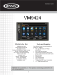
VM9414
What’s in the Box
VM9414 Head Unit
Single DIN Sleeve
Wiring Harness
Parking Brake Sensor Extension Wire
Mounting Hardware
Cosmetic Trim Ring
Remote Control with Battery
3.5mm to 3.5mm Media Adaptor Cable
Owners Manual
Installation Guide
Tools and Supplies
You will need these tools and supplies to install your VM9414:
•
Torx type, flat-head and Philips screwdrivers
•
Wire cutters and strippers
•
Tools to remove existing radio (screwdriver, socket wrench set or other tools)
•
Electrical tape
•
Crimping tool
•
Volt meter/test light
•
Crimp connections
•
18 gauge wire for power connections
•
16 – 18 gauge speaker wire
WARNING! Never install this unit where operation and viewing could interfere with safe driving
conditions.
1
Optional Equipment
•
•
BTM10: Allows you to connect to a Bluetooth enabled cell phone or other device.
Rear Camera
Disconnecting the Battery
To prevent a short circuit, be sure to turn off the ignition and remove the negative (-) battery cable prior to installation.
NOTE: If the VM9414 is to be installed in a car equipped with an on-board drive or navigation computer, do
not disconnect the battery cable. If the cable is disconnected, the computer memory may be lost. Under these
conditions, use extra caution during installation to avoid causing a short circuit.
Pre-installation
1
Remove the four screws that attach the mounting sleeve to the
radio and remove the sleeve.
2
Install the mounting sleeve.
a. Install mounting sleeve into the dashboard or optional
adapter. Do not force the sleeve into the opening or cause
it to bend or bow.
b. Locate the series of bend-tabs along the top, bottom and
sides of the mounting sleeve. With the sleeve fully inserted into the dashboard opening, bend as many of the tabs
outward as necessary so that the sleeve is firmly secured
to the dashboard.
c. Install support strap to make the unit more stable.
3
Place the radio in front of the dashboard opening so the wiring
can be brought through the mounting sleeve.
CAUTION! Be careful not to damage the car wiring.
TAB
TAB
DASHBOARD
DASHBOARD
2
Wiring
WARNING! Only connect the unit to a 12-volt power supply with proper grounding.
Complete wiring as illustrated in the wiring diagram on page 4. Once the wiring is complete, reconnect the battery negative terminal. If there is no ACC available, connect the ACC lead to the power supply with a switch.
NOTE: When replacing a fuse, be sure to use correct type and amperage to avoid damaging the radio. The
VM9414 uses one 15 amp fuse, located in the black filter box in-line with the main wire harness.
Final Installation
After completing the wiring connections, turn the unit on to confirm operation (ignition switch must be on). If
unit does not operate, recheck all wiring until problem is corrected. Once proper operation is achieved, turn off
the ignition switch and proceed with final mounting of the chassis.
1
Connect wiring adapter to existing wiring harness.
2
Connect antenna lead.
3
Carefully slide the radio into the mounting sleeve, making
sure it is right-side-up, and secure with the original 4 screws.
4
Attach one end of the perforated support strap (supplied) to
the screw stud, which is screwed into the threaded insert on
the back of the unit, using the hex nut provided. Fasten the
other end of the perforated strap to a secure part of the
dashboard either above or below the radio using the screw
and hex nut provided. Bend the strap to position it as
necessary.
5
4
5
Replace any items you removed from the dashboard.
ISO-DIN Installation
1
Press
Audi
2
o
VM9
414
VOL
MUTE
NAV
Enter
AV IN
SEL
3
CAUTION! The rear of the radio must be
supported with the strap to prevent damage to the dashboard from the weight of
the radio or improper operation due to
vibration.
NOTE: For proper operation of the CD/
DVD player, the chassis must be mounted
within 20° of horizontal. Make sure the unit
is mounted within this limitation.
1
Remove mounting sleeve brackets.
2
Remove trim ring.
3
Mount factory brackets on new radio using existing screws
from old radio.
4
Slide radio chassis into dash opening and secure.
5
Re-install dash panel.
Enter
AV IN
SEL
Remove Mounting
Sleeve Brackets
Press
LOC
Audio
VM94
ST
14
REP
VOL
LOUD
MUTE
NAV
Enter
AV IN
SEL
3
Wiring Diagram
IMPORTANT: Incorrect wiring connections can damage the unit. Follow the wiring instructions carefully, or
have the installation handled by an experienced technician.
For basic iPod connectivity, you can use the white 30-pin to USB iPod cable that came with your Apple device.
For iPod video playback, you must purchase the jLink-USB cable. Connect the iPod cable to the MediaLink
USB and route the MediaLink USB to an accessible part of the dash area for easy connectivity. For occasional
iPod use, keep an iPod cable in your glove box and use it to connect the iPod to the front USB connector.
Bluetooth Connector
(Connect to optional BTM10)
MULTIZONE
LCH
MONITOR 1
MULTIZONE
RCH
GPS
Antenna
Additional Monitors
Sold Separately
REAR
MONITOR 2
Need Help?
For technical assistance, call the Jensen
customer support line
at 1-800-323-4815.
MONITOR 2
REAR
MONITOR 1
Backup Camera
Sold Separately
CAMERA
jLink USB iPod Interface Cable
(Sold Separately) - Required for iPod
Video Viewing through Head Unit
AUX IN
VIDEO
AUX IN/L
AUX IN/R
NOTE: Steering Wheel Control (SWC)
Requires PAC SWI-PS Interface
Adapter, Sold Separately
MediaLink
USB (included)
SWC
PINK
PARKING BRAKE
PARKING
XM L
Connect to optional XM
Satellite Radio Receiver
with Antenna
XM R
XM RADIO
USB BUS
Harness Cord
LINE OUT
FRONT R
P
External
Power Amplifier
LINE OUT
FRONT L
Ground
GREEN/WHITE
REVERSE +
LINE OUT
REAR R
LINE OUT
REAR L
Gearbox
Switch
ACC
RED
Ignition Switch
ACC
LINE OUT
SUBWOOFER
BATTERY +
YELLOW
BATT
Battery
FUSE (15A)
BLACK
GND
WHITE +
WHITE/BLACK External power amplifier control BLUE/WHITE
P.CONT
Antenna
Auto antenna control (connect to antenna
control lead & power supply of antenna
amplifier)
Car
Phone
PURPLE +
PURPLE/BLACK -
BROWN
MUTE
ORANGE
BATTERY
FRONT L
FRONT R
BLUE
P. ANT
Mute (leave open if not connected)
GREY +
GREY/BLACK -
REAR R
GREEN +
GREEN/BLACK -
ILLUM
4
R
N
D
2
L
REAR L
Ground
Car