1
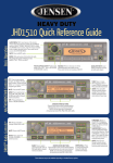
JHD3510
AM/FM/RBDS/WB/CD/AUX-IN/iPod Ready/SIRIUS Ready Heavy Duty Radio
Installation and Operation Manual
JHD3510
CONTENTS
System ................................................................................................................. 1
Safety Information .............................................................................................. 2
Installation ........................................................................................................... 3
Wiring................................................................................................................... 4
Basic Operation .................................................................................................. 5
Tuner Operation .................................................................................................. 7
CD/MP3 Player Operation................................................................................... 9
Satellite Radio Operation ................................................................................. 10
iPod Operation .................................................................................................. 11
Care and Maintenance...................................................................................... 12
Troubleshooting................................................................................................ 12
Specifications ................................................................................................... 13
ii
JHD3510
SYSTEM
Features
Content List
Features of the Jensen JHD3510 mobile audio system include:
•
•
•
•
•
•
•
•
•
•
•
•
•
•
•
•
•
•
•
•
•
•
•
•
Full Dot Matrix LCD
Selectable Amber/Green Backlighting Color
AM/FM US/EURO Tuner with 30 Presets (12 AM, 18 FM)
RBDS (Radio Broadcast Data Service) with PTY Search
SIRIUS Radio Ready
Single In-Dash CD Player with MP3/WMA Playback Capability
CD ESP (Electronic Skip Protection) 40 Sec.
iPod Ready
Weatherband Tuner with NOAA Weather Alert
Mute
Pre-set Equalizer - 5 settings (Flat, Rock, Pop, Classical, Off)
Electronic Bass, Treble, Balance and Fader Controls
Output Power 45W x 4
Clock 12/24 Hour Selectable
Public Announcement (PA) Feature with Optional Microphone
IR Wireless Remote Control Ready (sold separately)
2-Channel Pre-amp Line Level Outputs
2-Wire Power with Non-Volatile Memory and Interior Power Clock/Time Support
Auxiliary Audio Input (Front 3.5mm Stereo Jack, Rear RCA)
Jensen Heavy Duty Radio
Hardware Kit
Wire Harnesses
15AMP Fuse
Installation Manual
FLANGE NUTS
MOUNTING STRAP
DIN SLEEVE
REMOVAL TOOL
MOUNTING BUSHING
MOUNTING SCREW
REAR SPEAKER WIRE HARNESS
15 AMP
FUSE
POWER/FRONT SPEAKER WIRE HARNESS
1
JHD3510
SAFETY INFORMATION
Compatible Disc Types
When Driving
Keep the volume level Iow enough to be aware of the road and traffic conditions.
Table 1: General Disc Information
When Washing Your Vehicle
Do not expose the product to water or excessive moisture. Moisture can cause electrical
shorts, fire or other damage.
Disc Type
Diameter/
Playable Sides
Logo
When Parked
Audio CD
Parking in direct sunlight can produce very high temperatures inside your vehicle. Give the
interior a chance to cool down before starting playback.
12 cm single side
RECORDABLE
Use the Proper Power Supply
Playback Time
74 minutes
REWRITABLE
This product is designed to operate with a 12 volt DC negative ground battery system.
Protect the Disc Mechanism
NOTE: CD-R and CD-RW discs will not play unless the recording session is closed and
the CD is finalized.
Avoid inserting any foreign objects into the disc slot. Misuse may cause malfunction or
permanent damage due to the precise mechanism of this unit.
CAUTION:
Disc Maintenance
THIS MOBILE CD PLAYER IS A CLASS I LASER PRODUCT. THIS UNIT USES A VISIBLE/
INVISIBLE LASER BEAM WHICH COULD CAUSE HAZARDOUS RADIATION IF EXPOSED
DIRECTLY. BE SURE TO OPERATE THE MOBILE CD PLAYER AS INSTRUCTED.
•
A dirty or defective disc may cause sound dropouts while playing. Before playing, wipe
the disc using a clean cloth, working from the center hole towards the outside edge.
Never use benzene, thinners, cleaning fluids, anti-static liquids or any other solvent.
USE OF CONTROLS OR ADJUSTMENTS OR PERFORMANCE OR PROCEDURES OTHER
THAN THOSE SPECIFIED HEREIN MAY RESULT IN HAZARDOUS RADIATION
EXPOSURE.
DO NOT OPEN COVERS AND DO NOT REPAIR BY YOURSELF. PLEASE REFER
SERVICING TO A QUALIFIED TECHNICIAN.
WARNING:
•
•
Insert label
side up.
TO REDUCE THE RISK OF FIRE OR ELECTRIC SHOCK, DO NOT EXPOSE THIS
EQUIPMENT TO RAIN OR MOISTURE.
TO REDUCE THE RISK OF FIRE OR ELECTRIC SHOCK AND ANNOYING
INTERFERENCE, USE ONLY THE RECOMMENDED ACCESSORIES.
DISC NOTES
•
Depending on the recording status, conditions of the disc, and the equipment used for
recording, some CD-Rs/CD-RWs may not play on this unit. For more reliable playback, please
adhere to the following recommendations:
•
•
•
•
•
Use CD-RWs with speed 1x to 4x and write with speed 1x to 2x.
Use CD-Rs with speed 1x to 8x and write with speed 1x to 2x.
Do not play a CD-RW which has been written more than 5 times.
Do not bend.
Never touch
the under side
of the disc.
Wipe clean from
the center to the
edge.
Be sure to use only round CDs for this unit and do not use any special shape CDs. Use of
special shape CDs may cause the unit to malfunction.
Do not stick paper or tape on the disc. Do not use CDs with labels or stickers attached or
that have sticky residue from removed stickers.
Do not expose discs to direct sunlight or heat sources.
NOTE: A disc may become scratched (although not enough to make it unusable)
depending on how you handle it and other conditions in the usage environment. These
scratches are not an indication of a problem with the player.
2
JHD3510
INSTALLATION
This unit is designed for installation in vehicle cabs with an existing 1-DIN radio opening. In
many cases, a special installation kit will be required to mount the radio to the dashboard. See
the dealer where the radio was purchased for kit availability. Always check the kit application
before purchasing to make sure the kit works with your vehicle.
7.
8.
Before You Begin
1.
2.
Disconnect Battery
Before you begin, always disconnect the battery negative terminal.
Remove Transport Screws
Important Notes
•
•
•
•
•
•
Before final installation, test the wiring connections to make sure the unit is connected
properly and the system works.
Use only the parts included with the unit to ensure proper installation. The use of
unauthorized parts can cause malfunctions.
Consult with your nearest dealer if installation requires the drilling of holes or other
modifications to your vehicle.
Install the unit where it does not interfere with driving and cannot injure passengers during
a sudden or emergency stop.
If the installation angle exceeds 30º from horizontal, the unit might not give optimum
performance.
Avoid installing the unit where it will be subject to high temperatures from direct sunlight,
hot air, or from a heater, or subject to excessive dust, dirt or vibration.
DIN Front Mount
1.
2.
3.
4.
5.
6.
Slide the mounting sleeve off of the chasDashboard
sis if it has not already been removed. If it
Bend Tabs
is locked into position, use the removal
182
keys (supplied) to disengage it. The
removal keys are depicted in “Removing
53
the Unit” on page 3.
Screw Stud
Check the dashboard opening size by
sliding the mounting sleeve into it. If the
opening is not large enough, carefully cut
or file as necessary until the sleeve easily
slides into the opening. Do not force the
sleeve into the opening or cause it to bend
or bow. Check that there will be sufficient
space behind the dashboard for the radio chassis.
Locate the series of bend tabs along the top, bottom and sides of the mounting sleeve.
With the sleeve fully inserted into the dashboard opening, bend as many of the tabs
outward as necessary to firmly secure the sleeve to the dashboard.
Place the radio in front of the dashboard opening so the wiring can be brought through the
mounting sleeve.
Follow the wiring diagram carefully and make certain all connections are secure and
insulated with crimp connectors or electrical tape to ensure proper operation.
After completing the wiring connections, turn the unit on to confirm operation (vehicle
accessory switch must be on). If the unit does not operate, recheck all wiring until the
9.
problem is corrected. Once proper operation is achieved, turn the accessory switch off
and proceed with final mounting of the chassis.
Carefully slide the radio into the mounting sleeve making sure it is right-side-up until it is
fully seated and the spring clips lock it into place.
Attach one end of the
perforated support strap
Dashboard
(supplied) to the screw
stud on the rear of the
Support Strap
chassis using the hex nut
Plain Washer
provided. Fasten the
other end of the
Screw (5 x 25mm)
perforated strap to a
Rubber Bushing
Screw Stud
secure part of the
dashboard either above
Hex Nut (5mm)
or below the radio using
the screw and plain
washer provided. Bend
the strap, as necessary,
to position it. Some
vehicle installations
provide cavity for rear
support. In these applications, place the rubber bushing over the screw stud and insert
the radio.
CAUTION: The perforated rear support strap or rear rubber mounting bushing must
be used in the installation of the radio. Installation without either may result in
damage to the radio or the mounting surface and void the manufacturer’s warranty.
Test radio operation by referring to the operating instructions for the unit.
Removing the Unit
To remove the radio after
installation, remove the plastic end
caps, insert the removal keys
straight back until they click, and
then pull the radio out. If removal
keys are inserted at an angle, they
will not lock properly to release the
unit.
Sleeve
Removal Key
Reconnect Battery
When wiring is complete, reconnect
the battery negative terminal.
3
Removal Key
JHD3510
W IR IN G
VIEW A-A
14-PIN CONNECTOR, WIRE INSERTION VIEW
PIN NO.
PA
SOCKET
14-PIN SOCKET
BLACK
BLACK
YELLOW
RED
WHITE
LINE OUT
YELLOW
WHITE
RED
AUX IN (REAR)
A
IPOD IN
(WHITE)
8-PIN
FEMALE
SIRIUS ANTENNA
(GRAY) (BLACK)
8-PIN
FEMALE
WIRE COLOR
VIOLET/BLACK
RIGHT REAR SPEAKER (-)
GRAY/BLACK
RIGHT FRONT SPEAKER (-)
GREEN/BLACK
LEFT REAR SPEAKER (-)
WHITE/BLACK
LEFT FRONT SPEAKER (-)
BLACK
GROUND
EMPTY
NO CONNECTION
EMPTY
NO CONNECTION
VIOLET
RIGHT REAR SPEAKER (+)
GRAY
RIGHT FRONT SPEAKER (+)
GREEN
LEFT REAR SPEAKER (+)
WHITE
LEFT FRONT SPEAKER (+)
RED
+12VDC SWITCHED
BLUE
POWER ANTENNA
EMPTY
NO CONNECTION
VIEW A-A
14-PIN CONNECTOR
RED
15 AMP FUSE
A
.250 FEMALE SPADE
TERMINAL (BLUE WIRE)
4
DESCRIPTION
WARNING!
Do not connect the RED
+12VDC wire to the battery. This
wire MUST be connected to the
Accessory/Ignition wire or a +12
volts switched power source.
JHD3510
BASIC OPERATION
4
15
13
18
21
22
NOTE: CD, IPOD, or Sirius (SAT) mode will be skipped if the module is not installed.
20
NOTE: Sirius (SAT) mode will be skipped when the Region menu option is set to
“EURO”.
23
3
19
Reset
1
14
The reset button should be activated for the following reasons:
17
•
•
•
16
11
8
6
5
7
9
10 2
initial installation of the unit when all wiring is completed
function buttons do not operate
error symbol on the display
Use a ball point pen or thin metal object to press the RESET button (23). This may be
necessary should the unit display an error code.
12
Audio Menu
Press the AUDIO MENU button (3) to access the audio menu. You can navigate through the
audio menu items by pressing the AUDIO MENU button repeatedly. Once the desired menu
item appears on the display, adjust that option by turning the rotary encoder (1) within 5
seconds. The unit will automatically exit the audio menu after five seconds of inactivity. The
following menu items can be adjusted.
Power On/Off
Press the rotary encoder POWER button (1) to turn the unit on or off. The unit will resume at
the last mode selected (Tuner, Aux, etc.).
Bass Level
POWER
Use the rotary encoder (1) to adjust the Bass level range from “-6” to “+6”.
Treble Level
Use the rotary encoder (1) to adjust the Treble level range from “-6” to “+6”.
Balance
Use the rotary encoder (1) to adjust the Balance between the left and right speakers from “12L”
(full left) to “12R” (full right).
Fader
Use the rotary encoder (1) to adjust the Fader between the rear and front speakers from “12R”
(full rear) to “12F” (full front).
Volume Control
To increase the volume, turn the rotary encoder (1) to the right. To decrease the volume, turn
the rotary encoder to the left. While adjusting the volume, the LCD displays a bar graph and
numerical representation of the level. The maximum volume setting is 40.
Mute
Press the MUTE button (16) to mute the audio output. Press MUTE again to restore the audio
output to the previous level.
Mode
Press the MODE button (4) to select a different mode of operation, as indicated on the display
panel. Available modes include Tuner (AM/FM), SAT (Sirius) radio, CD, iPod and AUX in
(optional Auxiliary Input).
5
JHD3510
System Menu
PA Operation
1.
•
2.
3.
Press and hold the AUDIO/MENU button (3) for more than 2 seconds to enter the system
menu. The first menu item, “Beep Tone”, will appear on the display.
Press the AUDIO/MENU button repeatedly to navigate the system menu and select the
desired item.
Use the rotary encoder (1) to adjust the selected menu item.
•
•
•
The following items can be adjusted:
•
•
•
•
•
•
•
•
•
•
•
•
•
•
Liquid Crystal Display (LCD)
Beep Tone (ON/OFF): Turn the audible beep ON/OFF (heard when functions/buttons are
selected).
Region (USA/EURO): Set frequency spacing for various regions.
Time Zone: Set the local time zone (used only for Sirius satellite mode).
DST (Observed/Not Observed): Set for Daylight Savings Time (used only for Sirius
satellite mode).
Clock (12Hr/24Hr): Select 12 or 24 hour display mode.
Brightness (Low/Mid/High): Adjust LCD brightness.
Contrast (Low/Mid/High): Adjust LCD contrast.
Color (Amber/Green): Adjust for desired panel backlight color.
Pwr On Vol (0 – 40): Select an automatic turn-on volume.
iPod Auto (ON/OFF): Choose ”ON” to automatically detect and playback iPod when
connected or “OFF” to use the MODE button to select the iPod source.
TA Volume (0-40): Adjust for desired Traffic Announcement volume level.
WB Alert (ON/OFF): Choose “ON” to switch to Weatherband mode when NOAA weather
alerts are issued. (See “NOAA Weather Alert” on page 8.)
Alert PWR (AUTO/OFF): Select “Auto” to turn on the radio when NOAA alerts are issued.
This function only works when the +12V switched is on.
Default Set (NO/YES): Choose “YES” to return the EEPROM to factory default set up
values.
The current frequency and activated functions are shown on the LCD panel (21).
NOTE: LCD panels may take longer to respond when subjected to cold temperatures for
an extended period of time. In addition, the visibility of the characters on the LCD may
decrease slightly. The LCD display will return to normal when the temperature increases
to a normal range.
Setting the Clock
To set the clock to display the current time, turn the vehicle ignition on and turn the radio off.
Press and hold the DISP/SCROLL button (12) for more than one second and the time will flash
in the display. Press the TUNE/SEEK |<< button (18) to adjust the hours or the TUNE/SEEK
>>| button (19) to adjust the minutes. When in 12Hr Clock mode, “AM” or “PM” will appear on
the display to indicate AM or PM. When no adjustment is made for five seconds, the time will
become set and normal operation will resume.
Scroll
When the information is too long to be displayed on the LCD, press and hold the DISP/
SCROLL button (12) to view the entire title. The information will scroll twice and then return to
abbreviated text.
Equalizer
Press the EQ/LOUD button (11) to choose one of the following pre-defined bass and treble
curves: OFF > FLAT > ROCK > POP > CLAS(SIC).
Loudness
Press and hold the EQ/LOUD button (11) to toggle loudness on/off. When listening to music at
low volumes, this feature will boost the bass and treble ranges to compensate for the
characteristics of human hearing.
Auxiliary Input
To access an auxiliary device:
1.
Connect the portable audio player to either the AUX IN on the front panel (17) or at the
rear of the unit.
2.
Press the MODE button (4) to select “AUX” mode. The rear AUX audio source will play by
default until a device is inserted into the front jack.
Press MODE again to cancel “AUX” mode and go to the next mode.
3.
Connect the PA Microphone with a 4-PIN connector to the 4-PIN socket on the rear of the
unit.
The unit will automatically switch to PA mode when the Mic switch is pushed “ON”.
The PA output level can be adjusted using the rotary volume encoder (1).
With radio power off, the radio will wake up when PA mic is keyed to make an
announcement. Radio will return to off state when PA mic is released.
NOTE: The front AUX IN jack will override the rear auxiliary audio inputs.
6
JHD3510
TUNER OPERATION
Automatically Store / Preset Scan (AS/PS)
4
15
13
18
21
22
20
Automatically Store
Select an AM or FM band. Press and hold the AS/PS (14) button for more than 2 seconds to
automatically select 18 strong stations (6 for each of the three bands). The new stations
replace any stations already stored.
23
Preset Scan
3
19
1
14
Select a band. Press AS/PS (14) to scan stations stored in the current band. The unit will
pause for 5 seconds at each preset station. Press AS/PS again to stop scanning when the
desired station is reached.
RBDS Operation
17
This unit is equipped to display RBDS (Radio Broadcast Data Service) information when
broadcast by the radio station. The following LCD indicators appear when data is received:
16
11
8
6
5
7
9
10 2
•
•
12
RBDS: The current radio station is broadcasting RBDS data.
TA: Traffic Alert mode is activated. When a station broadcasting TA is received, the TA
icon disappears and the 'Traffic' message displays on the LCD.
PTY: Program Type data is being sent. When flashing, PTY search is in progress.
Select a Band
•
Press the BAND/WB button (15) to change between three FM bands and two AM bands.
Press and hold the BAND/WB button to access the Weatherband (WB).
NOTE: Radio stations broadcasting RBDS may not be available in your listening area.
Manual Tuning
Traffic Alert (TA)
Press the TUNE/SEEK >>| or |<< buttons (19, 18) to seek stations up/down step by step.
While in FM radio mode, press and hold the PTY/TA button (13) to activate Traffic Alert mode
and search for a Traffic Alert in your area. From all other modes, press the PTY/TA button to
begin the search.
Auto Seek Tuning
Press and hold the TUNE/SEEK >>| or |<< buttons (19, 18) to automatically seek the next or
previous strong station.
•
Radio Mode: If no TA information is being broadcast, the radio will return to the previously
tuned station.
All other Modes: If a Traffic Alert is being broadcast, playback of the current mode will be
interrupted and the radio will switch to the FM station issuing the TA. Press the PTY/TA
button again to exit TA mode.
NOTE: Seek tuning is not available for weather band channels. Use the up or down
tuning buttons to manually select any of the seven available weather band channels.
•
Preset Stations
Program Type (PTY)
Select a band (if needed), then select a station. Press and hold a preset button (5-10) for two
seconds. The preset number will appear on the LCD.
In FM radio mode, press the PTY/TA button (13) to list the following search options: ANY /
News / Information / Sports / Talk / Rock / Classic Rock / Adult Hits / Soft Rock / Top 40 /
Country / Oldies / Soft / Nostalgia / Jazz / Classical / Rhythm and Blues / Soft Rhythm & Blues
/ Foreign Language / Religious Music / Religious Talk / Personality / Public / College / Weather
/ Emergency Test / ALARM! ALARM!
Recall a Station
To search for stations in a PTY category:
Select a band (if needed). Press a preset button (5-10) to select the corresponding stored
station.
1.
2.
NOTE: Preset buttons are pre-assigned frequencies in weather band mode.
3.
Six numbered preset buttons store and recall stations for each band.
Store a Station
Press the PTY/TA button (13) to view the current PTY category.
Use the rotary encoder knob (1) to move through the list of available categories and
select the program type you wish to search.
After selecting the desired PTY, press and hold the TUNE/SEEK >>| or |<< button (19, 18)
to search the band for broadcasts of this type.
NOTE: Performing a PTY search on “ANY” will Seek Tune and stop on any station
broadcasting RBDS, regardless of the program type.
7
JHD3510
Weather Band Operation
What is the NOAA Weather Radio/Weatheradio Canada?
This is a nationwide system that broadcasts local weather emergency information 24 hours a
day. The U.S. network has more than 530 stations covering the 50 states as well as the
adjacent costal waters, Puerto Rico, the U.S. Virgin Islands and the U.S. Pacific Territories.
Each local area has its own transmitting station and there are a total of seven broadcasting
frequencies used. A similar system is available in Canada under the Weatheradio Canada
service administered by Environment Canada.
Tuning to Weatherband
Press and hold the BAND/WB button (15) to access the Weatherband. The indication "WB"
will appear on the display panel, along with the current number and channel indication:
"CH01", CH02", "CH03", "CH04", "CH05", "CH06" or "CH07". Use the TUNE/SEEK >>| or |<<
buttons (19, 18) to tune to each of the seven channels until you find the weatherband station
broadcasting in your area.
How many stations can I expect to receive?
Since the broadcasts are local weather and information, the transmission power is usually very
low (much less than standard AM or FM stations) so you will usually receive only one station
unless you are on the edge of two or more broadcast signals. The most you will receive will be
two or three, and that is rare.
Is it possible I won't receive any stations?
Depending on where you are located, there is a possibility you will receive only a very weak
signal or none at all. Also, similar to AM and FM signals, weatherband signals are subject to
surrounding conditions, weather, obstructions of the signal by hills or mountains, etc.
NOAA Weather Alert
The Weather Alert function adds an additional level of user safety by automatically switching
from any of the available function modes (Tuner, SAT, CD, iPod, AUX) to weather band for a
minimum of 60 seconds if a NOAA warning tone (1050 Hz) is received/detected. If no
additional warning tone is received for 60 seconds, the unit will switch back to the last known
function mode. See “System Menu” on page 6 to learn how to turn the WB Alert feature on.
8
JHD3510
CD/MP3 PLAYER OPERATION
Folder Navigation (MP3 Only)
4
15
13
18
21
22
Press the 5/DN button (9) to select folder down.
20
Press the 6/UP button (10) to select folder up.
MP3 Playback
23
3
19
1
14
Notes on MP3 Playback
•
Any directory that does not include an MP3 file is skipped
•
Maximum number of folders: 512 (including skipped directories)
•
Maximum number of folder levels: 12
•
Maximum number of MP3 files: 999
•
Maximum number of characters for MP3 file name and folder name: 32
•
Sampling frequency: 16KHz, 22.05KHz, 24KHz, 32KHz, 44.1KHz, 48KHz
•
Bit rates: maximum 384 Kbps
•
Maximum number of Characters of ID3 Tag:
•
ID3 Tag version 1.0: 32
•
ID3 Tag version 2.x: 32
17
16
11
8
6
5
7
9
10 2
12
File Playing Order
Inserting and Ejecting a Disc
When selected for play, files and folders (Folder Search, File Search or Folder Select) are
accessed in the order they were written by the CD writer. As a result, the order in which they
are expected to be played may not match the order in which they are actually played. You may
be able to set the order in which MP3/WMA are to be played by writing them onto a medium
such as a CD-R with their file names beginning with play sequence numbers such as "01" to
"99".
Insert a disc, label-side up, into the disc slot (22). The unit will automatically draw the disc in
and play the first track on the disc, whether the power was turned on or not.
Press the eject button (20) to stop disc play and eject the disc. The unit does not have to be
on to eject the disc.
Controlling Disc Playback
For example, a medium with the following folder/file hierarchy is subject to Folder Search, File
Search and playback order as shown below.
Selecting Tracks
Press the TUNE/SEEK >>| (19) or TUNE/SEEK |<< button (18) to advance to the next track on
the disc. The selected track number will appear on the display. Press and hold the TUNE/
SEEK >>| or |<< button to fast forward or fast reverse through the disc. Disc play starts when
the button is released.
Play/Pause Disc Playback
Press the 1/>|| button (8) to suspend disc play. Press the 1/>|| button again to resume disc
Play.
Previewing Tracks
Press the 2/INT button (6) to play the first 10 seconds of each track sequentially. Press 2/INT
again to stop Intro Scan and resume normal play at the current track.
Repeat Play
•
Press the 3/RPT button (5) during disc play to repeat the current track.
•
Press and hold the 3/RPT button to repeat the current folder.
•
Press 3/RPT again to stop repeat play.
Random Play
•
Press the 4/RDM button (7) during disc play to play all tracks in random, shuffled order.
•
Press and hold the 4/RDM button to randomly play all files in the current folder.
•
Press 4/RDM again to stop random play.
9
JHD3510
SATELLITE RADIO OPERATION
4
15
13
18
21
22
Programming Channels
1. Select the channel you want to store in memory.
2. Press and hold a preset button (5-10) until the corresponding preset button number
appears.
3. Repeat steps 1 and 2 to program additional channels.
20
23
Preset Recall
3
19
Press one of the six preset buttons (5-10) to directly select a preset channel stored in the
current band.
1
14
Preset Scan
17
Press AS/PS (14) to scan stations stored in all three user-preset channel groups (SR1, SR2
and SR3). The unit will pause for 10 seconds at each preset station. Press AS/PS again to stop
scanning when the desired station is reached.
Preset Tuning
16
11
8
6
5
7
9
10 2
Press and hold the AS/PS button (14) to access Preset Tuning Mode. In Preset Tuning Mode,
you can use the TUNE/SEEK |<< / >>| buttons (18, 19) to access all 18 preset stations in
sequential order. Press and hold the AS/PS button again to deactivate Preset Tuning Mode.
12
Switching to Sirius Satellite Radio
(Requires optional Sirius tuner)
Alternate Display Mode
Press the MODE button (4) to change the mode to Sirius radio mode.
Press the DISP/SCROLL button (12) to change the display information between single and
dual line text display. In dual line mode, both artist and title are available for viewing.
Accessing your Sirius RADIO ID
Press and hold the DISP/SCROLL button to scroll the Artist/Song Title information.
To display your Sirius radio ID, use the TUNE/SEEK |<< button to tune to channel “000”. The
screen will display “Sirius ID” on the top bar with the SID displayed in the middle of the LCD
screen. The Sirius radio ID is 12 characters long.
Satellite Signal Strength
The display will indicate satellite reception strength as shown below.
Selecting a Band
Signal Strength
In Sirius mode, press the BAND/WB button (15) to access the Sirius user-preset channel
groups in the following order: SR1, SR2, SR3.
No Signal
Category Tuning
1.
2.
3.
4.
5.
Strength Display
Weak
Press the S-MOD/ENTER button (2) to access Category mode.
While the category is flashing, press TUNE/SEEK |<< / >>| buttons (18, 19) to choose a
category.
Press the S-MOD/ENTER button to confirm category selection and tune to the first
channel in the selected category. The category icon will stop flashing.
Press the TUNE/SEEK |<< / >>| buttons (18, 19) to choose desired channels in that
category. (The lowest channel number within the chosen category will always be the
default first channel tuned.)
Press and hold the S-MOD/ENTER button to return to channel tuning mode.
Good
Excellent
Channel Lock
While tuned to the channel to be locked, press and hold the MODE button (4) to access the
Channel Lock function. “Enter Code” is displayed on the LCD. Using the 1-6 digit buttons, enter
your 4-digit code (the default code is 1111). “Channel Locked” appears on the LCD, confirming
that the channel has been locked. The next time the channel is sequentially accessed, the
“Channel Locked” message will appear, followed by “Enter Code”. To retrieve the locked
channel, enter your 4-digit code. To change the channel lock code, press and hold the PTY/TA
button (13). Enter Current Code > New Code > Confirm. The LCD will display “New Code
Stored”.
Channel Up/Down Tuning
Press the TUNE/SEEK |<< / >>| buttons (18, 19) to search for a channel. Press and hold the
TUNE/SEEK buttons to fast search.
Storing Preset Channels
The preset buttons (5-10) can be used to store 6 channels, allowing convenient access to your
favorite channels.
10
JHD3510
iPod OPERATION
Controlling Playback
This unit is equipped with an iPod ready function that will allow you to control your iPod (if
compatible) using the control panel buttons. The following iPod versions are supported:
•
•
•
•
•
•
Pausing Playback
iPod 3G (firmware version 2.2 only)
iPod Mini
iPod 4G
iPod Photo
iPod Nano
iPod 5G (Video)
During playback, press the 1/>|| button (8) to pause the iPod player. “Pause” will appear on the
LCD. Press 1/>|| again to resume playback.
Repeat Play
During playback, press the 3/RPT button (5) to repeat the current song. “Repeat” will appear
on the LCD. Press 3/RPT again to stop repeat playback.
Random Play
During playback, press the 4/RDM button (7) to play all songs in the current category in
random order. Random play will begin once the current song has finished playing. “RANDOM”
will appear on the LCD. Press 4/RDM again to stop random playback.
NOTE: iPod and iPod Cable sold separately.
Accessing iPod Mode
Selecting Tracks
To enter iPod mode from any other source, press
the MODE button (4) until “iPod” appears on the
display.
8 Din iPod Ready Cable
During playback, press the TUNE/SEEK |<< / >>| button (18, 19) to play the previous or next
track in the current category. Press the TUNE/SEEK |<< button (18) once to play the song from
the start position or press TUNE/SEEK |<< twice to play the previous track.
HEAD UNIT
Turning the iPod On/Off
Press and hold the TUNE/SEEK |<< / >>| button (18, 19) to fast reverse/forward the song.
The iPod power turns on automatically when an
iPod is connected to the 30-pin iPod cable, as long
as the vehicle ignition is turned on. You can turn
the iPod off by disconnecting it from the cable or by
turning the ignition off. When the ignition is turned
off, the iPod will pause and then enter sleep mode
after 2 minutes. While the iPod is connected, the
power cannot be turned on or off from the iPod
itself.
NOTE: If you press and hold the TUNE/SEEK |<< / >>| button to change the current song
to the previous/next song, you will exit fast reverse/forward mode.
iPod
Video
iPod
photo
iPod
iPod
mini
iPod
nano
Category Search
Press the S-MOD/ENTER button (2) to access Category selection mode. While in Category
mode, repeatedly press the S-MOD/ENTER button to choose file search by Playlist, Artist,
Album, Genre, or Song. After choosing a search category, use the 5/DN (9) and 6/UP (10)
buttons to search the available files on the iPod. Press the 1/>|| button (8) to play the selected
Playlist, Artist, Album, Genre, or Song.
iPod Cable
NOTE: The iPod will continuously recharge when connected to the unit, as long as the
vehicle ignition is turned on.
Alternate Display Mode
Press the DISP/SCROLL button (12) to change the display information between single and
double line text display.
4
15
13
18
21
22
20
23
3
19
1
14
17
16
11
8
6
5
7
9
10 2
12
11
JHD3510
CARE AND MAINTENANCE
•
•
•
•
•
TROUBLESHOOTING
Keep the product dry. If it does get wet, wipe it dry immediately. Liquids might contain
minerals that can corrode the electronic circuits.
Keep the product away from dust and dirt, which can cause premature wear of parts.
Handle the product gently and carefully. Dropping it can damage circuit boards and
cases, and can cause the product to work improperly.
Wipe the product with a dampened cloth occasionally to keep it looking new. Do not use
harsh chemicals, cleaning solvents, or strong detergents to clean the product.
Use and store the product only in normal temperature environments. High temperature
can shorten the life of electronic devices, damage batteries, and distort or melt plastic
parts.
Symptom
No power
Disc cannot be loaded or
ejected
Cause
Solution
The vehicle’s accessory
switch is not on
If the power supply is properly
connected to the vehicle’s accessory terminal, switch the ignition
key to “ACC” or “Run”
The fuse is blown
Replace the fuse
Presence of CD disc inside
the player
Remove the disc in the player and
insert the new one
If disc will not eject, press the
RESET button
Ignition
The most common source of noise in reception is the ignition system. This is a result of the
radio being placed close to the ignition system (engine). This type of noise can be easily
detected because it will vary in intensity of pitch with the speed of the engine.
Inserting the disc in reverse
direction
Insert the compact disc with the
label facing upward
Usually, the ignition noise can be suppressed considerably by using a radio suppression type
high voltage ignition wire and suppressor resistor in the ignition system. (Most vehicles employ
this wire and resistor but it may be necessary to check them for correct operation.) Another
method of suppression is the use of additional noise suppressors. These can be obtained from
most professional mobile electronics retailers.
Compact disc is extremely
dirty or disc is defective
Clean the disc or try to play a new
one
Condensation
Leave the player off for an hour or
so, then try again
Volume is too low or system
is muted
Adjust volume to audible level
Wiring is not properly connected
Check wiring connections
The operation keys do
not work
The built-in microcomputer
is not operating properly
due to noise
Press the RESET button
Sound skips
The installation angle is
more than 30 degrees
Adjust the installation angle to
less than 30 degrees
The disc is dirty or defective.
Clean the disc and try to play
again or use new disc
The antenna cable is not
connected
Check antenna cable
The signals are too weak
Select a station manually
No sound
Interference
Radio reception in a moving environment is very different from reception in a stationary
environment (home). It is very important to understand the difference.
AM reception will deteriorate when passing under a bridge or when passing under high voltage
lines. Although AM is subject to environmental noise, it has the ability to received at great
distance. This is because broadcasting signals follow the curvature of the earth and are
reflected back by the upper atmosphere.
Cannot tune to radio station, auto-seek does not
work
12
JHD3510
SPECIFICATIONS
CD
Signal to Noise Ratio. . . . . . . . . . . . . . . . . . . . . . . . . . . . . . . . . . . . . . . . . . . . . . . . . > 65 dB
Channel Separation . . . . . . . . . . . . . . . . . . . . . . . . . . . . . . . . . . . . . . . . . . : More than 50 dB
Frequency Response . . . . . . . . . . . . . . . . . . . . . . . . . . . . . . . . . . . . . . . . . . : 20 Hz - 20 kHz
FM Radio
Frequency Coverage (USA) . . . . . . . . . . . . . . . . . . . . . . . . . . . . . . . . . . . 87.5 to 107.9 MHz
Frequency Coverage (Europe) . . . . . . . . . . . . . . . . . . . . . . . . . . . . . . . . . . . 87.5 to 108 MHz
Sensitivity (S/N=30dB) . . . . . . . . . . . . . . . . . . . . . . . . . . . . . . . . . . . . . . . . . . . . . . . . . . . 4µV
Image Rejection . . . . . . . . . . . . . . . . . . . . . . . . . . . . . . . . . . . . . . . . . . . . . . . . . . . . . >45 dB
Stereo Separation . . . . . . . . . . . . . . . . . . . . . . . . . . . . . . . . . . . . . . . . . . . . . . . . . . . . >25 dB
AM/MW
Frequency Range (USA). . . . . . . . . . . . . . . . . . . . . . . . . . . . . . . . . . . . . . . . . 530-1710 kHz
Frequency Range (Europe). . . . . . . . . . . . . . . . . . . . . . . . . . . . . . . . . . . . . . . 522-1620 kHz
Sensitivity (S/N=20dB) . . . . . . . . . . . . . . . . . . . . . . . . . . . . . . . . . . . . . . . . . . . . . . . . . 36 dB
General
Operating Voltage . . . . . . . . . . . . . . . . . . . . . . . . . . . . . . . . . . . . . . . . . . . . . . . . .DC 12 Volts
Grounding System . . . . . . . . . . . . . . . . . . . . . . . . . . . . . . . . . . . . . . . . . . . Negative Ground
Speaker Impedance . . . . . . . . . . . . . . . . . . . . . . . . . . . . . . . . . . . . . . .4-8 ohms per channel
Tone Controls:
Bass (at 100 Hz) . . . . . . . . . . . . . . . . . . . . . . . . . . . . . . . . . . . . . . . . . . . . . . . . . : ±10 dB
Treble (at 10 kHz). . . . . . . . . . . . . . . . . . . . . . . . . . . . . . . . . . . . . . . . . . . . . . . . . : ±10 dB
Power Output . . . . . . . . . . . . . . . . . . . . . . . . . . . . . . . . . . . . . . . . . . . . . . . . . . . . . . 45W x 4
Idle/Standby Current . . . . . . . . . . . . . . . . . . . . . . . . . . . . . . . . . . . . . . . . . . . . . . . . . . . 75mA
Current Drain. . . . . . . . . . . . . . . . . . . . . . . . . . . . . . . . . . . . . . . . . . . . . . . .15 Ampere (max.)
Dimensions . . . . . . . . . . . . . . . . . . . . . . . . . . . . . . . . . . . . . . . . . . . 80 (W) x 183 (D) x 58 (H)
13
ASA Electronics Corporation
www.asaelectronics.com
©2007 ASA Electronics Corporation
v.081707