1
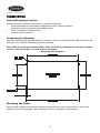
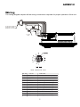
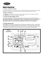
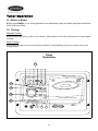
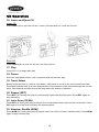
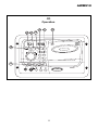
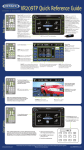
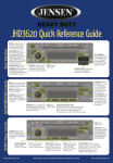
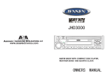
AWM910
Owner’s Manual
COMPACT DISC PLAYER
PUSH
1
2
RPT
3
SCAN
4
6
M
5
H
RDM
PUSH PWR
VOL
ALARM
SET
EQ
ON/OFF
T/F
AUD
MUTE
AUX
BAND
RADIO CD COMPACT MUSIC SYSTEM
CD
AUX IN
SPK
A
SPK
B
SPK
A+B
JENSEN
AWM910
Thank You!
Thank you for choosing a Jensen product. We hope you will find the instructions in this owner’s
manual clear and easy to follow. If you take a few minutes to look through it, you’ll learn how to
use all the features of your new Jensen receiver for maximum enjoyment.
Table of Contents . . . . . . . . . . . . . . . . . . . . . . . . . . . . . . . . . . . . . . . . . . . . . . . . . . . . . . . . . 2
Features . . . . . . . . . . . . . . . . . . . . . . . . . . . . . . . . . . . . . . . . . . . . . . . . . . . . . . . . . . . . . . . . . 3
Installation . . . . . . . . . . . . . . . . . . . . . . . . . . . . . . . . . . . . . . . . . . . . . . . . . . . . . . . . . . . . . . . 4
Wiring . . . . . . . . . . . . . . . . . . . . . . . . . . . . . . . . . . . . . . . . . . . . . . . . . . . . . . . . . . . . . . . . . . . 5
Basic Operation. . . . . . . . . . . . . . . . . . . . . . . . . . . . . . . . . . . . . . . . . . . . . . . . . . . . . . . . . . . 6
Tuner Operation . . . . . . . . . . . . . . . . . . . . . . . . . . . . . . . . . . . . . . . . . . . . . . . . . . . . . . . . . . 8
CD Operation . . . . . . . . . . . . . . . . . . . . . . . . . . . . . . . . . . . . . . . . . . . . . . . . . . . . . . . . . . . . . 10
Specifications . . . . . . . . . . . . . . . . . . . . . . . . . . . . . . . . . . . . . . . . . . . . . . . . . . . . . . . . . . . . 12
2
AWM910
Features
Features of the Jensen AWM910 mobile audio system include:
•
Auto Dimming LCD Display Backlighting
•
Backlit Controls and Display
•
Electronic AM/FM Tuner
•
Three preset EQ Modes
•
Rotary Volume Control
•
Time/Alarm Clock
•
Vertical CD Mechanism for Audio CD, CD-R, CD-RW
•
4-Channel Amplified Audio Output (50W Total)
•
Front Aux Audio Input (3.5mm stereo jack)
•
¼" Headphone Output on Front Panel
3
Installation
Select Mounting Location
Select a mounting location, taking care to avoid the following:
•
•
•
•
Places exposed to heat-radiating appliances such as electric heaters
Adjacent to other equipment that radiates heat
Poorly-ventilated or dusty places
Moist or humid locations
Preparing the Opening
Use the mounting hole diagram (below) to measure and cut a mounting hole, and mount the unit
using the four 3x20mm self-tapping screws provided.
Note: Before cutting the mounting hole, make sure the area behind the mounting location
is clear of wires and fuel, vacuum and or brake lines.
Mounting Hole Diagram
Mounting the Radio
Route power, speaker and antenna cables through the hole, and connect them to the unit as
outlined in the wiring diagram. After ensuring correct connections, test operation.
4
AWM910
Wiring
The wiring diagram depicts all the wiring connections required for proper operation of the unit.
A
A
12 PIN AMP CONNECTOR
P/N 480708-0 W/AMP
TERMINALS P/N 350536-1
7.5 AMP
FUSE
FILTER&
FUSE BOX
1 AMP
FUSE
WIRE INSERTION VIEW
PIN NO
1
2
3
4
5
6
7
8
9
10
11
12
COLOR
FUNCTION
BLACK
POWER GROUND (-12VDC)
YELLOW
+12VDC BATTERY POWER
RED
+12VDC SWITCHED POWER
VIOLET
RIGHT (B) SPEAKER (+)
GRAY/BLACK
RIGHT (A) SPEAKER (-)
WHITE
LEFT (A) SPEAKER (+)
VIOLET/BLACK RIGHT (B) SPEAKER (-)
GREEN
LEFT (B) SPEAKER (+)
WHITE/BLACK LEFT (A) SPEAKER (-)
BLUE
+12VDC TRIGGER
GREEN/BLACK LEFT (B) SPEAKER (-)
GRAY
RIGHT (A) SPEAKER (+)
5
Basic Operation
1. Power / Volume Control
Press the power button (1) to turn the unit on or off. This button also serves as the volume control
knob; rotate clockwise or counterclockwise to increase or decrease the volume output.
2. Mute / Loudness
Press MUTE (2) momentarily to silence the audio output in tuner, CD or auxiliary input mode.
Press MUTE again to resume the previous volume level.
3. Liquid Crystal Display (LCD)
The liquid crystal display (LCD) panel (3) displays the frequency, time and activated functions.
Note: When subjected to cold temperatures for an extended period of time, LCD panels will
take longer to illuminate and the display visibility may slightly decrease. Optimal LCD
operation will return to normal when the temperature increases to a normal range.
4. Audio Adjustment
Press AUD (4) momentarily to step through the following audio adjustment options: Volume, Bass,
Treble, Balance (left to right) and Speaker (A to B) and Fader (front to back). When the desired
option appears in the display, rotate the volume control knob (1) to adjust that audio feature. When
no adjustments have been made for three seconds, the unit will resume normal operation.
Basic
Operation
3
7b
7a
6
COMPACT DISC PLAYER
8b
8a
PUSH
1
2
RPT
3
SCAN
4
6
M
5
H
RDM
PUSH PWR
VOL
ALARM
SET
1
EQ
10
T/F
RADIO CD COMPACT MUSIC SYSTEM
AUD
2
MUTE
5
ON/OFF
AUX
BAND
CD
AUX IN
SPK
A
SPK
B
SPK
A+B
9
JENSEN
4
6
AWM910
AWM910
5. Auxiliary Input Function
Press AUX (5) to directly access auxiliary input mode from any other function mode when
portable audio device is connected to the unit. To connect a portable audio device, insert a
standard 3.5 mm (audio line output or headphone output from your portable CD / MP3 / iPod or
other media player) into an “AUX IN” jack on the front or rear of the unit.
Note: For front panel AUX input, and external audio source such as an audio (MP3) player
can be connected to the front panel AUX input with a separately purchased 3.5mm cable
adapter. Connect the device to the AUX input on the front panel and press AUX to engage
the input circuit.
6. Time/Frequency Display
Press T/F (6) momentarily to display the time while in Tuner, CD or auxiliary input mode.
7. Setting the Clock
Press T/F (6) to display the clock. Press and hold T/F, and the clock display will flash. While
holding T/F, press H (7a) to adjust the hour or M (7b) to adjust the minute. The new time will be
saved five seconds after the last adjustment is made.
8. Setting the Alarm
To set the alarm to a specific time, press and hold ALARM SET (8a), and the alarm time will flash
in the display. While holding ALARM SET, press H (7a) to adjust the hour or M (7b) to adjust the
minute. The new alarm time will be saved five seconds after the last adjustment is made.Once a
time is set, press ALARM ON/OFF (8b) to turn the alarm function on or off.
9. Speaker Output
The three speaker output buttons (9) (SPK A, SPK B and SPK A+B) control speaker output from
the radio. Press any of the three buttons to turn the corresponding speaker on or off. The red light
above each button will illuminate when that speaker is turned on.
10. Reset
Use a ballpoint pen or other thin metal object to press the reset button (10) under the following
circumstances: after the completion of initial installation/wiring, if none of the function buttons
work or if an error symbol appears in the display.
7
Tuner Operation
11. Select a Band
Briefly press BAND (11) to change between two AM bands (AM1 and AM2) and three FM bands
(FM1, FM2 and FM3).
12. Tuning
Manual Tuning
Briefly press the tune up (12a) or tune down (12b) buttons to tune the frequency one step higher
or lower.
Seek Tuning
Press and hold the tune up or tune down buttons to automatically tune up or down to the next
strong station.
Tuner
Operation
13
COMPACT DISC PLAYER
PUSH
12a
1
2
RPT
3
SCAN
4
6
M
5
H
RDM
PUSH PWR
VOL
12b
ALARM
SET
14
EQ
ON/OFF
T/F
RADIO CD COMPACT MUSIC SYSTEM
AUD
11
MUTE
AUX
BAND
CD
AUX IN
SPK
A
SPK
B
JENSEN
SPK
A+B
8
AWM910
AWM910
13. Preset Stations
Store Preset Stations
Six numbered preset buttons (13) store and recall stations for each AM and FM band. To store a
station, select a band (if needed), then select a station. Hold a preset button for three seconds.
The current station will be stored, and the corresponding preset number will appear in the display.
Recall Preset Stations
To recall a station, select a band (if needed). Press a preset button momentarily, and the unit will
tune to the corresponding stored station.
14. Equalizer Selector
The equalizer function applies preset sound effects to the unit’s audio output signal. Press EQ
(14) to step through the following equalizer options: Rock, Pop, Classic and USER. The equalizer
options will appear in the display as they are accessed. The Bass and Treble settings will be
saved in USER mode.
15. Headphone Operation
The headphone output is wired to the "A" speaker and is active when either "A" or "A & B"
speaker button is active. To use this feature, plug the headphones in to the 1/4" jack (15) and
adjust the volume to the desired level. When the headphones are plugged in, the speakers are
automatically disabled.
9
CD Operation
16. Insert and Eject CD
Insert CD
Press PUSH (16) to open the CD door. Insert a CD label-side out. Close the CD door.
Eject CD
Press PUSH again to open the CD door and stop CD play.
17. Play
Press CD (17) to begin disc play.
18. Pause
Press the play/pause button (18) to suspend and resume disc play.
19. Track Select
Briefly press the tune up (19a) or tune down (19b) button to move to the next or previous track.
Press and hold the tune up or tune down button to fast forward or fast reverse through the current
track. Fast forward and fast reverse will stop when the button is released.
20. Repeat (RPT)
Press RPT (20) during disc play to continuously repeat the selected track. Press RPT again to
stop repeating.
21. Intro Scan (SCAN)
Press INT(21) during disc play to play the first 10 seconds of each track on the current disc. Press
INT again to end the scan and play the selected track.
22. Random Shuffle (RDM)
Press RDM (22) during disc play to play all tracks on a CD in random, shuffled order. Press RDM
again to stop random play.
10
AWM910
CD
Operation
19b
16
19a
20 21 22
COMPACT DISC PLAYER
PUSH
18
1
2
RPT
3
SCAN
4
6
M
5
H
RDM
PUSH PWR
VOL
ALARM
SET
EQ
ON/OFF
T/F
RADIO CD COMPACT MUSIC SYSTEM
AUD
17
MUTE
AUX
BAND
CD
AUX IN
SPK
A
SPK
B
JENSEN
SPK
A+B
11
AWM910
Specifications
General
Power Supply Requirements. . . . . . . . . . . . . . . . . . . . . . . . . . DC 12 Volts, Negative Ground
Operating Voltage . . . . . . . . . . . . . . . . . . . . . . . . . . . . . . . . . . . . . . . . . . . . . . . . . . 10-16VDC
Overall Dimensions . . . . . . . . . . . . . . . . . . . . . . . . . . . . . . . . 10-7/16"(W) x 7"(H) x 6-1/4"(D)
Mounting Dimensions . . . . . . . . . . . . . . . . . . . . . . . . . . . . . 9-3/8"(W) x 6-1/8"(H) x 6-1/4"(D)
Weight . . . . . . . . . . . . . . . . . . . . . . . . . . . . . . . . . . . . . . . . . . . . . . . . . . . . . . . 3.5 lbs.(1.7 Kg)
FM Tuner
Tuning range . . . . . . . . . . . . . . . . . . . . . . . . . . . . . . . . . . . . . . . . . . . . . . . . . . . 87.5-107.9FM
Sensitivity . . . . . . . . . . . . . . . . . . . . . . . . . . . . . . . . . . . . . . . . . . . . . . . . . . . . . . . . . . . . <5uV
Stereo separation @ 1 kHz . . . . . . . . . . . . . . . . . . . . . . . . . . . . . . . . . . . . . . . . . . . . . . >30dB
AM Tuner
Tuning range . . . . . . . . . . . . . . . . . . . . . . . . . . . . . . . . . . . . . . . . . . . . . . . . . . . . . . .530-1710
Sensitivity . . . . . . . . . . . . . . . . . . . . . . . . . . . . . . . . . . . . . . . . . . . . . . . . . . . . . . . . . . . <30uV
CD Player
Frequency Response . . . . . . . . . . . . . . . . . . . . . . . . . . . . . . . . . . . . . . . . . . 20Hz to 20kHz
Signal to Noise . . . . . . . . . . . . . . . . . . . . . . . . . . . . . . . . . . . . . . . . . . . . . . . . . . . . . . . 65dB
Compatible CD Formats . . . . . . . . . . . . . . . . . . . . . . . . . . . . . . . . . . . Audio CD, CD-R, R/W
Amplifier
Output Power . . . . . . . . . . . . . . . . . . . . . . . . . . . . . . . . . . . . . . . . . . . . 25 Watts per Channel
Output Wiring . . . . . . . . . . . . . . . . . . . . . . . . . . . . . . . . 2/4 Speaker and Headphone System
Output Impedance . . . . . . . . . . Compatible with 4-8 Ohm Speakers, 4 Ohm Load Minimum
Total system power . . . . . . . . . . . . . . . . . . . . . . . . . . . . . . . . . . . . . . . . . 50 Watts Maximum
Specifications subject to change without notice.
This device complies with Part 15 of the FCC Rules. Operation is subject to the following two
conditions:
(1) This device may not cause harmful interference, and
(2) This device must accept any interference received, including interference that may cause
undesired operation.
Note: The manufacturer is not responsible for any radio or TV interference caused by
unauthorized modifications to this equipment. Such modifications could void the User’s
authority to operate the equipment.
www.asaelectronics.com
© 2006 ASA Electronics Corporation
v.120606
12