Transcript
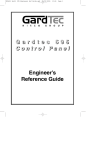
!
WARNING
Risk of electric shock
- Do not use in wet locations.
- Use indoors only.
- Turn power off before servicing see instructions.
- Properly ground fixture.
- Ensure that no bare wires are exposed
outside the electrical connections.
- Use within electrical rating of device
**This device is intended for use only with
GE Linkable products. Use of any other
lighting product may be hazardous.
10) Install the conduit or armored cable to meet
electrical codes. Tighten the two screws on
the strain relief connector to secure the wires.
11) Connect the hot (black) AC supply wire(s) to
the hot (black) wire in the electrical box.
Secure the connection with the wire nuts
provided. See Figure 1.
12) Connect the white (neutral) AC supply wire(s)
to the neutral (white) wire in the electrical box.
Secure the connection with the wire nuts
provided. See Figure 1.
13) Connect the ground (green or copper) AC
supply wire to the copper ground wire of the
electrical box. Secure the connection with
the wire nuts provided. If your electrical
system contains no grounding wire, you
should consult a qualified electrician before
proceeding with the installation. See Figure 1.
14) Ensure that no bare wires are exposed after
making the electrical connections.
15) Arrange the wires inside the fixture and
reattach the plastic cover of the electrical
box. Tighten the screws to ensure that all
the wires and connections are sealed
properly inside the fixture without "pinching"
any wires.
INSTALLATION PROCEDURES
FOR ELECTRICAL BOX
1) Consult a local licensed electrician or
electrical contractor if you are not sure
about the installation.
2) Ensure that electricity is TURNED OFF at the
main circuit breaker or fuse box. DO NOT
ATTEMPT TO INSTALL ELECTRICAL BOX
WITH THE POWER ON.
3) Select a suitable dry mounting location
(for use indoors only). Make sure the
Figure 1
mounting surface is capable of supporting
Quick Connect
the fixture.
4) Remove plastic cover from electrical
Hot (Black)
mounting box by unscrewing the 2 screws.
Ground Box Wire
(Green or
5) Choose a suitable knock-out location from
Copper)
those provided on the box. Remove the
Wires
knock-out with a screw driver. See Figure 1.
AC
Supply
6) Place the electrical box in the location where
Neutral (White)
Wires
Box Wire
it is to be mounted and mark the position of
the mounting slots with a pencil.
7) It is recommended that a 1/16" pilot hole be
drilled in the mounting surface.
Strain
8) Drive the screws provided in the mounting
Relief
Neutral (White)
Knock Hot (Black)
hardware into the mounting surface until the
Supply Wire
Out Supply Wire
electrical box is secure.
9) Insert the threaded end of the strain relief
(provided in the installation kit) into the selected
knock out opening on the electrical box. Place
the eyelet of the grounding (copper) wire provided
in the installation kit around the strain relief. The
grounding (copper) wire & eyelet should be
located inside of the box. Secure the strain
UCF012-front
relief by tightening the lock nut. See Figure 1.
24772-2 rev11/18/05