1
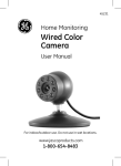
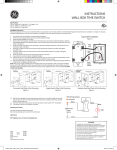
INSTRUCTIONS
WALL BOX TIME SWITCH
CAUTION:
15305
Installation by a licensed electrician is recommended. Installation and use of this equipment should be in accordance with provisions of the U.S. National
Electrical Code, applicable local codes and pertinent industry standards.
These timers are not to be used in precision timing applications when inaccurate timing could have dangerous consequences such as with sun lamps or in
tanning booths.
Do not use to control receptacles.
For indoor use only unless installed in a, NEMA type 3R enclosure.
Use only copper wire.
Specifications:
20A, 125VAC General Purpose
10A, 250VAC General Purpose
10A, 277VAC General Purpose
7A, 125VAC Tungsten
1HP, 125VAC
1HP, 250VAC
Installation Instructions
This GE Spring Wound Timer is easy to install and will fit in any standard 2-1/2 inch deep wall box. Timer fits both toggle switch and rocker/decorator switch
applications in a single or multi gang vertically installed box setup. Timer will work in single pole, 3-Way, or reverse acting applications. If you are unsure about
the installation of this timer please contact a licensed electrician.
1.
2.
3.
4.
5.
Turn power off at circuit breaker or fuse box before installation.
Remove current wall plate and current switch from vertically installed wall box.
Wires should be stripped 5/16 inch long. Wire Strip gauge on back of timer may be used to measure 5/16 inch.
Attach wires to timer by sliding the stripped end of the wires into the timer terminals. Be sure and note the proper wiring for your particular application. See
“Applications” section of this manual for more information. Screw terminals down tight to secure the wires to the timer. (See Image Below)
Attach ground wire (green) to bare ground in wire box. Use included wire nut and twist together see image of typical SPST installation.
Typical SPST Installation
6.
7.
* Note – Ground and Neutral are not used by the timer.
Insert timer into the 2-1/2” wall box being careful not to pinch any wires. Be sure the TOP (indicated on front of timer) is facing up. Fasten the timer to the
wall box using the screws provided.
Place provided metal wall plate on timer referring to the appropriate diagram below.
Mounting Screw
Nut
2½”
min
Wire Terminal
Knob
NOTE: When using the provided wall plate, screws are not required in order to secure the wall plate. The nut will hold the wall plate in position once assembled.
8. Carefully screw on the provided nut.
9. Push timer knob onto knob extension. Be sure the pointer is lined up with “OFF” on dial plate.
10. Turn power on at the circuit breaker or fuse box.
Operating Instructions
Turn knob clockwise to desired time period. Timer will automatically turn current off at end of period.
Applications
This timer has multiple pole configurations including SPST, SPDT (3-Way), and DPST. Please see below for an explanation.
SPST (Lighting, Fans, A/C Units, Small Appliances)
SPDT (Hallways, Multi-Levels, Large Rooms)
SPDT Wiring Example
SPST Wiring Example
= Wiring Nut
= Wiring Nut
Black
Spring Wound Timer
Black
Load 1
NO
120/277 VAC
Power
Source
Line 2
C
Line 1
C
Black
White
Black
Line 2
C
Line 1
C
Load 2
NC
Black
Light
NO
White
White
Spring Wound Timer
Load 1
NO
3 Way
Switch
120 VAC
Power
Source
Light
Load 2
NC
NC
HOT
White
* For 3-Way Applications a jumper wire must be connected from Line 1
to Line 2. This is represented by the dashed line in the above diagram.
REVERSE ACTING (Load always on except when timer is engaged)
SPST Wiring Example
= Wiring Nut
Black
120 VAC
Power
Source
Spring Wound Timer
Load 1
NO
Line 1
C
White
Line 2
C
Black
Black
Light
Load 2
NC
White
15304 Manual
04/08/10
www.jascoproducts.com/timer