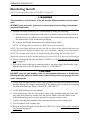
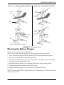
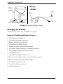
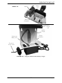
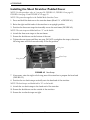
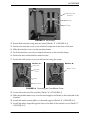
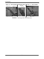
1
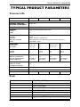
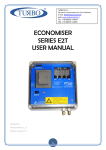
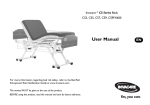
Owner’s Operator and Maintenance Manual
Invacare Continuing Care, Inc.
Traverse Lift/Transporter
1200 Series
and
1500 Series
1300 Series
and
1600 Series
DEALER: This manual MUST be given to
the user of the patient lift.
USER: BEFORE using this patient lift, read
this manual and save for future reference.
For more information regarding
Invacare Continuing Care, Inc. (ICCI) products,
parts, and services, please visit www.invacare-ccg.com
or call 800-668-2337
WARNING
DO NOT USE THIS PRODUCT OR ANY AVAILABLE OPTIONAL
EQUIPMENT WITHOUT FIRST COMPLETELY READING AND
UNDERSTANDING THESE INSTRUCTIONS AND ANY
ADDITIONAL INSTRUCTIONAL MATERIAL SUCH AS OWNER’S
MANUALS, SERVICE MANUALS OR INSTRUCTION SHEETS
SUPPLIED WITH THIS PRODUCT OR OPTIONAL EQUIPMENT. IF
YOU ARE UNABLE TO UNDERSTAND THE WARNINGS,
CAUTIONS OR INSTRUCTIONS, CONTACT A HEALTHCARE
PROFESSIONAL, DEALER OR TECHNICAL PERSONNEL BEFORE
ATTEMPTING TO USE THIS EQUIPMENT - OTHERWISE, INJURY
OR DAMAGE MAY OCCUR.
ACCESSORIES WARNING
ICCI products are specifically designed and manufactured for use in conjunction
with ICCI accessories. Accessories designed by other manufacturers have not been
tested by ICCI and are not recommended for use with ICCI products.
For further information on this product, please call the following:
Customer Service ‐ 1‐800‐668‐2337
Technical Support ‐ 1‐800‐668‐2337
Traverse Lift/Transporter
2
Part No. 1150696
TABLE OF CONTENTS
TABLE OF CONTENTS
SPECIAL NOTES ................................................................................ 5
LABEL LOCATION ............................................................................ 6
TYPICAL PRODUCT PARAMETERS .................................................... 7
Traverse Lifts...............................................................................................................................................7
Scale ...............................................................................................................................................................7
SECTION 1—GENERAL GUIDELINES ................................................... 8
Operating the Lift .......................................................................................................................................8
Lifting/Transferring .....................................................................................................................................8
Performing Maintenance ...........................................................................................................................9
Electrical - Grounding Instructions ........................................................................................................9
Pinch Points..................................................................................................................................................9
SECTION 2—OPERATING THE BATH LIFT ........................................ 10
Locking and Unlocking the Casters......................................................................................................10
Transferring into/out of the Lift............................................................................................................11
Using the Stretcher..............................................................................................................................11
Using the Seat .......................................................................................................................................11
Transferring into/out of the Tub...........................................................................................................12
Raising/Lowering the Bath Lift ...............................................................................................................13
Disinfecting the Lift ..................................................................................................................................14
Mounting the Battery Charger ..............................................................................................................15
Charging the Battery................................................................................................................................16
Using the Wall-Mounted Battery Charger.....................................................................................16
Using the On-Board Battery Charger.............................................................................................18
SECTION 3—USING THE SCALE ....................................................... 19
Removing/Installing the Bath Scale .......................................................................................................19
Functions ....................................................................................................................................................21
Replacing the Battery...............................................................................................................................22
Calibrating the 1100 Bath Scale.............................................................................................................23
SECTION 4—ADJUSTMENTS ............................................................ 24
Adjusting the Frame Column Height ...................................................................................................24
Adjusting the Lift Column.......................................................................................................................25
Part No. 1150696
3
Traverse Lift/Transporter
TABLE OF CONTENTS
TABLE OF CONTENTS
SECTION 5— MAINTENANCE AND TROUBLESHOOTING .................. 26
Safety Inspection Checklists...................................................................................................................26
Inspect/Adjust Initially and Monthly.................................................................................................26
Adjust Every 6 Months .......................................................................................................................26
Care and Maintenance of Bath Lift .......................................................................................................27
Detecting Wear and Damage ................................................................................................................27
Cleaning the Lift........................................................................................................................................27
Troubleshooting........................................................................................................................................28
Lifts ..........................................................................................................................................................28
Scale ........................................................................................................................................................28
SECTION 6—ACCESSORIES .............................................................. 29
Installing the Stretcher Cover ...............................................................................................................29
Installing the Short Stretcher Padded Cover .....................................................................................30
LIMITED WARRANTY ..................................................................... 35
Traverse Lift/Transporter
4
Part No. 1150696
SPECIAL NOTES
SPECIAL NOTES
Signal words are used in this manual and apply to hazards or unsafe practices which could result in personal injury or property damage. Refer to the table below for definitions of the signal words.
SIGNAL WORD
DANGER
MEANING
Danger indicates an imminently hazardous situation which, if not avoided, will
result in death or serious injury.
WARNING
Warning indicates a potentially hazardous situation which, if not avoided, could
result in death or serious injury.
CAUTION
Caution indicates a potentially hazardous situation which, if not avoided, may
result in property damage or minor injury or both.
NOTICE
THE INFORMATION CONTAINED IN THIS DOCUMENT IS SUBJECT TO
CHANGE WITHOUT NOTICE.
WARNING
MAINTENANCE
Maintenance MUST be performed ONLY by qualified personnel.
Part No. 1150696
5
Traverse Lift/Transporter
LABEL LOCATION
LABEL LOCATION
Serial number label is
located here
Traverse Lift/Transporter
6
Part No. 1150696
TYPICAL PRODUCT PARAMETERS
TYPICAL PRODUCT PARAMETERS
Traverse Lifts
1200 SERIES
1300 SERIES
1500 SERIES
1600 SERIES
FRAME:
Powder coated tubular steel
SUPPORT ARMS AND
RELATED ACCESSORIES:
Stainless steel
LIFT DRIVE MECHANISM:
Battery powered ball screw actuator
CASTERS
FRONT:
REAR:
Locking and steering hospital grade casters
3 in
5 in
ELECTRICAL
MOTOR:
BATTERY:
BATTERY CHARGER:
INPUT:
12V DC
12V DC, 15 amp/hr, sealed gel-cell
Wall-mounted automatic rapid charging with a rate of 2 amps per hr
115AC, 60Hz, 1.2 amp
STRETCHER
STANDARD:
N MODELS:
80.5 in x 18 in
70 in x 16 in
n/a
n/a
80.5 in x 18 in
70 in x 16 in
n/a
n/a
SEAT
WIDTH:
DEPTH:
n/a
n/a
16.5 in
16.5 in
n/a
n/a
16.5 in
16.5 in
BASE
HEIGHT (CLEARANCE):
WIDTH (OUTER/INNER):
DEPTH (MIN/MAX):
5 in
34.5 in/28.5 in
29.5 in/33 in
5 in
34.5 in/28.5 in
29.5 in/33 in
5 in
34.5 in/28.5 in
32.5 in/36 in
5 in
34.5 in/28.5 in
32.5 in/36 in
PERFORMANCE
VERTICAL TRAVEL:
COLUMN POSITIONS:
30 in
7
SHIPPING WEIGHT:
236 lbs (107 Kg)
WEIGHT LIMITATION:
350 lbs (159 Kg)
COLORS:
White
White
Grey
Grey
Scale
WEIGHT RANGE:
RESOLUTION:
DISPLAY:
AUTOMATIC POWER DOWN:
SIZE:
WEIGHT:
POWER:
BATTERY LIFE:
Part No. 1150696
Up to 350 lbs (158.7 Kg)
+/- 1 lbs (0.4 Kg)
Liquid Crystal Digital
One minute after processor displays weight data
6” H x 8” W x 7” D
25 lbs
9-Volt Alkaline battery (included)
Approximately 3000 readings
7
Traverse Lift/Transporter
GENERAL GUIDELINES
SECTION 1—GENERAL GUIDELINES
WARNING
SECTION 1 - GENERAL GUIDELINES contains important information for the safe
operation and use of this product.
Operating the Lift
Check all parts for shipping damage before using. In case of damage, DO NOT use the equipment. Contact the dealer or customer service for further instructions.
DO NOT attempt any transfer without approval of the resident’s physician, nurse or medical assistant. Thoroughly read the instructions in this owner’s manual, observe a trained team of experts perform the lifting procedures and then perform the entire lift procedure several times with proper supervision and a capable individual acting as a resident.
Use common sense in all lifts. Special care must be taken with people with disabilities who cannot fully cooperate while being transferred. Although ICCI recommends that two assistants be used for all lifting and transferring procedures, our equipment will permit proper operation by one assistant. The use of one assistant is based on the evaluation of the health care professional for each individual case.
DO NOT exceed maximum weight limitation of the lift. The weight limitation for the lift is 350 lbs.
ALWAYS keep hands and fingers clear of moving parts to avoid injury.
Lifting/Transferring
ICCI recommends the use of the safety strap and shoulder harness when using the bath lift. Always adjust the safety strap and shoulder harness for safety and comfort before transport.
During transfer, raise the seat so the resident’s feet are suspended from the floor. DO NOT roll caster base over objects such as carpet, raised carpet bindings, door frames, or any uneven surfaces or obstacles that would create an imbalance of the lift and could cause the lift to tip over. Lock the rear casters of the bath lift when transferring an individual onto the seat or stretcher. Locking the rear casters will stabilize the lift and help prevent it from shifting during transfer. Traverse Lift/Transporter
8
Part No. 1150696
GENERAL GUIDELINES
Performing Maintenance
Refer to MAINTENANCE AND TROUBLESHOOTING on page 26 for a maintenance schedule and procedures.
Regular maintenance of lifts and accessories is necessary to assure proper operation.
Casters and axle bolts require inspections every six months to check for tightness, wear, debris (such as hair and dirt) and that they roll free.
After the first twelve months of operation, inspect all glides, rollers, and fasteners for wear. Make this inspection every six months thereafter. If the metal is worn, the parts MUST be replaced.
Bearing screws on the lift column MUST be adjusted regularly. Otherwise, the lift column may seize and become inoperable. Refer to Troubleshooting on page 28.
DO NOT attempt to open the motor or obtain local service as this will VOID the warranty and may result in damage and a costly repair. Consult your dealer or ICCI for further information.
Electrical - Grounding Instructions
DO NOT, under any circumstances, cut or remove the round grounding prong from any plug. Some devices are equipped with three‐prong (grounding) plugs for protection against possible shock hazards. Where a two‐prong wall receptacle is encountered, it is the personal responsibility and obligation of the customer to contact a qualified electrician and have the two‐prong receptacle replaced with a properly grounded three‐
prong wall receptacle in accordance with the National Electrical Code. If you must use an extension cord, use only a three‐wire extension cord having the same or higher electrical rating as the device being connected. In addition, ICCI has placed RED/ORANGE WARNING TAGS on some equipment. DO NOT remove these tags. Carefully read battery/battery charger information prior to installing, servicing or operating your lift.
Pinch Points
WARNING
Pinch points exist at base of lift. Be careful, injury could occur.
Part No. 1150696
9
Traverse Lift/Transporter
OPERATING THE BATH LIFT
SECTION 2—OPERATING THE
BATH LIFT
WARNING
DO NOT attempt any transfer of a resident without approval of the resident's
physician, nurse, or medical assistant. Thoroughly read the instructions in this
owner's manual, observe a trained team of experts performing the lifting
procedures and then perform the entire lift procedure several times with proper
supervision and a capable individual acting as a resident.
ICCI recommends the use of the safety strap and shoulder harness when using the
bath lift. Always adjust the safety strap and shoulder harness for safety and comfort
before transferring the resident onto the chair.
The safety strap should be used when lifting or transferring. Otherwise, the resident
may fall from the seat.
Adjustments for safety and comfort should be made before moving the resident.
Lock the rear casters of the bath lift when transferring an individual onto the seat or
stretcher. Locking the rear casters will stabilize the lift and help prevent it from
shifting during transfer.
Each facility and each resident will require a unique set of instructions and
procedures to follow for each bath. Check with your supervisor and the resident’s
chart for the proper procedures to follow.
Review and practice the operation with an able bodied assistant before attempting
with a resident.
NOTE: ICCI recommends that two assistants be used for all lifting preparation and transferring to/
from procedures; however, the bath lift can be operated with one assistant.
Locking and Unlocking the Casters
NOTE: For this procedure, refer to FIGURE 2.1.
Lock
1. Lock the two rear locking casters on the lift by pressing down on the locking pedal with your foot.
Unlock
2. Unlock the locking casters on the lift by lifting up on the locking pedal with your foot.
Locking Pedal
Locking
Pedal
FIGURE 2.1 Locking and Unlocking the
Casters
Traverse Lift/Transporter
10
Part No. 1150696
OPERATING THE BATH LIFT
Transferring into/out of the Lift
Using the Stretcher
NOTE: For this procedure, refer to FIGURE 2.2.
NOTE: To transfer out of the lift, reverse this procedure.
Stretcher
1. Position the lift next to the bed with the stretcher parallel to the bed.
2. If necessary, unfold the stretcher by performing the following steps (Detail “A”):
Resident
A. Press and hold the button on the stretcher frame.
B. Lower the wing arm down to the desired position.
Lift
Bed
DETAIL “A”
C. Repeat steps A and B for the opposite wing arm.
Stretcher
Frame
Wing
Arm
3. Lower the stretcher to the bed height. Refer to Raising/Lowering the Bath Lift on page 13.
4. Roll the resident to the side away from the stretcher.
Button
5. Push the lift toward the resident.
NOTE: Stretcher cover not shown for clarity.
6. Lock the casters. Refer to Locking and Unlocking the Casters on page 10.
FIGURE 2.2 Transferring into/out of the
Lift - Using the Stretcher
7. Roll the resident onto the stretcher.
8. Install the side guard and straps (not shown).
NOTE: The resident position can be adjusted by raising or lowering the stretcher ends.
Using the Seat
NOTE: For this procedure, refer to FIGURE 2.3 on page 12.
NOTE: To transfer out of the lift, reverse this procedure.
1. Position the lift next to the seated resident.
2. Lower the seat to the resident’s seat height. Refer to Raising/Lowering the Bath Lift on page 13.
3. Lock the casters. Refer to Locking and Unlocking the Casters on page 10.
4. Swing one or both armrests out of the way.
Part No. 1150696
11
Traverse Lift/Transporter
OPERATING THE BATH LIFT
5. Transfer the resident onto the seat.
Lift
NOTE: Use the transfer methods prescribed by the facility and the needs of the resident.
6. Secure the resident in the seat using the straps (not shown).
Seat
7. Swing the armrests back into position.
FIGURE 2.3 Transferring into/out of the
Lift - Using the Seat
Transferring into/out of the Tub
CAUTION
The bath lift is designed for use with Sit and Supine Tubs only. The seat does not fit
into Side Entry tubs.
NOTE: For this procedure, refer to FIGURE 2.4 and FIGURE 2.5 on page 13.
NOTE: To transfer out of the tub, reverse this procedure.
1. Prepare the tub for bathing. Refer to the tub owner’s manual.
2. Transfer the resident into the lift. Refer to Transferring into/out of the Lift on page 11. 3. Position the lift seat so that the resident’s feet are off of the floor. Refer to Raising/Lowering the Bath Lift on page 13.
NOTE: Position the lift seat at a comfortable low height so that the caregiver can maintain eye contact with the resident.
NOTE: Stretcher shown.
4. Unlock the casters. Refer to Locking and Unlocking the Casters on page 10.
FIGURE 2.4 Transferring into/out of the
Tub
5. Move the resident to the bathing unit using the lift.
6. Height Adjustable Bathing Units ‐ Adjust the height of the tub to the lowest position.
7. Adjust the height of the seat or stretcher so it is slightly higher than the side of the tub.
8. Slowly begin to bring the resident over the tub.
NOTE: If using the seat, the resident’s legs may need to be placed over the side of the tub.
Traverse Lift/Transporter
12
Part No. 1150696
OPERATING THE BATH LIFT
9. Center the resident over the tub.
10. Lock the casters. Refer to Locking and Unlocking the Casters on page 10.
11. Perform one or both of the following:
• Lower the resident into the tub, making sure all parts of the stretcher or seat clear the tub edges.
• Raise the height of the height adjustable tub.
12. Bathe the resident.
13. Reverse STEPS 2 thru 11 to transfer the resident out of the tub.
14. Disinfect the lift. Refer to Disinfecting the Lift on page 14
Bathing the Resident
Centering the Resident Over the Tub
FIGURE 2.5 Transferring into/out of the Tub
Raising/Lowering the Bath Lift
NOTE: For this procedure, refer to FIGURE 2.6.
• To raise the bath lift, press the up arrow button on the hand pendant.
• To lower the bath lift, press the down arrow button on the hand pendant.
Up
Arrow
Hand
Pendant
Down
Arrow
FIGURE 2.6 Raising/Lowering the Bath Lift
Part No. 1150696
13
Traverse Lift/Transporter
OPERATING THE BATH LIFT
Disinfecting the Lift
NOTE: For this procedure, refer to FIGURE 2.7 on page 15.
WARNING
The stretcher or seat and arms of the lift must be disinfected after each use with a
bath.
ALWAYS wear protective gloves and eye protection when working concentrated
chemical disinfectants.
1. Prepare a working solution of ICCI disinfectant by doing the following:
A. Mix concentrated disinfectant with water to a dilution ration of half‐an‐ounce of disinfectant per one gallon of water. Prepare the disinfectant in accordance with the instructions on the disinfectant packaging.
B. Transfer the diluted disinfectant into a labeled spray bottle.
NOTE: The dilution label and bottle size MUST be accurate and match.
NOTE: The closed loop disinfectant system in the tub can also be used to obtain disinfectant from the burp fitting and/or disinfectant wand. Refer to the tub owner’s manual for more information.
NOTE: The stretcher cover may also be laundered using the washing machine. Refer to the laundering instructions tag for machine washing instructions. DO NOT dry using a clothes dryer.
2. Position the bath lift into the tub. Refer to STEPS 6 to 11 in Transferring into/out of the Tub on page 12.
3. Spray both sides of the seat or stretcher surface, the safety strap, the shoulder strap, and the arm rests of the lift. Refer to Detail “A” of FIGURE 2.7.
CAUTION
DO NOT spray the push handles, scale, or hand pendant with water or disinfectant.
Directly spraying water or disinfectant on these components may damage the electronic components.
4. Gently wipe the push handles, scale, hand pendant, and any other surfaces that were handled during the transport and bathing of the resident with a wash cloth containing the diluted disinfectant. Refer to Detail “B” of FIGURE 2.7.
5. Let the disinfectant sit for ten minutes.
6. After ten minutes, rinse the seat surface, safety strap, shoulder strap, arm rests, and any other non‐electronic surface with the shower wand of the bath. Refer to the individual bathing unit’s owner’s manual for using the shower wand.
7. Lightly wipe the push handles, scale, and hand pendant with a damp cloth.
8. Dry all surfaces with a clean towel.
9. Remove the bath lift from the tub. Reverse STEPS 13 to 16 in Locking and Unlocking the Casters on page 10.
Traverse Lift/Transporter
14
Part No. 1150696
OPERATING THE BATH LIFT
DETAIL “A” - NON ELECTRONIC SURFACES
DETAIL “B” - ELECTRONIC SURFACES
Scale
Push
Handle
Stretcher
Surface
Hand
Pendant
Base
Scale
Push
Handle
Hand
Pendant
Arm Rests
Base
Seat
Surface
NOTE: Safety straps not shown.
FIGURE 2.7 Disinfecting the Lift
Mounting the Battery Charger
NOTE: For this procedure, refer to FIGURE 2.8.
NOTE: Refer to state and local regulations concerning proper mounting procedures.
1. Place the battery charger mounting bracket on the wall at the desired position.
2. With a pencil, mark the mounting hole positions.
3. Install the mounting screws (not shown) until there is an approximate 1/8‐inch gap between the screw head and the wall.
4. Install the battery charger with mounting bracket onto the mounting screws.
5. Tighten the mounting screws (not shown) securely.
6. Plug the battery charger power cord into the wall electrical outlet.
NOTE: The RED and GREEN LEDs will illuminate. The illumination of the LEDs indicates that the charger is operable. Part No. 1150696
15
Traverse Lift/Transporter
OPERATING THE BATH LIFT
DETAIL “A” BATTERY
CHARGER
Battery
Charger
Mounting
Bracket
Mounting
Holes
Battery
Charger
Charger
Cord
Power
Cord
NOTE: Battery charger not shown.
FIGURE 2.8 Mounting the Battery Charger
Charging the Battery
NOTE: For this procedure, refer to FIGURE 2.9 on page 17.
Using the Wall-Mounted Battery Charger
1. Lift the battery lid (Detail “A”).
2. Disconnect the battery connectors.
3. Remove the battery from the lift.
4. Lift the lid on the battery charger.
5. Position the battery into the battery charger.
6. Connect the charger connector to the battery connector.
7. Plug the battery charger into a power outlet.
8. Charge the battery.
9. Lift the battery charger lid (Detail “A”).
10. Disconnect the charger connector from the battery connector.
11. Remove the battery from the battery charger.
12. Install the battery into the lift.
13. Connect the battery connectors.
14. Close the battery lid.
Traverse Lift/Transporter
16
Part No. 1150696
OPERATING THE BATH LIFT
DETAIL “A”
Battery
Lid
Battery
Battery
Connectors
Battery
Charger
Lid
Battery
Charger
Charger
Connector
Position the
Battery here
Plug into a
Power Outlet
FIGURE 2.9 Using the Wall-Mounted Battery Charger
Part No. 1150696
17
Traverse Lift/Transporter
OPERATING THE BATH LIFT
Using the On-Board Battery Charger
NOTE: For this procedure, refer to FIGURE 2.10.
CAUTION
If the charging cord is not locked into the battery charge port the battery will not
charge fully.
Always unplug the charging cord from the battery charge port before wheeling the
lift away. Otherwise, damage to the charging cord will occur.
1. Plug the charging cord into the battery charge port by performing the following steps:
A. Insert the charging cord into the battery charge port.
B. Rotate the charging cord to lock it into the battery charge port.
2. Press the switch to the Charge position.
3. Plug the battery charger into a power outlet.
4. Charge the battery.
5. Perform the following steps to disconnect the charging cord from the battery charge port:
A. Rotate the charging cord to unlock it from the battery charge port.
B. Remove the charging cord from the battery charge port.
6. Press the switch to the Lift position.
Charging Cord
CHARGE Position (Up)
Battery
Charger
LIFT
Position
(Down)
Switch
Battery
Charge Port
FIGURE 2.10 Using the On-Board Battery Charger
Traverse Lift/Transporter
18
Part No. 1150696
USING THE SCALE
SECTION 3—USING THE SCALE
WARNING
DO NOT attempt any transfer of a resident without approval of the resident's
physician, nurse, or medical assistant. Thoroughly read the instructions in this
owner's manual, observe a trained team of experts performing the lifting
procedures and then perform the entire lift procedure several times with proper
supervision and a capable individual acting as a resident.
ICCI recommends the use of the safety strap and shoulder harness when using the
bath lift. Always adjust the safety strap and shoulder harness for safety and comfort
before transferring the resident onto the chair.
The safety strap should be used when lifting or transferring. Otherwise, the resident
may fall from the seat.
Make adjustments for safety and comfort before moving the resident.
Lock the rear casters of the bath lift when transferring an individual onto the seat or
stretcher. Locking the rear casters will stabilize the lift and help prevent it from
shifting during transfer.
Each facility and each resident will require a unique set of instructions and
procedures to follow for each bath. Check with your supervisor and the resident’s
chart for the proper procedures to follow.
Review and practice the operation with an able bodied assistant before attempting
with a resident.
NOTE: ICCI recommends that two assistants be used for all lifting preparation and transferring to/
from procedures; however, the bath lift can be operated with one assistant. The use of one assistant is based on the evaluation of the health care professional for each individual case.
Removing/Installing the Bath Scale
NOTE: For this procedure, refer to FIGURE 3.1 on page 20.
NOTE: To install the bath scale, reverse this procedure.
1. Lock the two rear locking casters on the bath lift by pressing down on the locking pedal with your foot (Detail “A”).
2. Press on the down arrow on the hand pendant to lower the bath lift.
3. Remove the three bolts that secure the hanger rods to the bath scale (Detail “D”).
4. Pull the hanger rods away from the patient scale to remove the seat or stretcher from the bath lift.
NOTE: If the hand pendant is hanging on the steering handle (as shown in Detail “C”, remove it from the steering handle before lifting the bath scale off of the lift column.
5. Lift the bath scale off of the lift column.
Part No. 1150696
19
Traverse Lift/Transporter
USING THE SCALE
DETAIL “A”
Locking
Pedal
DETAIL “C”
1100 Bath Scale
(shown in place)
Hand Pendant
DETAIL “B”
Up
Arrow
Lift Column
NOTE: Model 1300 Bath Lift shown.
Hanger Rods
Hand
Pendant
Down
Arrow
Seat
DETAIL “D”
Hanger rods
Lift
Column
Bolts
FIGURE 3.1 Removing/Installing the Bath Scale
Traverse Lift/Transporter
20
Part No. 1150696
USING THE SCALE
Functions
CAUTION
DO NOT operate keypad with pointed objects (i.e. pencils, pens, fingernails, etc.) otherwise damage to the key pad will result.
DESCRIPTION
ZERO
LOCATION
DEFINITION
Lower Left below the Display Window Pressing this key when the scale is on will reset the
weight shown in the display window to zero.
Lower Right below the Display Window
This key is used to display the patient’s weight value
in the display window.
Note: The patient’s weight will be displayed for approximately 60 seconds.
Underneath Display Window
Use the LB/KG switch to switch between Pounds and
Kilograms
Upper Left Corner of Display
window
“B” will show in the display window to notify when
battery is low.
WEIGH
LB/KG SWITCH
LOW BATT
INDICATOR
Display
Window
Keypad
LB/KG Switch
FIGURE 3.2 1100 Bath Scale
Part No. 1150696
21
Traverse Lift/Transporter
USING THE SCALE
Replacing the Battery
NOTE: For this procedure, refer to FIGURE 3.3.
NOTE: The scale is powered by a nine volt alkaline battery that should provide approximately 3,000 readings before needing replacement.
NOTE: When battery replacement is needed, a “B” will appear in the upper left hand corner of the display window.
1. Remove the two screws that attach the battery cover to the bath scale.
2. Remove and replace the 9 Volt battery.
3. Attach the battery cover to the bath scale with two screws.
Battery Cover
9 Volt Battery
FIGURE 3.3 Replacing the Battery
Traverse Lift/Transporter
22
Part No. 1150696
USING THE SCALE
Calibrating the 1100 Bath Scale
NOTE: For this procedure, refer to FIGURE 3.1 on page 20 and FIGURE 3.4.
1. The patient MUST be removed from the bath lift to properly calibrate the bath scale. Refer to Transferring into/out of the Lift of the Bath Lift Owner’s Manual for instructions.
2. Remove the seat/stretcher from the bath lift.
• Lock the two rear locking casters.
• Press on the down arrow on the hand pendant to lower the bath lift.
• Remove the three bolts that secure the hanger rods to the bath scale.
• Pull the hanger rods away from the patient scale to remove the seat or stretcher from the bath lift.
3. Remove the four screws that attach the cover to the bath scale.
NOTE: The RUN/CAL switch is located next to the display window and is visible after the cover is removed.
4. Slide the switch marked RUN/CAL to the CAL position.
5. Adjust R9 so the display indicates +15 pound offset. Refer to Detail “A” of FIGURE 3.4.
6. Reverse STEP 2 to attach the seat or stretcher to the bath lift.
7. Make note of the weight of the seat or stretcher on the display.
8. Put 200 pounds of calibrated weight on the seat or stretcher. Check for the proper weight increase relative to the weight of the seat or stretcher noted in STEP 7.
9. Adjust R18 until the weight on the display is accurate of the combined weight of the calibrated weight and the weight of the seat or stretcher. Refer to Detail “A” of FIGURE 3.4.
10. Remove the calibrated weight from the bath scale. Repeat STEPS 5‐9 as necessary.
11. Slide the RUN/CAL switch to the RUN position. Press the ZERO button.
12. When the display window reads 0.0, place the calibrated weight on the seat or stretcher and make sure the weight on the display is correct.
13. Remove the calibrated weight from the bath scale.
NOTE: The bath scale is ready for use.
DETAIL “A” - 1100 BATH SCALE CIRCUIT BOARD
R9 Adjustment Screw
Screw
(1 of 4)
Cover
R18 Adjustment Screw
FIGURE 3.4 Calibrating the 1100 Bath Scale
Part No. 1150696
23
Traverse Lift/Transporter
ADJUSTMENTS
SECTION 4—ADJUSTMENTS
Adjusting the Frame Column Height
NOTE: For this procedure, refer to FIGURE 4.1.
If the lift seat or stretcher touch the bottom of the bathing system or are too high for the bathing system, use this procedure to ensure the frame column has been adjusted to the proper height. NOTE: The bottom of the seat or the stretcher should be approximately two inches above the bottom of the bathing system.
1. Lower the lift. Refer to Raising/Lowering the Bath Lift on page 13.
2. Lock the casters. Refer to Locking and Unlocking the Casters on page 10.
3. Stretchers Only ‐ Perform the following to fold up both ends of the stretcher:
A. Press and hold the button on the stretcher frame.
B. Fold up the end of the stretcher.
C. Repeat STEPS A and B for the other end of the stretcher.
4. Press and hold the release lever.
5. Swing the bottom of the stretcher or seat out and up.
6. Raise or lower the stretcher or seat onto one of the six column stops.
Column
Stops
Stretcher End
Stretcher Frame
Button
Stretcher
Column Stop
Release Lever
Column Stop
FIGURE 4.1 Adjusting the Frame Column Height
Traverse Lift/Transporter
24
Part No. 1150696
ADJUSTMENTS
Adjusting the Lift Column
NOTE: For this procedure, refer to FIGURE 4.2.
NOTE: The nylon bearing screws installed in the outer column have been adjusted at the factory before shipping. They keep the outer column centered around the inner column and provide a smooth glide up and down. The ends of the nylon bearing screws can wear with use and should be checked periodically. Approximately every six months, check the adjustment of the nylon bearing screws. 1. Lower the lift to the full down position.
2. Turn one of the nylon bearing screws until the screw bottoms on the inner column.
3. Back off the screw 1/8 turn.
4. Repeat for the remaining 3 nylon bearing screws.
5. Ensure the outer column looks centered on the inner column. If it is not centered, perform the following steps:
A. Loosen one nylon bearing screw.
B. Tighten the nylon bearing screw directly opposite the screw loosened in STEP A.
C. Repeat Steps A and B until the outer column is centered on the inner column.
6. If the column binds or chatters, repeat STEPS 1‐5.
Outer Column
Nylon
Bearing
Screw
Lift Base
Inner Column
FIGURE 4.2 Adjusting the Lift Column
Part No. 1150696
25
Traverse Lift/Transporter
MAINTENANCE AND TROUBLESHOOTING
SECTION 5— MAINTENANCE AND
TROUBLESHOOTING
Safety Inspection Checklists
Inspect/Adjust Initially and Monthly
❑ Inspect caster base for missing hardware.
❑ Ensure that the caster base is level and not rocking on casters.
❑ Inspect the casters and axle bolts for tightness.
❑ Inspect casters for smooth swivel and roll.
❑ Ensure that casters are free of debris.
❑ Inspect the inner mast for bends or scrapes.
❑ Inspect the arms, hardware and attachment points.
❑ Ensure the seat arms lift out to the sides.
❑ Ensure the button positions stretcher arms properly.
❑ Ensure that the seat arms are level and/or even.
❑ Ensure that the electric actuator assembly operates smoothly and quietly.
❑ Clean the lift whenever necessary. Regular cleaning will reveal loose or worn parts, enhance smooth operation and extend the life expectancy of the lift.
❑ Inspect all safety strap attachments to ensure proper connection and occupant safety.
❑ Inspect the safety strap for signs of wear. Replace if worn or damaged.
❑ Check that all labels are present and legible. Replace if necessary.
❑ Inspect electrical components for signs of corrosion. Replace if corroded or damaged.
Adjust Every 6 Months
❑ Adjust the frame column. Refer to Adjusting the Lift Column on page 25.
Traverse Lift/Transporter
26
Part No. 1150696
MAINTENANCE AND TROUBLESHOOTING
Care and Maintenance of Bath Lift
The lifts are designed to provide a maximum of safe, efficient and satisfactory service with minimum care and maintenance.
All parts of the lifts are made of the best grades of steel, but metal‐to‐metal contact will wear after considerable use.
There is no adjustment or maintenance of either the casters or wheel locks, other than cleaning, lubrication and checking axle and swivel bolts for tightness. Remove all debris, etc. from the wheel and swivel bearings. If any parts are worn, replace these parts immediately.
If you question the safety of any part of the lift, contact ICCI immediately.
Detecting Wear and Damage
It is important to inspect all stressed parts. Replace any damaged or worn parts immediately and ensure that the lift is not used until repairs are made.
Cleaning the Lift
WARNING
The arms and seat of the lift must be cleaned and disinfected after each use with a
bath. Refer to Disinfecting the Lift on page 14.
1. A soft cloth, dampened with water and a small amount of mild detergent, wipe down all parts of the lift that are submerged in water from the bath. NOTE: The lift can be cleaned with non‐abrasive cleaners or disinfectants.
CAUTION
DO NOT use the dryer when laundering the stretcher cover, button cover and
safety straps. Line dry only. Otherwise damage may occur.
2. Remove the stretcher cover, button cover and safety straps and wash in warm soapy water. Disinfect as necessary. Part No. 1150696
27
Traverse Lift/Transporter
MAINTENANCE AND TROUBLESHOOTING
Troubleshooting
NOTE: If problems are not remedied by the suggested means, please contact ICCI.
Lift
SYMPTOMS
PROBABLE CAUSE
SOLUTIONS
Seat and/or upper column feels loose.
Nylon bushing is loose.
Refer to Troubleshooting on
page 28.
Casters/brakes noisy or stiff.
Fluff or debris in bearings.
Clean the or replace the casters.
Electric actuator fails to lift when
button is pressed.
Hand-control or actuator
connector loose.
Check connections.
Battery is low.
Charge batteries. Refer to Charging
the Battery on page 16.
Battery not connected properly
to control box.
The connecting terminals are
damaged.
Electric actuator in need of
service or load is too high.
Reconnect the battery to the
control box. Refer to Charging the
Battery on page 16.
Replace the battery pack. Refer to
Charging the Battery on page 16.
Contact ICCI.
Unusual noise from actuator.
Actuator is worn or damaged or
spindle is bent.
Contact ICCI.
Scale
SYMPTOMS
Scale does NOT work properly.
PROBABLE CAUSE
Battery failure.
Battery has been replaced and
scale still does NOT work properly.
Traverse Lift/Transporter
SOLUTIONS
Check battery. Replace if necessary.
Contact ICCI.
28
Part No. 1150696
ACCESSORIES
SECTION 6—ACCESSORIES
Installing the Stretcher Cover
NOTE: For this procedure, refer to FIGURE 6.1.
DETAIL “A” - WING ARM
Stretcher
Frame
Wing Arm
NOTE: This procedure applies to the IHTRV1210 Mesh Stretcher Cover.
Button
1. Press and hold the buttons on the stretcher frame (Detail “A”).
2. Raise the right and left wing arms of the stretcher to an upright position.
DETAIL “B” - STRETCHER COVER
3. Align the stretcher cover with the stretcher frame.
4. Slide the stretcher cover down over the frame (Detail “B”).
Stretcher
Cover
NOTE: Ensure the long white straps with the male ends of the buckles are in the front of the stretcher.
Stretcher
Frame
5. Tuck the cover down under the button knobs.
6. Fasten the three white buckles to secure the stretcher cover to the stretcher frame.
Blue Strap
Buckle
White Strap
DETAIL “C” - BUTTON COVER AND
SAFETY STRAPS
7. Fasten the 2‐inch blue straps around the bottom of the stretcher frame. DO NOT overtighten the straps, otherwise the wing arms will not lower smoothly to the flat position.
8. Attach the button cover securely onto the stretcher frame using the hook and loop fasteners (Detail “C”).
Button
Cover
9. Attach the safety straps through the slots on the back of the stretcher cover (Detail “C”).
Safety Straps
FIGURE 6.1 Attaching the Stretcher Cover
Part No. 1150696
29
Traverse Lift/Transporter
ACCESSORIES
Installing the Short Stretcher Padded Cover
NOTE: For this procedure, refer to 3. on page 29, FIGURE 6.2, FIGURE 6.3 on page 31, FIGURE 6.4 on page 31 and FIGURE 6.5 on page 32.
NOTE: This procedure applies to the Padded Mesh Stretcher Cover.
1. Press and hold the buttons on the stretcher frame (Detail “A” of FIGURE 6.1).
2. Raise the right and left ends of the stretcher to an upright position.
3. Position the three seat straps horizontally across the seat frame (FIGURE 6.2).
NOTE: The seat straps are labeled with an “S” on the buckle.
4. Attach the three seat straps to the seat frame.
5. Ensure the buckles are on the bottom of the seat. 6. Tighten the seat straps until they are snug. DO NOT overtighten the straps, otherwise the wing arms will not lower smoothly to the flat position.
Wing Arm
Seat Strap
Wing Arm
Seat Frame
Buckle
FIGURE 6.2 Seat Straps
7. If necessary, raise the right or left wing arm of the stretcher to prepare the head end (FIGURE 6.3).
8. Position the two back straps vertically onto the head end of the stretcher.
NOTE: The back straps are labeled with a “B” on the buckle.
9. Attach the two back straps to the head end of the stretcher.
10. Ensure the buckles are on the outside of the stretcher.
11. Ensure the two back straps are tight.
Traverse Lift/Transporter
30
Part No. 1150696
ACCESSORIES
Head End of the
Stretcher
Buckle
Back Strap
FIGURE 6.3 Back Straps
12. Ensure both stretcher wing arms are raised (Detail “A” of FIGURE 6.4).
13. Position the stretcher cover so the white belt straps are in the front of the seat.
14. Slide the stretcher cover over the stretcher frame.
15. Tuck the stretcher cover down under the buttons on the stretcher frame.
16. Fasten the three white buckles under the seat.
17. Attach the back button cover over the buttons using the straps.
DETAIL “A”
DETAIL “B”
Wing Arm
Button Cover
Stretcher
Cover
Button
White Strap
FIGURE 6.4 Positioning the Cover/Button Cover
18. Locate the head end of the stretcher (Detail “A” of FIGURE 6.5).
19. Slide the padded mesh cover over the head support and attach to the head end of the stretcher.
20. Attach the mesh covered pillow to the head support (Detail “B” of FIGURE 6.5).
21. Attach the safety straps through the slots on the back of the stretcher cover (Detail “C” of FIGURE 6.5).
Part No. 1150696
31
Traverse Lift/Transporter
ACCESSORIES
DETAIL “A” - HEAD SUPPORT
Head Support
Head End
DETAIL “B” - MESH
PILLOW
DETAIL “C” - SAFETY STRAPS
Mesh Pillow
Padded Mesh Cover
Safety Straps
FIGURE 6.5 Head Support/Mesh Pillow/Safety Straps
Traverse Lift/Transporter
32
Part No. 1150696
ACCESSORIES
NOTES
Part No. 1150696
33
Traverse Lift/Transporter
ACCESSORIES
NOTES
Traverse Lift/Transporter
34
Part No. 1150696
LIMITED WARRANTY
LIMITED WARRANTY
PLEASE NOTE: THE WARRANTY BELOW HAS BEEN DRAFTED TO COMPLY WITH FEDERAL
LAW APPLICABLE TO PRODUCTS MANUFACTURED AFTER JULY 4, 1975.
This warranty is extended only to the original purchaser/user of our products.
This warranty gives you specific legal rights and you may also have other legal rights which vary from
state to state.
Invacare Continuing Care, Inc. (ICCI) warrants this product to be free from defects in materials and
workmanship on the lift and the electric components for a period of one year from the date of
purchase. If within such warranty period any such component shall be proven to be defective, such
component shall be repaired or replaced, at ICCI’s option. This warranty does not include any labor
or shipping charges incurred in replacement part installation or repair of any such product. ICCI’s
sole obligation and your exclusive remedy under this warranty shall be limited to such repair and/or
replacement.
For warranty service, please contact the dealer from whom you purchased your ICCI product. In the
event you do not receive satisfactory warranty service, please write directly to ICCI at the address
on the back cover, provide dealer’s name, address, date of purchase, indicate nature of the defect.
ICCI will issue a serialized return authorization. The defective unit or parts MUST be returned for
warranty inspection using the serial number, when applicable as identification within 30 days of
return authorization date. DO NOT return products to our factory without our prior consent.
C.O.D. shipments will be refused; please prepay shipping charges.
LIMITATIONS AND EXCLUSIONS: THE FOREGOING WARRANTY SHALL NOT APPLY TO
SERIAL NUMBERED PRODUCTS IF THE SERIAL NUMBER HAS BEEN REMOVED OR DEFACED,
PRODUCTS SUBJECTED TO NEGLIGENCE, ACCIDENT, IMPROPER OPERATION,
MAINTENANCE OR STORAGE, PRODUCTS MODIFIED WITHOUT ICCI’S EXPRESS WRITTEN
CONSENT (INCLUDING, BUT NOT LIMITED TO, MODIFICATION THROUGH THE USE OF
UNAUTHORIZED PARTS OR ATTACHMENTS; PRODUCTS DAMAGED BY REASON OF
REPAIRS MADE TO ANY COMPONENT WITHOUT THE SPECIFIC CONSENT OF ICCI, OR TO
A PRODUCT DAMAGED BY CIRCUMSTANCES BEYOND ICCI’S CONTROL, AND SUCH
EVALUATION WILL BE SOLELY DETERMINED BY ICCI. THE WARRANTY SHALL NOT APPLY
TO PROBLEMS ARISING FROM NORMAL WEAR OR FAILURE TO ADHERE TO THE
INSTRUCTIONS IN THIS MANUAL.
THE FOREGOING WARRANTY IS EXCLUSIVE AND IN LIEU OF ANY OTHER EXPRESS
WARRANTIES. IMPLIED WARRANTIES, IF ANY, INCLUDING THE IMPLIED WARRANTIES OF
MERCHANTABILITY AND FITNESS FOR A PARTICULAR PURPOSE, SHALL NOT EXTEND
BEYOND THE DURATION OF THE EXPRESSED WARRANTY PROVIDED HEREIN AND THE
REMEDY FOR VIOLATIONS OF ANY IMPLIED WARRANTY SHALL BE LIMITED TO REPAIR OR
REPLACEMENT OF THE DEFECTIVE PRODUCT PURSUANT TO THE TERMS CONTAINED
HEREIN. ICCI SHALL NOT BE LIABLE FOR ANY CONSEQUENTIAL OR INCIDENTAL
DAMAGES WHATSOEVER.
SOME STATES DO NOT ALLOW EXCLUSION OR LIMITATION OF INCIDENTAL OR
CONSEQUENTIAL DAMAGE, OR LIMITATION ON HOW LONG AN IMPLIED WARRANTY
LASTS, SO THE ABOVE EXCLUSIONS AND LIMITATIONS MAY NOT APPLY TO YOU.
THIS WARRANTY SHALL BE EXTENDED TO COMPLY WITH STATE OR PROVINCIAL LAWS
AND REQUIREMENTS.
Part No. 1150696
35
Traverse Lift/Transporter
www.invacare-ccg.com
USA and Canada
One Invacare Way
Elyria, Ohio USA
44036-2125
800-333-6900
Manufacturing Location
899 Cleveland Street
Elyria, Ohio USA
44036-2125
All rights reserved. Trademarks are identified
by the symbols ™ and ®. All trademarks are
owned by or licensed to Invacare
Corporation or its subsidiaries unless
otherwise noted.
©2009 Invacare Corporation
Invacare Continuing Care, Inc.
A subsidiary of Invacare Corporation.
For customer service, call 800-668-2337.
Part No. 1150696
Rev A - 01/09