1
Form P7440
Edition 10
October, 2003
CCN 04576898
Operation and Maintenance Manual
for
Series QS1L and QS1T Lever In-line Screwdrivers
Series QS1L and QS1T Lever Inline Air Screwdrivers are designed for fastening
applications in automotive and appliance assembly, the electronic and aerospace
industries and for woodworking.
•
•
•
•
IMPORTANT SAFETY INFORMATION ENCLOSED.
READ THIS MANUAL BEFORE OPERATING TOOL.
IT IS THE RESPONSIBILITY OF THE EMPLOYER TO PLACE THE
INFORMATION IN THIS MANUAL INTO THE HANDS OF THE OPERATOR.
FAILURE TO OBSERVE THE FOLLOWING WARNINGS COULD RESULT IN
INJURY
PLACING TOOL IN SERVICE
•
•
•
•
•
Always install, operate, inspect and maintain this
product in accordance with all applicable standards
and regulations (local, state, country, federal, etc.).
Always use clean, dry air at 90 psig (6.2 bar/620 kPa)
maximum air pressure at the inlet. Higher pressure
may result in hazardous situations including excessive speed, rupture, or incorrect output torque or
force.
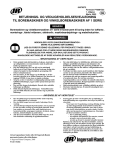
Be sure all hoses and fittings are the correct size and
are tightly secured. See Dwg. TPD905-2 for a typical
piping arrangement.
Ensure an accessible emergency shut off valve has
been installed in the air supply line, and make others
aware of its location.
Do not use damaged, frayed or deteriorated air hoses
and fittings.
•
•
•
•
•
•
Keep clear of whipping air hoses. Shut off the compressed air before approaching a whipping hose.
Always turn off the air supply, bleed the air pressure
and disconnect the air supply hose before installing,
removing or adjusting any accessory on this tool, or
before performing any maintenance on this tool or
any accessory.
Do not lubricate tools with flammable or volatile liquids such as kerosene, diesel or jet fuel. Use only recommended lubricants.
Use only proper cleaning solvents to clean parts. Use
only cleaning solvents which meet current safety and
health standards. Use cleaning solvents in a well ventilated area.
Keep work area clean, uncluttered, ventilated and
illuminated.
Do not remove any labels. Replace any damaged label.
USING THE TOOL
•
•
•
•
Always wear eye protection when operating or performing maintenance on this tool.
Always wear hearing protection when operating this
tool.
Always use Personal Protective Equipment appropriate to the tool used and material worked. This may
include dust mask or other breathing apparatus,
safety glasses, ear plugs, gloves, apron, safety shoes,
hard hat and other equipment.
When wearing gloves always be sure that the gloves
will not prevent the throttle mechanism from being
released.
Refer All Communications to the Nearest IngersollRand Office or Distributor.
© Ingersoll-Rand Company 2003
Printed in U.S.A.
•
•
•
This tool is not designed for working in explosive
environments, including those caused by fumes and
dust, or near flammable materials.
This tool is not insulated against electric shock.
Prevent exposure and breathing of harmful dust and
particles created by power tool use.
Some dust created by power sanding, sawing,
grinding, drilling and other construction activities
contains chemicals known to cause cancer, birth
defects or other reproductive harm. Some examples of these chemicals are:
- lead from lead based paints,
EN
USING THE TOOL (Continued)
•
•
•
•
•
•
•
- crystalline silica from bricks and cement and
other masonry products, and
- arsenic and chromium from chemically
treated lumber.
Your risk from these exposures varies, depending
on how often you do this type of work. To reduce
your exposure to these chemicals: work in a well
ventilated area, and work with approved safety
equipment, such as those dust masks that are specially designed to filter out microscopic particles.
Be aware of buried, hidden or other hazards in your
work environment. Do not contact or damage cords,
conduits, pipes or hoses that may contain electrical
wires, explosive gases or harmful liquids.
Keep others a safe distance from your work area, or
ensure they use appropriate Personal Protective
Equipment.
Keep hands, loose clothing, long hair and jewelry
away from working end of tool.
Power tools can vibrate in use. Vibration, repetitive
motions or uncomfortable positions may be harmful
to your hands and arms. Stop using any tool if discomfort, tingling feeling or pain occurs. Seek medical
advice before resuming use.
Keep body stance balanced and firm. Do not overreach when operating this tool. Anticipate and be
alert for sudden changes in motion, reaction torques,
or forces during start up and operation.
Tool and/or accessories may briefly continue their
motion after throttle is released.
To avoid accidental starting - ensure tool is in “off”
position before applying air pressure, avoid throttle
when carrying, and release throttle with loss of air.
•
•
•
•
•
•
•
•
•
•
•
•
•
•
•
Ensure work pieces are secure. Use clamps or vises to
hold work piece whenever possible.
Do not carry or drag the tool by the hose.
Do not use power tools when tired, or under the influence of medication, drugs, or alcohol.
Never use a damaged or malfunctioning tool or accessory.
Do not modify the tool, safety devices, or accessories.
Do not use this tool for purposes other than those recommended.
Use accessories recommended by Ingersoll-Rand.
Note the position of the reversing mechanism before
operating the tool so as to be aware of the direction of
rotation when operating the throttle.
Use only bits, sockets and adapters which are in good
condition and are intended for use with power tools
Tools supported on torque reacting balance devices
shall have these devices installed to absorb the torque
reaction of the tool.
When a suspension device is used, ensure that it is
securely fastened.
Keep clear of pinch point between reaction bar or
support handles and any fixed object in the work
area.
After repair or replacement of parts, tools with automatic shutoff or clutch devices shall be tested to verify
that the device is functioning properly.
Set the air pressure prior to setting the clutch to
desired torque. Maintain this pressure during use.
The Throttle Valve Cap is under pressure from the
Throttle Valve Spring. Use care when removing the
Throttle Valve Cap.
The use of other than genuine Ingersoll-Rand replacement parts may result in safety hazards, decreased tool
performance, and increased maintenance, and may invalidate all warranties.
Repairs should be made only by authorized trained personnel. Consult your nearest Ingersoll-Rand Authorized
Servicenter.
2
P7440 Edition 10
WARNING SYMBOL IDENTIFICATION
WARNING
This is the safety alert symbol.
It is used to alert you to potential
personal injury hazards. Obey all
safety messages that follow this
symbol to avoid possible injury
or death.
WARNING
Always wear eye protection
when operating or performing
maintenance on this tool.
WARNING
Read this manual before
operating tool.
WARNING
Always wear hearing
protection when operating
this tool.
AGENCY SYMBOL IDENTIFICATION
European Community Mark
Indicates compliance with
relevant CE directives.
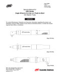
ADJUSTMENTS
CLUTCH ADJUSTMENT
3.
Disconnect the air supply from the Tool before proceeding.
opening between the faces of the Clutch Adjusting
Nut Washer and Clutch Adjusting Nut is visible.
Using a screwdriver that has a #1 Phillips tip, insert
the tip of the screwdriver into the opening and rotate
the screwdriver to adjust the Clutch. Rotate the screwdriver clockwise to decrease Clutch Spring tension
and torque and counterclockwise to increase the tension and torque.
The Clutch Adjusting Hole Cover has a left-hand thread.
Rotate the Cover clockwise to loosen or remove the Cover.
1.
2.
Unscrew the Clutch Adjusting Hole Cover far enough
to expose the clutch adjusting hole in the Clutch
Housing.
Insert a 1/4” hex wrench into the Bit Holder and
rotate the clutch mechanism until the area having an
P 7440 Edition 10
The most satisfactory adjustment is usually obtained by
using the tool on the actual application and increasing or
decreasing the delivered torque until the desired setting is
reached. In any event, it is recommended that final
adjustment be made by gradual progression.
3
LUBRICATION
We recommend the following Filter-Lubricator-Regulator
Unit:
Inside USA use FRL unit #C28-04-FKG0-28
Outside USA use FRL unit #C28-C4-FKG0
Ingersoll-Rand No. 10
Whenever the tool is disassembled for maintenance or
repair, lubricate the gear train with Ingersoll-Rand No. 67
Grease.
Gearing:
Ingersoll-Rand No. 67
Clutch:
Ingersoll-Rand No. 28
Whenever the tool is disassembled for maintenance or
repair, lubricate the clutch assembly with Ingersoll-Rand
No. 28 Grease.
Always use an air line lubricator with this tool.
INSTALLATION
Main Line(s) Inner Ø
to be 3X Size of
Air Tool's Inlet Ø
Branch Line(s) Inner Ø
to be 2X Size of
Air Tool's Inlet Ø
To Air
System
To Air
Tool
Emergency
Shut-Off
Valve
Lubricator
L
R
Regulator
F
Filter
FRL
Drain Regularly
Compressor
(Dwg. TPD905-2)
SAVE THESE INSTRUCTIONS. DO NOT DESTROY.
When the life of the tool has expired, it is recommended that the tool be disassembled, degreased and the parts be
separated by material so that they can be recycled.
4
P7440 Edition 10
P 7440 Edition 10
5
1 (Reversible)
QS (Inline)
QS
Rotation
Tool Style
1
L
L (Lever Start)
T (Lever Permit)
Throttle
20
28 (2800)
20 (2000)
17 (1710)
10 (1000)
05 (0500)
02 (0250)
Free Speed
Bit Holder or Driver
S
1
D
S (Automatic Shut-off) 1 (1/4” Quick Release)
C (Cushion Clutch)
3 (1/4” Bit Finder)
D (Direct Drive:
5 (5 mm Double End
Lever Start only)
Quick Release)
7 (1/4” Double End
Quick Release)
Clutch
MODEL IDENTIFICATION
D (Memory Chip)
B (1/4-19 BSPT Inlet)
Accessory
Manuel P7440
Révision 10
Octobre, 2003
CCN 04576898
MANUEL D’EXPLOITATION ET D’ENTRETIEN DES VISSEUSES
DROITES: SERIES QS1L ET QS1T
Les visseuses pneumatiques droites des Séries QS1L et QS1T sont destinées au serrage
des fixations : d’assemblage automobile, d’équipements ménagers, d’industries
électroniques et aérospatiales du travail du bois.
•
•
•
•
D’IMPORTANTES INFORMATIONS DE SECURITÉ SONT JOINTES.
LIRE CE MANUEL AVANT D’UTILISER L’OUTIL.
L’EMPLOYEUR EST TENU À COMMUNIQUER LES INFORMATIONS DE CE
MANUEL AUX EMPLOYÉS UTILISANT CET OUTIL.
LE NON RESPECT DES AVERTISSEMENTS SUIVANTS PEUT CAUSER DES
BLESSURES.
MISE EN SERVICE DE L’OUTIL
•
•
•
•
•
•
Installez, exploitez, inspectez et entretenez toujours
ce produit conformément à toutes les normes et réglementations (locales, départementales, nationales,
fédérales, etc.) en vigueur.
Utilisez toujours de l'air sec et propre à une pression
maximum de 90 psig (6,2 bar, 620kPa). Toute pression supérieure peut créer des situations dangereuses
y compris une vitesse excessive, une rupture ou un
couple ou effort de sortie incorrect.
S'assurer que tous les flexibles et les raccords sont
correctement dimensionnés et bien serrés. Voir Plan
TPD905-2 pour un exemble type d'agencement des
tuyauteries.
Vérifiez qu'un robinet d'arrêt d'urgence accessible a
bien été installé dans le circuit d'alimentation d'air et
notifier son emplacement à tout le personnel.
Ne pas utiliser des flexibles ou des raccords endommagés effilochés ou détériorés.
En cas de rupture ou d'éclatement du flexible d'air ne
pas s'approcher. Couper le réseau d'air comprimé
avant d'approcher du flexible d'air.
•
•
•
•
•
Coupez toujours l’alimentation d’air comprimé,
purgez la pression d’air et débranchez le flexible d’alimentation avant d’installer, déposer ou ajuster tout
accessoire sur cet outil, ou d’entreprendre une opération d’entretien quelconque sur l’outil.
Ne lubrifiez jamais les outils avec des liquides inflammables ou volatiles tels que le kérosène, le gasoil ou le
carburant d'aviation. Utilisez seulement les lubrifiants recommandés.
N’utilisez que des solvants de nettoyage appropriés
pour nettoyer les pièces. Utilisez seulement les solvants répondant aux réglementations de santé et de
sécurité en vigeur. Utilisez les solvants de nettoyage
dans une zone adaptée.
Maintenez le lieu de travail propre, sans obstruction,
aéré et bien éclairé.
Ne retirer aucune étiquette. Remplacer toute étiquette
endommagée.
UTILISATION DE L’OUTIL
•
•
•
Porter toujours des lunettes de protection pendant
l'utilisation et l'entretien de cet outil.
Porter toujours une protection acoustique pendant
l'utilisation de cet outil.
Portez toujours les équipements de protection personnelle adaptés à l'outil utilisé et au matériau travaillé.
Ces équipements peuvent être des masques antipoussière ou autre appareil respiratoire, des lunettes
de sécurité, des bouchons d'oreille, des gants, un
•
•
•
tablier, des chaussures de sécurité, un casque et
d'autres équipements.
Si vous portez des gants, vérifiez toujours que les
gants ne vous empêcheront pas de relâcher le mécanisme de commande.
Cet outil n'est pas conçu pour fonctionner dans des
atmosphères explosives, y compris celles créées par
les vapeurs ou les poussières ou près de matériaux
inflammables.
Cet outil n'est pas isolé contre les chocs électriques.
Adressez toutes vos communications au Bureau Ingersoll-Rand
ou distributeur le plus proche.
© Ingersoll-Rand Company 2003
Imprimé aux U.S.A.
6
P7440 Edition 10
FR
UTILISATION DE L’OUTIL (Continué)
•
•
•
•
•
•
•
Evitez toute exposition et respiration des poussières
et particules nocives créées par l'emploi de l'outil
pneumatique:
Certaines poussières produites par les opérations
de ponçage, sciage, meulage, perçage et autres
activités de construction contiennent des produits
chimiques qui sont reconnus comme pouvant
causer le cancer, des infirmités de naissance ou
d'autres risques à effets nocifs. Parmi ces produits
chimiques on trouve:
- le plomb des peintures à base de plomb,
- les cristaux de silice contenus dans les briques, le
ciment et d'autres produits de maçonnerie, et
- l'arsenic et le chrome des bois traités chimiquement.
Le risque présenté par l'exposition à ces poussières
est fonction de la fréquence et du type de travail
effectué. Pour réduire l'exposition à ces produits
chimiques : travaillez dans une zone bien aérée, et
utilisez les équipements de sécurité approuvés, tels
que les masques à poussière qui sont spécialement
conçus pour filtrer et arrêter les particules
microscopiques.
Soyez conscient des risques, cachés ou autres dans
votre environnement de travail. N'entrez jamais en
contact avec les câbles, les conduites, les tuyaux ou les
flexibles qui pourraient contenir des câbles électriques, des gaz explosifs ou des liquides dangereux.
Tenez les gens à une distance sûre de la zone de travail ou vérifiez qu'ils utilisent des équipements de
protection personnelle appropriés.
Gardez les mains, vêtements amples, cheveux longs et
bijoux éloignés de l'extrémité rotative de l'outil.
Les outils électriques peuvent vibrer pendant l'usage.
Les vibrations, les mouvements répétitifs et les positions inconfortables peuvent causer des douleurs
dans les mains et les bras. Cessez d'utiliser les outils
en cas d'inconfort, de picotements ou de douleurs.
Consultez un médecin avant de recommencer à utiliser l'outil.
Garder une position équilibrée et ferme. Ne pas se
pencher trop en avant pendant l'utilisation de cet
outil. Anticiper et prendre garde aux changements
soudains de mouvement, couples de réaction ou forces
lors du démarrage et de l'exploitation.
L'outil et/ou les accessoires peuvent continuer à
tourner brièvement après le relâchement de la
gâchette.
•
•
•
•
•
•
•
•
•
•
•
•
•
•
•
•
Pour éviter toute mise en marche accidentelle - vérifiez que l'outil est à la position "arrêt" avant d'appliquer l'air comprimé, évitez de toucher la commande
de mise en marche lorsque vous transportez l'outil et
relâcher la commande lorsque la pression d'air chute.
Vérifiez que les pièces à travailler sont fermement
fixées. Utilisez des brides ou un étau pour retenir les
pièces lorsque possible.
Ne transportez pas l'outil par son flexible d'air comprimé.
N'utilisez pas d'outils lorsque vous êtes fatigué ou
sous l'influence de médicaments, de drogues ou
d'alcool.
N'utilisez jamais un outil ou accessoire endommagé
ou de fonctionnement douteux.
Ne modifiez jamais l'outil, les dispositifs de sécurité
ou les accessoires.
N'utilisez pas cet outil à des fins autres que celles
recommandées.
Utiliser les accessoires recommandés par IngersollRand.
Notez la position du mécanisme d'inversion avant de
mettre l'outil en marche de manière à savoir dans
quel sens il va tourner lorsque la commande est
actionnée.
Utilisez seulement des embouts, douilles et
adaptateur en bon état et destinés aux outils pneumatiques.
Les dispositifs d'équilibrage réagissant au couple
supportant des outils doivent être installés de
manière à absorber le couple de réaction de l'outil.
Lorsqu'un dispositif de suspension est employé, vérifier qu'il est fermement attaché.
Ne vous approchez pas du point de pincement entre la
barre de réaction ou les poignées de support et tout
autre objet fixe se trouvant dans la zone de travail.
Après réparation ou remplacement de pièces, les outils équipés d'arrêt automatique ou de limiteurs
doivent être testés pour vérifier que le dispositif fonctionne correctement.
Réglez la pression d'air avant de régler le limiteur au
couple désiré. Maintenez cette pression pendant
toute l'utilisation.
Le chapeau de la soupape de commande est soumis à
la pression du ressort de soupape. Prenez les soins
nécessaires lors de la dépose du chapeau de soupape
de commande.
L'utilisation de rechanges autres que les pièces d'origine Ingersoll-Rand peut causer des risques d'insécurité, réduire les
performances de l'outil et augmenter l'entretien, et peut annuler toutes les garanties.
Les réparations ne doivent être effectuées que par des réparateurs qualifiés autorisés. Consultez votre Centre de Service
Ingersoll-Rand le plus proche.
P 7440 Edition 10
7
SIGNIFICATION DES SYMBOLES D’AVERTISSEMENT
ATTENTION
ATTENTION
C'est le symbole d'alerte de sécurité. Il est utilisé pour vous avertir
des risques possibles de blessure.
Observez tous les messages de
sécurité suivant cesymbole pour
éviter toute blessure ou la mort.
Porter toujours des lunettes
de protection pendant
l'utilisation et l'entretien de
cet outil.
ATTENTION
Lire ce manuel avant
d'utiliser l'outil.
ATTENTION
Porter toujours une
protection acoustique
pendant l'utilisation de cet
outil.
SIGNIFICATION DES SYMBOLES D’AGENCY
Marque de la Communauté
européenne
Indique la conformité
aux directives CE
appropriées.
RÉGLAGES
REGLAGE DU LIMITEUR
Débrancher l’alimentation d’air comprimé de l’outil avant
d’entreprendre les opérations suivantes.
Le capuchon du trou de réglage du limiteur est fileté à
gauche. Tourner le capuchon dans le sens horaire pour
desserrer ou déposer le couvercle.
1.
2.
8
Dévisser suffisamment la bague pour accéder au trou
de réglage du limiteur.
Insérer une clé hexagonale de 1/4” dans le porteembout et tourner le mécanisme du limiteur jusqu’à
ce que la zone ayant une ouverture entre les faces de
la rondelle et de l’écrou de réglage du limiteur soit visible.
3.
A l’aide d’un tournevis Phillips No.1, insérer la lame
du tournevis dans l’ouverture et tourner le tournevis
pour régler le limiteur. Tourner le tournevis dans le
sens horaire pour réduire la tension du ressort du limiteur et le couple, et dans le sens antihoraire pour augmenter la tension et le couple.
La meilleure méthode de réglage est normalement obtenue
en utilisant l’outil sur l’application requise en augmentant
ou en diminuant le couple fourni jusqu’à ce que le réglage
désiré soit obtenu. De plus, il est toujours recommandé
d’obtenir le réglage final au moyen de réglages progressifs.
P7440 Edition 10
LUBRIFICATION
Ingersoll-Rand No. 10
Utiliser toujours un lubrificateur avec ces outils. Nous
recommandons l’emploi du filtre-régulateur-lubrificateur
suivant:
Aux Etats-Unis, utiliser FRL #C28-04-FKG0-28
En dehors des Etats-Unis, utiliser FRL #C28-C4-FKG0
Pignonnerie:
Ingersoll-Rand No. 67
Limiteur:
Ingersoll-Rand No. 28
Lubrifier le train d’engrenages avec de la graisse IngersollRand No. 67 à chaque fois que l’outil est démonté pour
entretien ou réparation.
Lubrifier l’ensemble de limiteur avec de la graisse
Ingersoll-Rand No. 28 à chaque fois que l’outil est
démonté pour entretien ou réparation.
INSTALLATION
LIGNE SECONDAIRE AU
MOINS 2 FOIS LA DIMENSION
DE L'ADMISSION D'AIR DE
L'OUTIL
TUYAUTERIE PRINCIPALE AU
MOINS 3 FOIS LA DIMENSION
DE L'ADMISSION D'AIR DE
L'OUTIL
VERS LE
RÉSEAU
D'AIR
COMPRIMÉ
VERS L'OUTIL
PNEU-MATIQUE
L
R
ROBINET D'ARRÊT
D'URGENCE
LUBRIFICATEUR
RÉGULATEUR
VIDANGER
RÉGULIÈREMENT
F
FILTRE
FRL
COMPRESSEUR
(Dwg. TPD905-2)
CONSERVEZ SOIGNEUSEMENT CES INSTRUCTIONS. NE PAS LES DÉTRUIRE.
A la fin de sa durée de vie, il est recommandé de démonter l’outil, de dégraisser les pièces et de les séparer en fonction des
matériaux de manière à ce que ces derniers puissent être recyclés.
P 7440 Edition 10
9
10
P7440 Edition 10
1 (Réversible)
QS (En ligne)
QS
Rotation
Style d’outil
Vitesse à vide
1
L
20
L (Démarrage par gâchette) 28 (2800)
T (Gâchette de sécurité)
20 (2000)
17 (1710)
10 (1000)
05 (0500)
02 (0250)
Commande
S
1
S (Arrêt automatique)
C (Limiteur amortisseur)
D (Entraînement direct;
démarrage par gâchette
uniquement)
Limiteur
D
1 (1/4” Changement rapide) D (Puce mémoire)
3 (1/4” Coiffe d’embout)
B (1/4-19 BSPT
5 (5 mm Double extrémité
Tuyau d’entrée)
Changement rapide)
7 (1/4” Double extrémité
Changement rapide)
Porte-embout ou entraîneur Accessoire
IDENTIFICATION DES MODÈLES
Impresso P7440
Edición 10
Octubre, 2003
CCN 04576898
ES
MANUAL DE USO Y MANTENIMIENTO DE LOS ATORNILLADORES
RECTOS DE PALANCA DE LAS SERIES QS1L Y QS1T
Los atornilladores neumáticos rectos de palanca de las series QS1L y QS1T están
diseñados para aplicaciones de montaje en la industria de electrodomésticos, del
automóvil, electrónica y aeroespacial, así como para carpintería.
•
•
•
•
SE ADJUNTA INFORMACION IMPORTANTE DE SEGURIDAD.
LEA ESTE MANUAL ANTES DE USAR LA HERRAMIENTA.
ES RESPONSABILIDAD DE LA EMPRESA ASEGURARSE DE QUE EL
OPERARIO ESTE AL TANTO DE LA INFORMACION QUE CONTIENE ESTE
MANUAL.
EL HACER CASO OMISO DE LOS AVISOS SIGUIENTES PODRIA
OCASIONAR LESIONES.
PARA PONER LA HERRAMIENTA EN SERVICIO
•
•
•
•
•
•
Instale, utilice, inspeccione y mantenga siempre este
aparato de acuerdo con todas las normas locales y
nacionales que sean de aplicación.
Use siempre aire limpio y seco a una presión máxima
de 90 psig (6,2 bar/620 kPa) en la admisión. Una
presión superior puede redundar en situaciones peligrosas, entre ellas una velocidad excesiva, rotura, o
un par o una fuerza de salida incorrectos.
Asegúrese de que todas las mangueras y accesorios
sean del tamaño correcto y estén bien apretados. Vea
Esq. TPD905-2 para un típico arreglo de tuberías.
Cerciórese de que se haya instalado una válvula de
corte de emergencia en la línea de suministro de aire
y notifique a los demás de su ubicación.
No utilizar mangueras de aire y accesorios dañados,
desgastados ni deteriorados.
Manténgase apartado de toda manguera de aire que
esté dando latigazos. Apague el compresor de aire
antes de acercarse a una manguera de aire que esté
dando latigazos.
•
•
•
•
•
Corte siempre el suministro de aire, descargue la
presión de aire y desconecte la manguera de suministro de aire antes de instalar, desmontar o ajustar
cualquier accesorio de esta herramienta, o antes de
realizar cualquier operación de mantenimiento de la
misma o de un accesorio.
No lubrique las herramientas con líquidos inflamables o volátiles tales como queroseno, gasoil o combustible para motores a reacción. Use únicamente los
lubricantes recomendados.
Use solamente los disolventes apropiados para la
limpieza de las piezas. Use solamente los disolventes
de limpieza que cumplan las normas vigentes de
salud y seguridad. Los disolventes de limpieza se
deben usar en una zona bien ventilada.
Mantenga la zona de trabajo limpis, despejada, ventilada e iluminada.
No saque ninguna etiqueta. Sustituya toda etiqueta
dañada.
UTILIZACIÓN DE LA HERRAMIENTA
•
•
•
Use siempre protección ocular cuando maneje, o realice operaciones de mantenimiento en esta herramienta.
Use siempre protección para los oídos cuando maneje
esta herramienta.
Utilice siempre el equipo de protección individual que
corresponda a la herramienta en uso y al material con
el que se trabaja. Ello puede incluir una mascarilla
contra el polvo u otro aparato de respiración, gafas de
Envie Todos os Comunicados Para o Distribuidor ou Escritório
da Ingersoll-Rand Mais Próximo.
© Ingersoll-Rand Company 2003
Impresso nos E.U.A.
P 7440 Edition 10
•
•
•
seguridad, tapones de oído, guantes, delantal, zapatos
de seguridad, casco y otros artículos.
Cuando use guantes, asegúrese siempre de que estos
no eviten que se suelte el mecanismo de mando.
Esta herramienta no está diseñada para su utilización en ambientes explosivos, incluidos los que son
provocados por la presencia de vapores y polvo, o
cerca de materiales inflamables.
Esta herramienta no está aislada contra descargas
eléctricas.
11
UTILIZACIÓN DE LA HERRAMIENTA (Continuado)
•
•
•
•
•
•
•
Evite respirar el polvo y partículas nocivos que se producen al utilizar la herramienta, así como exponerse
a ellos:
Ciertos tipos de polvo que se producen al lijar, serruchar, rectificar o taladrar y durante otras actividades de la construcción contienen sustancias
químicas que son conocidos como causantes de
cáncer, defectos de nacimiento y otros daños reproductivos. Algunos ejemplos de estas sustancias
químicas:
- el plomo de las pinturas con base de plomo,
- la sílice cristalina de ladrillos y hor migón y otros
productos asociados con la albañilería, y
- el arsénico y el cromo que produce la madera
sometida a tratamientos químicos.
El riesgo a la persona que presenta una exposición
de ste tipo varia en función de la frecuencia con que
se realiza esta clase de trabajo. Para reducir la
exposición a estas sustancias químicas: trabaje en
una zona bien ventilada y utilice equipo de protección homologado, por ejemplo una mascarilla especialmente diseñada para filtrar partículas
microscópicas.
Tenga en cuenta los peligros enterrados, ocultos o de
otro tipo en el entorno de trabajo. Tenga cuidado de
no hacer contacto con, ni dañar, cables, conductos,
tuberías ni mangueras que puedan contener hilos
eléctricos, gases explosivos o líquidos nocivos.
Mantenga a los demás a una distancia segura de la
zona de trabajo, o asegúrese de que utilicen el correspondiente equipo de protección individual.
Mantenga las manos, la ropa suelta, el cabello largo y
las alhajas apartados del extremo de trabajo de la
herramienta.
Las herramientas eléctricas pueden vibrar durante el
uso. La vibración, los movimientos repetitivos o las
posiciones incómodas pueden dañarle los brazos y
manos. En caso de incomodidad, sensación de hormigueo o dolor, deje de usar la herramienta. Consulte
con el médico antes de volver a utilizarla.
Mantenga una postura del cuerpo equilibrada y
firme. No estire demasiado los brazos al manejar la
herramienta. Anticipe y esté atento a los cambios
repentinos en el movimiento, pares de reacción u
otras fuerzas durante la puesta en marcha y utilización.
El movimiento de la herramienta y/o los accesorios
puede prolongarse brevemente después de soltarse el
mando.
•
•
•
•
•
•
•
•
•
•
•
•
•
•
•
•
Para evitar el arranque imprevisto de la herramienta,
verifique que esté en la posición de desconexión "off"
antes de aplicarle aire a presión, evite tocar el mando
al transportarla y suelte el mando mientras se descarga el aire.
Asegúrese de que las piezas a trabajar estén bien
sujetas. Siempre que sea posible, utilice mordazas o
un tornillo de banco para sostener la pieza.
No lleve ni arrastre la herramienta sujetándola por la
manguera.
No utilice herramientas eléctricas cuando esté cansado o bajo la influencia de medicamentos, drogas o
alcohol.
No utilice nunca una herramienta o un accesorio
dañado o que no funcione correctamente.
No modifique la herramienta, los dispositivos de seguridad ni los accesorios.
No utilice esta herramienta para otros fines que no
sean los recomendados.
Utilice únicamente los accesorios Ingersoll-Rand
recomendados.
Tome nota de la posición del mecanismo inversor
antes de hacer funcionar la herramienta para tener
en cuenta el sentido de rotación al accionar el mando.
Utilice únicamente puntas, bocas y adaptadores que
estén en buen estado y estén previstos para uso con
herramientas eléctricas.
Las herramientas apoyadas en dispositivos equilibradores de reacción de par tendrán estos dispositivos
instalados para absorber la reacción de par de la herramienta.
Cuando se utilice un dispositivo de suspensión, verifique que esté bien asegurado.
Manténgase apartado de los puntos donde pueda pillarse los dedos entre la barra de reacción o las
empuñaduras auxiliares y cualquier objeto fijo que
haya en la zona de trabajo.
Tras reparar o sustituir piezas, las herramientas dotadas de corte automático o dispositivos de embrague
se deberán someter a prueba para verificar que el dispositivo funcione correctamente.
Ajuste la presión del aire antes de ajustar el embrague
al par deseado. Mantenga esta presión durante el uso.
El muelle de la válvula reguladora hace fuerza contra
la tapa de dicha válvula. Tenga cuidado al sacar la
tapa de la válvula.
El uso de piezas de recambio que no sean las auténticas piezas Ingersoll-Rand podría poner en peligro la seguridad,
reducir el rendimiento de la herramienta y aumentar los cuidados de mantenimiento necesarios, así como invalidar toda
garantía.
Las reparaciones sólo serán realizadas por personal cualificado y autorizado.Consulte con el centro de servicio IngersollRand autorizado más próximo.
12
P7440 Edition 10
IDENTIFICACIÓN DE SÍMBOLOS DE AVISO
ADVERTENCIA
ADVERTENCIA
Este es el símbolo de alerta de seguridad. Sirve para avisar al usuario
de posibles riesgos de lesionarse.
Acate todo mensaje de seguridad
que siga a este símbolo a fin de
evitar la posibilidad de lesiones,
que pueden llegar a ser mortales.
Use siempre protección ocular
cuando utilice esta herramienta
o realice operaciones de
mantenimiento en la misma.
ADVERTENCIA
Lea este manual antes de
usar la herramienta.
ADVERTENCIA
Use siempre protección
para los oídos cuando
utilice esta herramienta.
IDENTIFICACIÓN DE SíMBOLOS EMPLEADOS
Marca de la Comunidad Europea
Indica el cumplimiento
de las directivas
pertinentes de la CE.
AJUSTES
AJUSTE DE EMBRAGUE
Desconecte el suministro de aire comprimido de la
herramienta antes de proceder.
La tapa del orificio para ajuste del embrague tiene rosca
hacia la izquierda. Gire la tapa hacia la derecha para
aflojar o quitarla.
1. Desenrosque la tapa del orificio para ajuste del
embrague lo suficiente para que quede expuesto el
orificio en la carcasa del embrague.
2. Introduzca una llave exagonal de 1/4” en el portapuntas y gire el mecanismo del embrague hasta que quede
P 7440 Edition 10
3.
visible la zona que tiene una abertura entre las caras
de la arandela de la tuerca de ajuste del embrague y
de dicha tuerca.
Introduzca la punta de un atornillador con punta Phillips nº 1 en la abertura y gire el atornillador para
ajustar el embrague. Gire el atornillador hacia la derecha para reducir la tensión y el par del muelle del
embrague o hacia la izquierda para aumentarlos.
Normalmente se obtendrá el mejor ajuste usando la
herramienta en trabajo actual e incrementando o
disminuyendo el par hasta lograr el ajuste deseado. En
cualquier caso, se recomienda hacer el ajuste final por
progresión gradual.
13
LUBRICACION
Inside USA use FRL unit #C28-04-FKG0-28
Outside USA use FRL unit #C28-C4-FKG0
Ingersoll-Rand No. 10
Engranajes- :
Ingersoll-Rand No. 67
Embrague :
Ingersoll-Rand No. 28
Cada vez que se desarme la herramienta para realizarle
trabajos de mantenimiento o reparación, lubrique el tren
de engranajes con grasa Ingersoll-Rand Nº 67.
Cada vez que se desarme la herramienta para realizarle
trabajos de mantenimiento o reparación, lubrique el
conjunto del embrague con grasa Ingersoll-Rand Nº 28
Utilice siempre un lubricador de aire comprimido con
estas llaves de impacto. Recomendamos la siguiente
unidad de Filtro-Lubricador-Regulador:
INSTALACIÓN
TUBERÍA DE RAMAL 2 VECES
EL TAMAÑO DE ENTRADA
DE HERRAMIENTA NEUMÁTICA
TUBERÍAS PRINCIPALES
3 VECES EL TAMAÑO
DE ENTRADA DE
HERRAMIENTA NEUMÁTICA
AL SISTEMA
NEUMÁTICO
A LA HERRAMIENTA
NEUMÁTICA
VÁLVULA DE
CORTE DE
EMERGENCIA
LUBRICADOR
L
REGULADOR
PURGAR
PERIÓDICAMENTE
R
F
FILTRO
FRL
COMPRESOR
(Dwg. TPD905-2)
GUARDE ESTAS INSTRUCCIONES. NO DESTRUYA.
Una vez vencida la vida útil de herramienta, se recomienda desarmar la herramienta, desengrasarla y separar las piezas
de acuerdo con el material del que están fabricadas para reciclarlas.
14
P7440 Edition 10
P 7440 Edition 10
15
1 (reversible)
QS (recto)
QS
Rotación
Estilo de herramienta
Velocidad en
vacío
1
L
20
L (Arranque por palanca)
T (Funcionamiento por palanca) 28 (2800)
20 (2000)
17 (1710)
10 (1000)
05 (0500)
02 (0250)
Palanca de mando
S
1
S (parada automática)
C (embrague ajustable)
D (Mando directo;
arranque por palanca
solamente)
Embrague
Accesorio eléctrico
D
D (chip de memoria)
1 (1/4” de cambio rápido)
3 (localizador de brocas de 1/4”) B (1/4-19 BSPT
Boca)
5 (punta doble de 5 mm
de cambiorápido)
7 (punta doble de 1/4”de
cambio rápido)
Portapuntas o cuadradrillo
IDENTIFICACIÓN DE MODELOS
Formulário P7440
Edição 10
Outubro, 2003
CCN 04576898
MANUAL DE FUNCIONAMENTO E MANUTENÇÃO
PARA AS APARAFUSADORAS EM LINHA DE ALAVANCA DAS
SÉRIES QS1L E QS1T
As Aparafusadoras em Linha de Alavanca das Séries QS1L e QS1T são concebidas para
aplicações de fixação na montagem de automóveis e aparelhos, nas indústrias
electrónica e aeroespacial e em carpintaria.
•
•
•
•
INFORMAÇÃO DE SEGURANÇA IMPORTANTE EM ANEXO.
LEIA ESTE MANUAL ANTES DE OPERAR A FERRAMENTA.
É DA RESPONSABILIDADE DO EMPREGADOR COLOCAR A INFORMAÇÃO
DESTE MANUAL NAS MÃOS DO OPERADOR.
O NÃO CUMPRIMENTO DAS SEGUINTES ADVERTÊNCIAS PODE
RESULTAR EM FERIMENTOS.
COLOCANDO A FERRAMENTA EM FUNCIONAMENTO
•
•
•
•
•
•
Instale, opere, inspeccione e faça manutenção neste
produto sempre de acordo com todas as normas e regulamentos aplicáveis (locais, estatais, federais, nacionais etc.).
Utilize sempre ar limpo e seco a uma pressão máxima
de 6,2 bar na admissão. Pressão mais alta pode resultar
em situações perigosas incluindo velocidade excessiva,
ruptura ou binário ou força de saída incorrectos.
Certifique-se de que todas as mangueiras e acessórios
são da dimensão correcta e que estão seguros firmemente. Consulte o Des. TPD905-2 para uma disposição de tubos típica.
Certifique-se de que foi instalada uma válvula de isolamento de emergência acessível na linha de alimentação de ar e informe os outros sobre a sua
localização.
Não utilize mangueiras de ar e acessórios danificados, puídos ou deteriorados.
Mantenha-se afastado de mangueiras de ar a chicotear. Desligue o compressor antes de se aproximar
de uma mangueira de ar a chicotear.
•
•
•
•
•
Desligue sempre a alimentação de ar, liberte a
pressão do ar e desligue a mangueira de alimentação
de ar antes de instalar, retirar ou ajustar qualquer
acessório desta ferramenta, ou antes de realizar
qualquer tipo de manutenção nesta ferramenta ou em
qualquer acessório.
Não lubrifique a ferramenta com líquidos inflamáveis
ou voláteis como querosene, gasóleo ou combustível
para jactos. Utilize apenas os lubrificantes especificados.
Utilize apenas solventes de limpeza adequados para
limpar as peças. Utilize apenas solventes de limpeza
que obedeçam às normas correntes de saúde e segurança no trabalho. Utilize solventes numa área bem
ventilada.
Mantenha a área de trabalho limpa, em ordem, ventilada e bem iluminada.
Não retire nenhum rótulo. Substitua os rótulos danificados.
USANDO A FERRAMENTA
•
•
•
Use sempre protecção para os olhos ao operar ou
fazer manutenção nesta ferramenta.
Use sempre protecção auricular ao operar esta ferramenta.
Utilize sempre equipamento de protecção pessoal
apropriado para a ferramenta utilizada e o material
de trabalho. Isso pode incluir máscara contra a poeira ou outro aparelho de respiração, óculos de segurança, auriculares, luvas, avental, calçado de
segurança, capacete e outro equipamento.
•
•
Quando usar luvas, certifique-se de que as mesmas não
impedirão a libertação do mecanismo do regulador.
Evite expor-se e respirar as poeiras e partículas nocivas
criadas pela utilização de ferramentas motorizadas:
Algumas poeiras criadas por operações motorizadas de lixar, serrar, rectificar, perfurar e outras actividades de construção contêm produtos
químicos conhecidos por causarem cancro, malformações congénitas e terem efeitos nocivos na
reprodução. Alguns exemplos desses produtos
químicos são:
Envie Todos os Comunicados Para o Distribuidor ou Escritório
da Ingersoll-Rand Mais Próximo.
© Ingersoll-Rand Company 2003
Impresso nos E.U.A.
16
P7440 Edition 10
PT
USANDO A FERRAMENTA (Continuado)
•
•
•
•
•
•
•
•
•
- chumbo de tintas à base de chumbo,
- sílica cristalina de tijolos e cimento e outros
produtos de alvenaria e
- arsénico e crómio de madeira tratada quimicamente
Os riscos dessas exposições varia, dependendo
de com que frequência faz esse tipo de trabalho.
Para reduzir a sua exposição a esses produtos
químicos: trabalhe numa área bem ventilada e
com equipamento de segurança aprovado, como
as máscaras contra a poeira que são especialmente projectadas para filtrar partículas
microscópicas.
Mantenha terceiros a uma distância segura da sua
área de trabalho ou certifique-se de que os mesmos
estão a usar equipamento de protecção pessoal.
Esta ferramenta não é concebida para trabalhar em
ambientes explosivos, incluindo os provocados por
vapores e poeira ou perto de materiais inflamáveis.
Esta ferramenta não é isolada contra choque eléctrico.
Tenha em conta a possível presença de perigos enterrados, ocultos e outros no seu ambiente de trabalho.
Não contacte ou danifique cabos, condutas, tubos ou
mangueiras que possam conter fios eléctricos, gases
explosivos ou líquidos perigosos.
Mantenha as mãos, roupas soltas, cabelos longos e
jóias afastados da extremidade de trabalho da ferramenta.
As ferramentas mecânicas podem vibrar durante a utilização. Vibração, movimentos repetitivos ou posições
desconfortáveis podem ser nocivos às suas mãos e
braços. Pare de utilizar qualquer ferramenta se sentir
desconforto, sensação de formigueiro ou dor. Procure
assistência médica antes de reiniciar a utilização.
Mantenha o corpo numa posição equilibrada e firme.
Não estique o corpo ao operar esta ferramenta. Esteja
preparado e alerta para mudanças súbitas no movimento, binários ou forças de reacção durante o
arranque e o funcionamento.
A ferramenta e/ou acessórios podem continuar o movimento por um curto período depois que o regulador é
libertado.
Para evitar o arranque acidental, certifique-se de que
a ferramenta está na posição desligada ("off") antes
•
•
•
•
•
•
•
•
•
•
•
•
•
•
•
de aplicar pressão de ar, evite apertar o regulador ao
transportar a ferramenta e liberte o regulador
durante a perda de ar.
Certifique-se de que as peças de trabalho estão seguras. Sempre que possível, utilize grampos ou tornos
para fixar a peça de trabalho.
Não transporte ou arraste a ferramenta pela
mangueira.
Não utilize ferramentas mecânicas quando estiver
cansado ou sob a influência de drogas, álcool ou
medicamentos.
Nunca utilize uma ferramenta ou acessório avariado
ou a funcionar mal.
Não modifique a ferramenta, os dispositivos de segurança ou os acessórios.
Não utilize esta ferramenta para fins diferentes dos
recomendados.
Use os acessórios recomendados pela Ingersoll-Rand.
Note a posição do mecanismo de inversão antes de
operar a ferramenta de forma a estar ciente da
direcção de rotação ao operar o regulador.
Utilize apenas pontas, brocas, tomadas e adaptadores
que estejam em bom estado e que foram concebidos
para utilização com ferramentas mecânicas.
As ferramentas suportadas em dispositivos de compensação de binário de reacção devem ter estes dispositivos instalados para absorver o binário de
reacção da ferramenta.
Quando for utilizado um dispositivo de elevação, certifique-se de que está preso com segurança.
Mantenha-se afastado do ponto de aperto entre a
barra de reacção ou punhos de apoio e qualquer
objecto fixo na área de trabalho.
Após reparar ou substituir peças, as ferramentas com
dispositivos de desligamento automático ou de
embraiagem devem ser testadas para confirmar que o
dispositivo está a funcionar adequadamente.
Ajuste a pressão do ar antes de ajustar a embraiagem
para o binário desejado. Mantenha esta pressão
durante a utilização.
A tampa da válvula do regulador está sob pressão da
mola da válvula do regulador. Tome cuidado ao retirar a tampa da válvula do regulador.
O uso de peças de substituição que não sejam genuinamente da Ingersoll-Rand podem resultar em riscos de segurança,
diminuição do desempenho da ferramenta, aumento da necessidade de manutenção e pode invalidar todas as garantias.
As reparações devemser feitas somente por pessoal treinado autorizado.Consulte o Centro de Serviços da IngersollRandmais próximo.
P 7440 Edition 10
17
IDENTIFICAÇÃO DO SÍMBOLO DE AVISO
ADVERTÊNCIA
ADVERTÊNCIA
Este é o símbolo de alerta de segurança. É utilizado para o alertar sobre
perigos potenciais de lesão pessoal.
Obedeça a todas as mensagens de
segurança que seguem este símbolo
para evitar possível lesão ou morte.
Use sempre protecção para os
olhos ao operar ou fazer
manutenção nesta ferramenta.
ADVERTÊNCIA
Leia este manual antes de
operar a ferramenta.
ADVERTÊNCIA
Use sempre protecção
auricular ao operar esta
ferramenta.
IDENTIFICAÇÃO DO SÍMBOLO DA AGÊNCIA
Marca da Comunidade Europeia
Indica conformidade
com as directivas
pertinentes da CE.
AJUSTES
AJUSTE DA EMBRAIAGEM
3.
Desconecte a alimentação de ar da Ferramenta antes de
prosseguir.
A tampa do orifício de ajuste da embraiagem tem a rosca à
esquerda. Rode a tampa para a direita para desapertar e
remover a tampa.
1. Desaperte a tampa do orifício de ajuste da embraiagem o suficiente para expor este orifício na carcaça da
embraiagem.
2. Introduza uma chave sextavada de 1/4” no porta-brocas e rode o mecanismo da embraiagem até a área que
18
tem uma abertura entre as faces da anilha da porca de
ajuste da embraiagem e da porca de ajuste da embraiagem ficar visível.
Introduza a ponta de uma chave de fendas Phillips Nº
1 na abertura e rode a chave de fendas para ajustar a
embraiagem. Rode a chave para a direita para reduzir
a tensão e o binário da mola da embraiagem e para a
esquerda para aumentar a tensão e o binário.
O ajuste mais satisfatório é usualmente obtido ao utilizar
a ferramenta na aplicação real e aumentando ou
diminuindo o torque exercido até que o ajuste desejado
seja atingido. Em qualquer caso, é recomendado que o
ajuste final seja feito em progressivamente.
P7440 Edition 10
LUBRIFICAÇÃO
Unidade interna do uso FRL dos EUA # C28-04-FKG0-28
Unidade exterior do uso FRL dos EUA # C28-c4-FKG0
Ingersoll-Rand No. 10
Engrenagem:
Ingersoll-Rand No. 67
Embraiagem:
Ingersoll-Rand No. 28
Sempre que a ferramenta for desmontada para
manutenção ou reparação, lubrifique o trem de
engrenagens com Massa Ingersoll-Rand Nº 67.
Sempre que a ferramenta for desmontada para
manutenção ou reparação, lubrifique o conjunto da
embraiagem com Massa Ingersoll-Rand Nº 28.
Use sempre um lubrificador de ar de linha com estas
ferramentas. Nós recomendamos a seguinte Unidade
Filtro-Lubrificador-Regulador:
INSTALAÇÃO
LINHA RAMIFICADA 2
VEZES O TAMANHO DA
ENTRADA DA FERRAMENTA
PNEUMÁTICA
LINHAS PRINCIPAIS 3
VEZES O TAMANHO DA
ENTRADA DA FERRAMENTA
PNEUMÁTICA
PARA
SISTEMA DE AR
PARA
FERRAMENTA
PNEUMÁTICA
VÁLVULA DE
ISOLAMENTO
DE EMERGÊNCIA
L
R
F
FILTRO
LUBRIFICADOR
FRL
REGULADOR
DRENE
REGULARMENTE
COMPRESSOR
(Dwg. TPD905-2)
GUARDE ESTAS INSTRUÇÕES. NÃO AS DESTRUA.
Quando a duração de uma ferramenta expirar, recomenda-se que a mesma seja desmontada, desengraxada e que as peças
sejam agrupadas conforme seu material e assim possam ser recicladas.
P 7440 Edition 10
19
20
P7440 Edition 10
1 (Reversível)
QS (Em linha)
QS
Rotação
Estilo da ferramenta
Velocidade
livre
1
L
20
L (Arranque por Alavanca)
T (Activação por Alavanca) 28 (2800)
20 (2000)
17 (1710)
10 (1000)
05 (0500)
02 (0250)
Estrangulador
S
1
S (Desligamento
automático)
C (Embraiagem
amortecedora)
D (Accionamento directo,
apenas arranque por
alavanca)
Embraiagem
Acessório
D
1 (Libertação rápida de 1/4”)
D (Chip de memória)
3 (Posicionador da ponta de 1/4”) B (1/4-19 BSPT
5 (Libertação rápida de extremi
Entrada)
dade dupla de 5 mm)
7 (Libertação rápida de extremi
dade dupla de 1/4”)
Porta-brocas ou accionador
IDENTIFICAÇÃO DO MODELO
P 7440 Edition 10
21
is
Th
ge
Pa
lly
na
io
nt
te
in
ft
le
k
an
Bl
34
33
30
31
28
29
27
26
21
24
23
25
45
4A
2
44
22
1
4
5
43
3
46
42
7
41
38
37
19
20
10
40
38
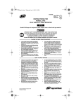
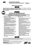
SERIES QS1L AND QS1T LEVER INLINE MOTOR AND GEARING
36
8
39
35
9
6
11
17
13
15
16
18
(Dwg. TPA1757-1)
6A
12
14
P 7440 Edition 10
23
21
17
18
19
20
10
11
12
13
14
15
16
4A
5
6
6A
7
8
9
1
2
3
4
Item
Motor Housing . . . . . . . . . . . . . . . . . . . . . . . . . . . . . .
Housing O-ring . . . . . . . . . . . . . . . . . . . . . . . . . . . . . .
Housing Screw . . . . . . . . . . . . . . . . . . . . . . . . . . . . . .
Reverse Valve Assembly
for Models with an Automatic
Shutoff Valve . . . . . . . . . . . . . . . . . . . . . . . . . . . .
for Models without an Automatic
Shutoff Valve . . . . . . . . . . . . . . . . . . . . . . . . . . . .
Reverse Valve Seal . . . . . . . . . . . . . . . . . . . . . . . . .
Throttle Plunger . . . . . . . . . . . . . . . . . . . . . . . . . . . . .
Back Cap . . . . . . . . . . . . . . . . . . . . . . . . . . . . . . . . . . . .
Warning Label (for direct drive models only) . . . . . .
Back Cap Gasket . . . . . . . . . . . . . . . . . . . . . . . . . . . . .
Muffler Element (3) . . . . . . . . . . . . . . . . . . . . . . . . . .
Memory Chip (for models with
memory chip only) . . . . . . . . . . . . . . . . . . . . . . . . . . . .
Throttle Lever . . . . . . . . . . . . . . . . . . . . . . . . . . . . . . .
Throttle Lever Pin . . . . . . . . . . . . . . . . . . . . . . . . . . . .
Throttle Valve Seat . . . . . . . . . . . . . . . . . . . . . . . . . .
Throttle Valve . . . . . . . . . . . . . . . . . . . . . . . . . . . . . . .
Throttle Valve Spring . . . . . . . . . . . . . . . . . . . . . . . . .
Exhaust Diffuser . . . . . . . . . . . . . . . . . . . . . . . . . . . . .
Inlet Bushing Assembly
for 1/4-18 NPT thread . . . . . . . . . . . . . . . . . . . . .
for 1/4-19 BSPT thread . . . . . . . . . . . . . . . . . . . .
Inlet Bushing Seal . . . . . . . . . . . . . . . . . . . . . . . . . .
Inlet Screen . . . . . . . . . . . . . . . . . . . . . . . . . . . . . . . .
Reverse Lever . . . . . . . . . . . . . . . . . . . . . . . . . . . . . . . .
Automatic Shutoff Valve (for all Models with
a Shutoff Clutch and Lever Permit Models
with a Cushion Clutch) . . . . . . . . . . . . . . . . . . . . . . . .
Rear End Plate Assembly (includes
rear rotor bearing) . . . . . . . . . . . . . . . . . . . . . . . . . . . .
Parts Description
TRH-A12-1
TRH-A435
TRH-A465
TRH-A465-B
AF120-290
TRH-61
TRH-273
TRH-800
TRL-274
TRL-98
TRH-303
TRD-A302
TRL-51
TRH-123
TRH-A3291
R1A-159
TRL-302
TRL-2311
TRL-99
TRL-A283
TRL-311
TRH-A329
TRL-40
TRH-104
TRH-330
Part Number
38
35
36
37
28
29
30
31
32
33
34
22
23
24
25
26
27
Item
Parts Description
TRH-A2169-10
TRH-A2169-12
TRH-A2169-16
TRH-17
TRH-425
TRH-28
TRH-81
TRD-53
TRH-42-5
TRH-A11
TRH-98-2
TRH-24
TRH-211
TRH-207
TRH-53
TRH-12-2
8SL-305
TRH-A3
TRH-98
TRH-98-1
Part Number
Continued to next page
Rear End Plate Face Plate . . . . . . . . . . . . . . . . . . . . .
Rear End Plate Assembly Retainer . . . . . . . . . . . . . .
Cylinder Assembly . . . . . . . . . . . . . . . . . . . . . . . . . . . .
Cylinder Rear Alignment Pin . . . . . . . . . . . . . . . . .
Cylinder Front Alignment Pin . . . . . . . . . . . . . . . .
Rotor
for Models with an Automatic
Shutoff Valve . . . . . . . . . . . . . . . . . . . . . . . . . . . .
for Models without an Automatic
Shutoff Valve . . . . . . . . . . . . . . . . . . . . . . . . . . . .
Vane Packet (set of 5 Vanes) . . . . . . . . . . . . . . . . . . .
Front End Plate Assembly . . . . . . . . . . . . . . . . . . . . .
End Plate Alignment Pin . . . . . . . . . . . . . . . . . . . .
Front Rotor Bearing . . . . . . . . . . . . . . . . . . . . . . . .
Motor Seal . . . . . . . . . . . . . . . . . . . . . . . . . . . . . . . . . .
Motor Clamp Washer . . . . . . . . . . . . . . . . . . . . . . . . .
Push Rod (for Models with an
Automatic Shutoff Valve) . . . . . . . . . . . . . . . . . . . . . .
Gear Retainer . . . . . . . . . . . . . . . . . . . . . . . . . . . . . . .
Gear Head Spacer . . . . . . . . . . . . . . . . . . . . . . . . . . .
Planet Gear Head Drive Plate (for Series
QS1L28 and QS1T28) . . . . . . . . . . . . . . . . . . . . . . . .
Planet Gear Head Assembly (includes gear shafts)
for Series QS1L02, QS1T02 QS1L05,
QS1T05, QS1L10,QS1T10, QS1L28
and QS1T28 . . . . . . . . . . . . . . . . . . . . . . . . . . . . .
for Series QS1L17, QS1T17,
QS1L20C and QS1T20C . . . . . . . . . . . . . . . . . .
for Series QS1L20S, QS1T20S and
QS1L20D . . . . . . . . . . . . . . . . . . . . . . . . . . . . . . .
When Ordering, use applicable Part Number
SERIES QS1L AND QS1T LEVER INLINE MOTOR AND GEARING
24
P7440 Edition 10
Planet Gear (3 for each Gear Head)
for Series QS1L02, QS1T02, QS1L05,
QS1T05, QS1L10 and QS1T10 . . . . . . . . . . . . . .
for Series QS1L17, QS1T17,
QS1L20C and QS1T20C . . . . . . . . . . . . . . . . . . .
for Series QS1L20S, QS1T20S and
QS1T20D . . . . . . . . . . . . . . . . . . . . . . . . . . . . . . . .
Gear Head Pinion
for Series QS1L17, QS1T17,
QS1L20C and QS1T20C . . . . . . . . . . . . . . . . . . .
for Series QS1L20S, QS1T20S and
QS1L20D . . . . . . . . . . . . . . . . . . . . . . . . . . . . . . . .
Planet Gear Head Spacer . . . . . . . . . . . . . . . . . . . . . .
39
* Not Illustrated.
41
40
Parts Description
Item
TRH-17-21
TRH-82
TRH-17-18
TRH-10-10
TRH-10-12
TRH-10-16
43
44
45
46
*
*
42
Part Number Item
Parts Description
Spindle Assembly (includes all spindle gearing)
for Series QS1L02, QS1T02, QS1L05,
QS1T05, QS1L28 and QS1T28 . . . . . . . . . . . . . .
for Series QS1L10, QS1T10, QS1L17,
QS1T17, QS1L20S, QS1T20S and
QS1L20D . . . . . . . . . . . . . . . . . . . . . . . . . . . . . . . .
for Series QS1L20C, QS1T20C . . . . . . . . . . . . .
Gear Case . . . . . . . . . . . . . . . . . . . . . . . . . . . . . . . . . . . .
Spindle Bearing . . . . . . . . . . . . . . . . . . . . . . . . . . . . . . .
Spindle Bearing Retaining Ring . . . . . . . . . . . . . . . . .
Spindle Bearing Seat . . . . . . . . . . . . . . . . . . . . . . . . . . .
Suspension Bail . . . . . . . . . . . . . . . . . . . . . . . . . . . . . . .
Piped-Away Exhaust Kit (optional) . . . . . . . . . . . . . . .
When Ordering, use applicable Part Number
SERIES QS1L AND QS1T LEVER INLINE MOTOR AND GEARING
TRH-A8-12
TRH-A8-10
TAH-37
TRH-510
120A4-588
TRH-208
7L-365
LG1-K284
TRH-A8-16
Part Number
P 7440 Edition 10
25
is
Th
ge
Pa
lly
na
io
nt
te
in
ft
le
k
an
Bl
26
P7440 Edition 10
80
64
78
63
79
77
62
61
76
60
74
58
75
57
71
59
72
56
73
55
54
70
69
53
67
51
68
52
50
47
65
46
(Dwg. TPA1758)
66
48
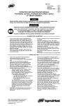
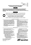
SERIES QS1L AND QS1T LEVER INLINE CLUTCHES
P 7440 Edition 10
27
60
61
62
63
64
46
47
48
49
50
51
52
53
54
55
56
57
58
59
Item
Automatic Shutoff Clutch Assembly
with heavy clutch spring (standard) . . . . . . . . . .
with medium clutch spring . . . . . . . . . . . . . . . . . .
with light clutch spring . . . . . . . . . . . . . . . . . . . . .
Clutch Return Spring . . . . . . . . . . . . . . . . . . . . . . . .
Clutch Input Driver . . . . . . . . . . . . . . . . . . . . . . . . .
Automatic Shutoff Plunger . . . . . . . . . . . . . . . . . . .
Automatic Shutoff Plunger Return Spring . . . . . .
Automatic Shutoff Pin . . . . . . . . . . . . . . . . . . . . . . .
Automatic Shutoff Pin Spring . . . . . . . . . . . . . . . . .
Clutch Shaft . . . . . . . . . . . . . . . . . . . . . . . . . . . . . . . .
Clutch Ball (1/8” diameter) (12) . . . . . . . . . . . . . . .
Cam Jaw . . . . . . . . . . . . . . . . . . . . . . . . . . . . . . . . . . .
Clutch Cam Ball Driver . . . . . . . . . . . . . . . . . . . . . .
Clutch Cam Ball (1/4” diameter) (3) . . . . . . . . . . . .
Clutch Driver Retaining Pin . . . . . . . . . . . . . . . . . . .
Cam Ball Seat . . . . . . . . . . . . . . . . . . . . . . . . . . . . . .
Clutch Spring
heavy (green) . . . . . . . . . . . . . . . . . . . . . . . . . . . .
medium (red) . . . . . . . . . . . . . . . . . . . . . . . . . . . .
light (orange) . . . . . . . . . . . . . . . . . . . . . . . . . . . .
Spring Seat . . . . . . . . . . . . . . . . . . . . . . . . . . . . . . . . .
Thrust Bearing . . . . . . . . . . . . . . . . . . . . . . . . . . . . .
Clutch Adjusting Nut Washer . . . . . . . . . . . . . . . . .
Clutch Adjusting Nut . . . . . . . . . . . . . . . . . . . . . . . .
Clutch Adjusting Nut Stop . . . . . . . . . . . . . . . . . . . .
Cushion Clutch Assembly
with heavy clutch spring (standard) . . . . . . . . . .
Parts Description
76
77
78
79
80
81
TRH-H583
TRH-M583
TRH-XL583
TRH-623
161A32-105
TRH-582
TRH-588
3S3-701
TRH-AH579-C
71
72
73
74
75
65
66
67
68
69
70
Item
TRH-AH579
TRH-AM579
TRH-AL579
TRH-405
TRH-103
TRH-408
TRH-420
TRH-704
TRH-407
TRH-502
AV1-255
TRH-721
TRH-581
4U-722
TRH-188
TRH-627
Part Number
Parts Description
with medium clutch spring . . . . . . . . . . . . . . . .
with light clutch spring . . . . . . . . . . . . . . . . . . . .
Clutch Return Spring . . . . . . . . . . . . . . . . . . . . . . .
Clutch Input Driver . . . . . . . . . . . . . . . . . . . . . . . .
Clutch Pushrod . . . . . . . . . . . . . . . . . . . . . . . . . . . .
Clutch Shaft . . . . . . . . . . . . . . . . . . . . . . . . . . . . . . .
Clutch Ball (1/8” diameter) (12) . . . . . . . . . . . . . .
Cam Jaw
for Series QS1T02, QS1L02, QS1T05,
QS1L05, QS1T10 and QS1L10 . . . . . . . . . . . . .
for Series QS1T17, QS1L17, QS1T20,
QS1L20, QS1T28 and QS1L28 . . . . . . . . . . . . .
Clutch Cam Ball Driver . . . . . . . . . . . . . . . . . . . . . .
Clutch Cam Ball (1/8” diameter) (11) . . . . . . . . . .
Clutch Cam Ball Driver Retaining Pin . . . . . . . . . .
Cam Ball Seat . . . . . . . . . . . . . . . . . . . . . . . . . . . . . .
Clutch Spring
heavy (green) . . . . . . . . . . . . . . . . . . . . . . . . . . . .
medium (red) . . . . . . . . . . . . . . . . . . . . . . . . . . .
light (orange) . . . . . . . . . . . . . . . . . . . . . . . . . . . .
Spring Seat . . . . . . . . . . . . . . . . . . . . . . . . . . . . . . . .
Thrust Bearing . . . . . . . . . . . . . . . . . . . . . . . . . . . . .
Clutch Adjusting Nut Washer . . . . . . . . . . . . . . . . .
Clutch Adjusting Nut . . . . . . . . . . . . . . . . . . . . . . . .
Clutch Adjusting Nut Stop . . . . . . . . . . . . . . . . . . .
Clutch Shaft (for Models with
Direct Drive only) . . . . . . . . . . . . . . . . . . . . . . . . . . . .
When Ordering, use applicable Part Number
SERIES QS1L AND QS1T LEVER INLINE CLUTCHES
TRH-786
TRH-H583
TRH-M583
TRH-XL583
TRH-623
161A32-105
TRH-582
TRH-588
3S3-701
TRH-722-C
TRH-581-C
AV1-255
TRH-188
TRH-627-C
TRH-721-C
TRH-AM579-C
TRH-AL579-C
TRH-405
TRH-103
TRH-236-C
TRH-502
AV1-255
Part Number
28
P7440 Edition 10
97
96
92A
92
93
95
92B
98
94
91
90
89
88
82
86
85
83
87
87A
84
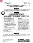
SERIES QS1L AND QS1T LEVER INLINE GRIP AND BIT DRIVERS
84
(Dwg. TPA1759-2)
85
P 7440 Edition 10
85
82
83
84
Item
Bit Holder Assembly
with 1/4” Quick Release Bit Holder (for
all Models with Lever Permit) . . . . . . . . . .
with 1/4” Quick Release Bit Holder (for
all Models with Lever Start) . . . . . . . . . . . .
with 1/4” Bit Finder Bit Holder (for all
Models with Lever Permit) . . . . . . . . . . . .
with 1/4” Bit Finder Bit Holder (for all
Models with Lever Start) . . . . . . . . . . . . . .
with 5 mm Double End Quick Release
Bit Holder (for all Models with
Lever Permit) . . . . . . . . . . . . . . . . . . . . . . . .
with 5 mm Double End Quick Release
Bit Holder (for all Models with
Lever Start) . . . . . . . . . . . . . . . . . . . . . . . . .
with 1/4” Double End Quick Release
Bit Holder (for all Models with
Lever Permit) . . . . . . . . . . . . . . . . . . . . . . . .
with 1/4” Double End Quick Release
Bit Holder (for all
Models with Lever Start) . . . . . . . . . . . . . .
Clutch Housing . . . . . . . . . . . . . . . . . . . . . . . . . . .
Clutch Housing Bearing . . . . . . . . . . . . . . . . . .
Bit Holder
for 1/4” Quick Release Bit Holder . . . . . .
for 1/4” Bit Finder Bit Holder . . . . . . . . . .
for 5 mm Double End Quick Release
Bit Holder . . . . . . . . . . . . . . . . . . . . . . . . . .
for 1/4” Double End Quick Release
Bit Holder . . . . . . . . . . . . . . . . . . . . . . . . . . .
Bit Retaining Ball
for metric Bit Holders . . . . . . . . . . . . . . . . .
for all other Bit Holders . . . . . . . . . . . . . . .
Parts Description
TRH-629-3M
R000B-263
TRH-586-Q4D
86
Item
Parts Description
Bit Retaining Spring ( for Bit Finder
Bit Holders) . . . . . . . . . . . . . . . . . . . . . . . . . . . . .
Shutoff Spacer (for all Models with
TRH-A580-PQ4
87
Lever Start only) . . . . . . . . . . . . . . . . . . . . . . . . .
Wave Washer (for all Models with
TRH-A580-NQ4
87A
Lever Start only) . . . . . . . . . . . . . . . . . . . . . . . . .
Bit Retaining Sleeve (for Quick Release
TRH-A580-PQ4F
88
Bit Holders) . . . . . . . . . . . . . . . . . . . . . . . . . . . . .
Retaining Sleeve Spring (for Quick
TRH-A580-NQ4F
89
Release Bit Holders) . . . . . . . . . . . . . . . . . . . . . .
Spring Seat (for Quick Release Bit Holders) . .
90
Retaining Ring (for Quick Release
TRH-A580-PQ5MD 91
Bit Holders) . . . . . . . . . . . . . . . . . . . . . . . . . . . . .
Non-Rotating Bit Finder (for Bit Finder
92
Bit Holders) . . . . . . . . . . . . . . . . . . . . . . . . . . . . .
TRH-A580-NQ5MD
Spring (for Bit Finder Bit Holders) . . . . . . . . . .
92A
Finder Retaining Spring (for Bit Finder
92B
Bit Holders) . . . . . . . . . . . . . . . . . . . . . . . . . . . . .
TRH-A580-PQ4D
Housing Grip . . . . . . . . . . . . . . . . . . . . . . . . . . . . .
93
Nameplate . . . . . . . . . . . . . . . . . . . . . . . . . . . . . .
94
Warning Label . . . . . . . . . . . . . . . . . . . . . . . . . . .
TRH-A580-NQ4D
95
Grip Retaining Ring . . . . . . . . . . . . . . . . . . . . . . . .
TRH-580
96
Clutch Adjusting Hole Cover
TRH-105
97
Cover with a flange (standard) . . . . . . . . . . .
Cover without a flange (optional) . . . . . . . .
TRH-586-H4
Clutch Housing Cap (for Quick
TRH-583-Q4
98
Release Holders) . . . . . . . . . . . . . . . . . . . . . . . . . .
Clutch Housing Spanner Wrench . . . . . . . . . . . . .
TRH-586-5MD
*
Part Number
When Ordering, use applicable Part Number
SERIES QS1L AND QS1T LEVER INLINE GRIP AND BIT DRIVERS
~
29
TRH-19
TRH-478
TRH-40-23
TRH-40-24
102A60-628
TRH-40-A145
TRH-301
TRH-99
TRH-197
TRH-873
102A60-242
TRH-853
TRH-931
TRH-244
TRH-930
TRH-592
TRH-591
TRH-241
Part Number
MAINTENANCE
CLUTCH SPRING SELECTION CHART
Tool
All Series QS
Inline
Screwdrivers
Free
Speed
(rpm)
TORQUE RANGE (Soft Draw)
Light Clutch
Spring (Orange)
Medium Clutch
Spring (Red)
Heavy Clutch
Spring (Green)
2800
1.7 to 9.7 in-lbs.
(0.19 to 1.1 Nm)
---------------------------------------
---------------------------------------
2000
1.7 to 9.7 in-lbs.
(0.19 to 1.1 Nm)
7.9 to 22.1 in-lbs.
(0.89 to 2.50 Nm)
---------------------------------------
1710
1.7 to 9.7 in-lbs.
(0.19 to 1.1 Nm)
7.9 to 27.3 in-lbs.
(0.89 to 3.08 Nm)
---------------------------------------
1000
1.7 to 9.7 in-lbs.
(0.19 to 1.1 Nm)
7.9 to 27.3 in-lbs.
(0.89 to 3.08 Nm)
13.3 to 40.0 in-lbs.
(1.50 to 4.52 Nm)
500
1.7 to 9.7 in-lbs.
(0.19 to 1.1 Nm)
7.9 to 28.3 in-lbs.
(0.89 to 3.20 Nm)
13.3 to 47.8 in-lbs.
(1.50 to 5.40 Nm)
250
1.7 to 9.7 in-lbs.
(0.19 to 1.1 Nm)
7.9 to 28.3 in-lbs.
(0.89 to 3.20 Nm)
13.3 to 47.8 in-lbs.
(1.50 to 5.40 Nm)
Therefore, the adjustment, although simple, should only be
attempted by a competent technician using the proper
equipment.
Always wear eye protection when operating or performing
maintenance on this tool.
Always turn off the air supply and disconnect the air
supply hose before installing, removing or adjusting any
accessory on this tool, or before performing any
maintenance on this tool.
LUBRICATION
Each time a Series QS Screwdriver is disassembled for
maintenance and repair or replacement of parts, lubricate
the tool as follows:
1.
2.
3.
Coat all exposed gears with Ingersoll-Rand No. 67
Grease and work some of the Grease into the gearing
of the Spindle Assembly (42).
Work approximately 6 to 8 cc of Ingersoll-Rand No.
28 Grease into the ball pockets, jaws, adjusting nut
lock and shaft threads of the clutch mechanism.
Use Ingersoll-Rand No. 10 Oil to lubricate the motor.
Inject approximately 1 to 2 cc of oil into the air inlet
before attaching the air hose to the tool.
SPEED ADJUSTMENT
The Back Cap (6) has a small, molded stud on the end face
of the Cap nearest the Exhaust Diffuser (15). That stud
controls the radial location of the Diffuser which controls
the opening size of the exhaust ports. Take an initial
reading of the tool speed by applying a tachometer with a
convex tip to the inside of the Bit Holder (84). Using the
procedure required to activate the motor of your particular
model tool, bring the motor to maximum free speed.
After determining the actual velocity, shut off the air
supply and disconnect the air line. Use a 3/4” wrench to
loosen the Inlet Bushing. The longest slot in the Exhaust
Diffuser will contain the molded stud on the Back Cap.
Rotate the Diffuser to open the exhaust ports to increase
speed or rotate it to restrict the exhaust to reduce speed.
Being careful not to allow the Diffuser to damage the
molded stud, tighten the Inlet Bushing to 15 ft-lbs. (20
Nm) torque. Connect the air line and restore the air supply
and check the velocity again. Determine which direction
you need to rotate the Diffuser to obtain the desired speed
and then rotate it accordingly. Best results are achieved by
using gradual increments and frequent tachometer
readings. Be sure to turn off the air supply and disconnect
the line when making adjustments.
In addition to adjustable clutches for controlling torque,
Series QS Lever Inline Screwdrivers are furnished with the
ability to precisely control speed, within certain ranges.
Setting the speed requires a tachometer.
30
P7440 Edition 10
MAINTENANCE (Continued)
DISASSEMBLY
General Instructions
1.
2.
3.
4.
Do not disassemble the tool any further than necessary to replace or repair damaged parts.
Whenever grasping a tool or part in a vise, always use
leather-covered or copper-covered vice jaws to protect
the surface of the part and help prevent distortion.
This is particularly true of threaded members and
housings.
Do not remove any part which is a press fit in or on a
subassembly unless the removal of that part is necessary for repairs or replacement.
Do not disassemble the tool unless you have a complete set of gaskets and o-rings for replacement.
Disassembly of the Tool
Each Series QS Lever Inline Screwdriver is made using
four modules or units which include a motor housing unit,
a motor unit, a clutch with bit holder unit and a combined
gearing with spindle unit. The tool can be disassembled for
repairs to each individual unit without disturbing the other
units. To separate the modules, proceed as follows:
The thread in the following step is a left hand thread.
Rotate the Bit Finder or Housing Cap clockwise to remove
it.
1. For models with Bit Finder Bit Holders, unscrew and
remove the Non-Rotating Bit Finder (92).
For models with Quick Release Bit Holders, unscrew
and remove the Clutch Housing Cap (98). Use a thin
blade screwdriver to spiral the Retaining Ring (91)
out of the groove in the end of the Bit Holder (84).
Being careful not to loose the Bit Retaining Ball (85),
slide the Spring Seat (90), Retaining Sleeve Spring
(89) and the Bit Retaining Sleeve (88) off the Bit
Holder.
5.
6.
7.
8.
9.
10.
11.
12.
13.
14.
15.
16.
17.
18.
19.
The thread in the following step is a left hand thread.
Rotate the Cover clockwise to remove it.
2.
3.
4.
Unscrew and remove the Clutch Adjusting Hole Cover
(97). There are two sets of threads with a non-threaded
section between them on the ClutchHousing (82).
Using external retaining ring pliers or a thin blade
screwdriver, remove the Grip Retaining Ring (96)
from the groove in the Clutch Housing.
Pull the Housing Grip (93) of the front end of the tool.
The thread in the following step is a left hand thread.
Rotate the Clutch Housing clockwise to remove it.
P 7440 Edition 10
20.
21.
22.
Clamp the Inlet Bushing (16) in leather-covered or
copper-covered vise jaws and using a 1-1/16” wrench
on the flats of the Gear Case (43) and the Clutch
Housing Spanner Wrench (Part No. TRH-478) in the
clutch housing slot, unscrew and remove the Clutch
Housing.
Push on the output end of the Bit Holder (85) to
remove it from the Clutch Housing (82).
For Models with Lever Start, slide the Shutoff Spacer
(87) and Wave Washer (87A) off the Bit Holder.
If the Clutch Housing Bearing (83)is worn and must
be replaced, press it from the Clutch Housing.
Carefully remove the Clutch Assembly or Clutch Shaft
(81), the Clutch Input Driver (47 or 66), the Clutch
Return Spring (46 or 65), and the Push Rod (67).
Lightly grasp the flats of the Gear Case in leather-covered or copper-covered vise jaws with the Inlet Bushing upward.
Place a 1-3/16” open end wrench on the flats of the
Back Cap (6) to prevent it from rotating, and use a 3/
4” wrench to unscrew and remove the Inlet Bushing.
Lift the Exhaust Diffuser (15) off the Back Cap.
If the Throttle Valve Spring (14) did not come out of
the tool with the Inlet Bushing, use needle nose pliers
to remove it and the Throttle Valve (13) from the
Motor Housing (1).
To remove the Throttle Valve Seat, insert a hooked
tool through the central opening of the Seat and pull it
from the Motor Housing.
Using a 1/16” pilot punch, tap the Throttle Lever Pin
(11) out of the Back Cap and remove the Throttle
Lever (10).
Pull the Throttle Plunger (5) out of the Motor Housing and remove the assembly from the vise.
Holding the assembly horizontally, remove the Back
Cap, the Memory Chip (9) (if included with the tool),
the Back Cap Gasket (7) and the Shutoff Valve (20) (if
included with the tool).
If the Muffler Elements (8) need to be cleaned or
replaced, pull them out of the Back Cap.
Grasp the flats at the inlet end of the Motor Housing
in leather-covered or coper-covered vise jaws, and
using a 1-1/16” wrench on the flats of the Motor Housing, unscrew and separate the Gear Case from the
Motor Housing.
Set the assembled Gear Case on the workbench.
Remove the Motor Clamp Washer (33) and the Motor
Seal (32) from the assembled motor in the Housing.
Tap the Motor Housing on a wood block to remove
the Motor Assembly from the Housing.
Disassembly of the Adjustable Shutoff Clutch
1.
Using a thin blade screwdriver, pry the Clutch Adjusting Nut Stop (64) off the end of the Clutch Shaft (52).
31
MAINTENANCE (Continued)
2.
Insert the tip of a #1 Phillips Head Screwdriver into
the adjustment opening between the Clutch Adjusting
Nut (63) and the Clutch Adjusting Nut Washer (62).
Rotate the screwdriver clockwise to thread the Adjustment Nut off the Clutch Shaft.
2.
Insert the tip of a #1 Phillips Head Screwdriver into
the adjustment opening between the Clutch Adjusting
Nut (79) and the Clutch Adjusting Nut Washer (78).
Rotate the screwdriver clockwise to thread the Adjustment Nut off the Clutch Shaft.
In the following step, the Clutch Cam Balls will be free to
fall from the assembly when the Cam Ball Seat is moved.
Make certain the Balls fall into a non-damaging container.
In the following step, the Clutch Cam Balls will be free to
fall from the assembly when the Cam Ball Seat is moved.
Make certain the Balls fall into a non-damaging container.
3.
3.
4.
Holding the assembly over a small pasteboard box,
slide the Adjusting Nut Washer, the Thrust Bearing
(61), the Spring Seat (60), the Clutch Spring (59) and
the Cam Ball Seat (58) off the Clutch Shaft. Allow the
three Clutch Cam Balls (56) to fall into the pasteboard box.
The Clutch Cam Ball Driver (55) has a cross hole that
is larger on one side than the other. Insert a 1/16” drill
shank or piece of wire into the smaller hole and gently
push the Clutch Driver Retaining Pin (57) out of the
larger hole and out of the Driver and the Clutch Shaft.
4.
Holding the assembly over a small pasteboard box,
slide the Adjusting Nut Washer, the Thrust Bearing
(77), the Spring Seat (76), the Clutch Spring (75) and
the Cam Ball Seat (74) off the Clutch Shaft. Allow the
eleven Clutch Cam Balls (72) to fall into the pasteboard box.
The Clutch Cam Ball Driver (71) has a cross hole that
is larger on one side than the other. Insert a 1/16” drill
shank or piece of wire into the smaller hole and gently
push the Clutch Driver Retaining Pin (73) out of the
larger hole and out of the Driver and the Clutch Shaft.
In the following step, the Clutch Balls will be free to fall
from the assembly when the Cam Jaw is moved along the
Clutch Shaft. Make certain the Balls fall into a nondamaging container.
In the following step, the Clutch Balls will be free to fall
from the assembly when the Cam Jaw is moved along the
Clutch Shaft. Make certain the Balls fall into a nondamaging container.
5.
5.
6.
7.
8.
Holding the assembly over a small pasteboard box,
and using care to drop the twelve Clutch Balls (53)
into the box, slide the Clutch Cam Ball Driver and
Cam Jaw (54) off the Clutch Shaft. If grease held
some of the Balls inside the jaw cavity, remove them.
With the large end of the Clutch Shaft downward,
depress the Automatic Shutoff Pin (50) with varying
amounts of finger pressure while tapping the large
end edge of the Clutch Shaft on a piece of wood until
the Automatic Shutoff Plunger (48) protrudes slightly
from the end of the Shaft. Grasp the Plunger and
carefully pull it out of the Clutch Shaft.
Remove the Automatic Shutoff Pin and Automatic
Shutoff Pin Spring (51) from the Clutch Shaft. The
Pin Spring should remain in the pin recess when the
Pin is removed. To separate the Spring from the Pin,
gently rotate the Spring while pulling it from the
recess to avoid elongating the Spring.
Using a hooked tool, reach into the opening in the
end of the Clutch Shaft and carefully pull the Automatic Shutoff Plunger Return Spring (49) out of the
Shaft without elongating the Spring.
Disassembly of the Adjustable Cushion Clutch
1. Using a thin blade screwdriver, pry the Clutch Adjusting Nut Stop (80) off the end of the Clutch Shaft (68).
32
Holding the assembly over a small pasteboard box,
and using care to drop the twelve Clutch Balls (69)
into the box, slide the Clutch Cam Ball Driver and
Cam Jaw (70) off the Clutch Shaft. If grease held
some of the Balls inside the jaw cavity, remove them.
Disassembly of the Gearing
1.
2.
Using snap ring pliers, remove the Gear Retainer (35)
from the motor end of the Gear Case (43) and remove
the Gear Head Spacer (36) as well.
For Series QS1L02, QS1T02, QS1L05, QS1T05,
QS1L10 and QS1T10, lightly rap the motor end of the
Gear Case on a wooden work bench top to remove the
three Planet Gears (39), the Planet Gear Head
Assembly (38) and the Planet Gear Head Spacer (41).
For Series QS1L17, QS1T17, QS1L20 and QS1T20,
lightly rap the motor end of the Gear Case on a
wooden work bench top to remove the three Planet
Gears (39), The Gear Head Pinion (40), the Planet
Gear Head Assembly (38) and the Planet Gear Head
Spacer (41).
For Series QS1L28 and QS1T28, lightly rap the motor
end of the Gear Case on a wooden work bench top to
remove the Planet Gear Head Drive Plate (37), the
P7440 Edition 10
MAINTENANCE (Continued)
3.
4.
Planet Gear Head Assembly (38) and the Planet Gear
Head Spacer (41).
Using snap ring pliers, remove the Spindle Bearing
Retaining Ring (45).
Stand the Gear Case on the table of an arbor press
with the output spindle upward. Using a rod that
neatly fits inside the internal hex of the Spindle (42),
press the Spindle Assembly out of the Spindle Bearing
(44).
Do not remove the Bearing in the following step unless you
have a new replacement available for installation. The
Bearing will be damaged by the removal process.
5.
6.
Invert the Gear Case on the table of an arbor press so
that the end face having four notches makes contact
with the table. Using a rod against the inner race of
the Spindle Bearing, press the Bearing from the Gear
Case.
If the Spindle Bearing Seat (46) must be replaced, use
a small, thin blade screwdriver to spiral it out of the
groove in the Gear Case.
Disassembly of the Motor
1.
2.
3.
4.
5.
Using snap ring pliers, remove the Rear End Plate
Assembly Retainer (23) from the shaft of the Rotor
(27).
Pull the Rear End Plate Face Plate (22) and Rear End
Plate Assembly (21) off the hub of the Rotor.
Lift the Cylinder (24) from the Rotor.
Remove the Vanes (28) from the Rotor.
Support the Front End Plate Assembly (29), as near
the rotor body as possible, on the table of an arbor
press and press the Rotor from the Front Rotor Bearing (31). Remove the Bearing from the Front End
Plate.
Disassembly of the Housing
1.
2.
3.
4.
Pull the Reverse Lever (19) off the inlet end of the
Motor Housing (1).
Using a #2 Phillips Head Screwdriver, unscrew and
remove the Housing Screw (3).
Insert a 5/16” wooden dowel between 6 and 8 inches
long, into the inlet end of the Motor Housing and
push the Reverse Valve Assembly (4) out the motor
end of the Housing.
Use a hooked tool to pull the Housing O-ring (2) out
of the Motor Housing.
2.
3.
4.
5.
6.
Assembly of the Housing
1.
2.
3.
4.
5.
6.
7.
P 7440 Edition 10
Lubricate the Housing O-ring (2) with o-ring lubricant
and install it at the bottom of the cylinder bore in the
Motor Housing (1).
Inspect the face and o-ring on the hub of the Reverse
Valve Assembly (4) for nicks or damage. Replace the
Reverse Valve Assembly if any damage is evident.
Lubricate the o-ring on the hub of the Reverse Valve
Assembly with o-ring lubricant and insert the Assembly, o-ring end leading, into the cylinder bore of the
Motor Housing. Push the Assembly toward the bottom of the cylinder bore until it “snaps” into its proper
location.
Rotate the Valve inside the Housing until the
threaded hole into the side of the Valve for the Motor
Housing Screw (3) aligns with the hole in the Motor
Housing.
Using a #2 Phillips Head Screwdriver, thread the
Motor Housing Screw into the Reverse Valve Assembly through the Housing until the underside of the
screw head stops against the Housing. Back the Screw
out of the Valve between 1/4 and 1/2 turn.
Align the open end of the slot inside the Reverse
Lever (19) with the head of the Housing Screw. From
the inlet end of the Housing, slide the Lever onto the
Housing, making certain the screw head enters the
slot, and move it along the Housing until it stops
against the housing shoulder.
Rotate the Lever to make certain the Valve only has
slight resistance.
Assembly of the Motor
1.
ASSEMBLY
General Instructions
1. Always press on the inner ring of a ball-type bearing
when installing the bearing on a shaft.
Always press on the outer ring of a ball-type bearing
when pressing the bearing into a bearing recess.
Whenever grasping a tool or part in a vise, always use
leather-covered or copper-covered vise jaws to protect
the surface of the part and help prevent distortion.
This is particularly true of threaded members and
housings.
Except for bearings, always clean every part and wipe
every part with a thin film of oil before installation.
Apply o-ring lubricant to all o-rings before final
assembly.
Check every bearing for roughness. If an open bearing
must be cleaned, wash it thoroughly in a clean, suitable
cleaning solution and dry with a clean cloth. Sealed or
shielded bearings should never be cleaned. Work
grease into every open bearing before installation.
2.
Place the Front End Plate (29) on the splined shaft of
the Rotor (27) with the bearing recess away from the
rotor body.
Place the Front Rotor Bearing (31) onto the shaft and
using a sleeve or piece of tubing that contacts the
inner race of the Bearing, press the Bearing onto the
33
MAINTENANCE (Continued)
shaft until the Front End Plate nearly contacts the
rotor body.
8.
9.
In the following step, the measurement must be made at
the end corner of the large rotor body.
3.
The clearance between the Front End Plate and Rotor
is critical. While pressing down with your finger on the
outer edge of the Front End Plate on the bearing side,
insert a 0.004” (0.1 mm) feeler gauge between the face
of the rotor body and the face of the End Plate at a
point that is 180 degrees from where the pressure is
applied. Refer to Dwg. TPA1740. To increase the gap,
support the End Plate and lightly tap the rotor shaft
with a plastic hammer; to decrease the gap, press the
Bearing farther onto the rotor shaft.
Assembly of the Gearing
1.
2.
3.
4.
Measurement of Front End Plate Clearance
PRESSURE
5.
6.
FEELER
GAUGE
7.
8.
(Dwg. TPA1740)
4.
5.
6.
7.
34
Wipe each Vane (28) with a light film of IngersollRand No.10 Oil and place a Vane in each slot in the
Rotor.
One end of the Cylinder Assembly (24) has a notch
that breaks the outer wall and end face of the Cylinder. With that end trailing, install the Cylinder Assembly over the Rotor and Vanes against the Front End
Plate. Make certain the Cylinder Front Alignment Pin
(26) enters the hole in the Front End Plate.
Install the Rear End Plate Assembly (21), flat face
leading, on the rear hub of the Rotor. Make certain
the Cylinder Rear Alignment Pin (25) enters the hole
in the Rear End Plate.
Examine the Rear End Plate Face Plate (22) for
scratches. If it is scratched, replace it. If it is not, slide
it onto the rear hub of the Rotor and onto the Cylinder Rear Alignment Pin against the Rear End Plate.
Some pressure may be required to fit the hole in the
Plate onto the Alignment Pin.
Using snap ring pliers, install the Rear End Plate
Assembly Retainer (23) in the annular groove on the
rear rotor hub to secure the assembly in position.
Set the assembled motor aside.
9.
Using a small screwdriver, work the Spindle Bearing
Seat (46) into the internal groove nearest the notched
end of the Gear Case (43).
Stand the Gear Case, notched end upward, on the
table of an arbor press. Using a piece of tubing that
contacts the outer race of the Spindle Bearing (44),
press a new Bearing into the Gear Case against the
Seat.
Lubricate the gears in the Spindle Assembly (42) with
Ingersoll-Rand No. 67 Grease.
Invert the Gear Case and using another piece of tubing that supports the inner race of the Bearing and
clears the output end of the Spindle Assembly, press
the Spindle Assembly into the Bearing from the motor
end of the Gear Case.
Using snap ring pliers, install the Spindle Bearing
Retaining Ring (45) in the external groove near the
driver end of the spindle.
Lightly lubricate the Planet Gear Head Spacer (41)
with Ingersoll-Rand No. 67 Grease and install it in the
Gear Case against the Spindle Assembly.
Lubricate the shafts of the Planet Gear Head Assembly (38) with Ingersoll-Rand No. 67 Grease and install
the Gear Head in the Gear Case meshing the spline
on the shaft with the gear teeth in the Spindle Assembly.
For Series QS1L02, QS1T02, QS1L05, QS1T05,
QS1L10 and QS1T10, lubricate the Planet Gears (39)
with Ingersoll-Rand No. 67 Grease and install them
on the shafts of the Planet Gear Frame Assembly.
For Series QS1L17, QS1T17, QS1L20 and QS1T20,
lubricate the Planet Gears (39) and Gear Head Pinion
(40) with Ingersoll-Rand No. 67 Grease and install the
Planet Gears on the shafts of the Planet Gear Frame
Assembly. Insert the Gear Head Pinion in the center
of the Planet Gears making certain the teeth mesh.
For Series QS1L28 and QS1T28, lubricate the Planet
Gear Head Drive Plate (37) with Ingersoll-Rand No.
67 Grease and install it on the shafts of the Planet
Gear Frame Assembly.
Install the Gear Head Spacer (36) against the Gears
or Drive Plate and secure the assembly by using snap
ring pliers to install the Gear Retainer (35) in the
internal groove at the motor end of the Gear Case.
Assembly of the Adjustable Cushion Clutch
1. Insert the small end of the Clutch Shaft (68) into the
end of the Cam Jaw (70) having the large opening and
slide the Shaft about half way into the Jaw.
P7440 Edition 10
MAINTENANCE (Continued)
2.
Drop the twelve Clutch Balls (69) into the Cam Jaw
forming a ring around the Clutch Shaft.
3. Lay a bead of Ingersoll-Rand No. 28 Grease, approximately 2 to 3 cc, on top of the Clutch Balls and then
bring the Clutch Shaft and Cam Jaw together capturing the Balls between them.
4. While holding the Shaft and Jaw together, slide the
Clutch Cam Ball Driver (71), large end leading, onto
the Clutch Shaft until it is against the Cam Jaw.
5. Rotate the Driver to align the large hole through one
wall of the Driver with the comparable size opening of
the cross hole through the Clutch Shaft. Push the
Clutch Cam Ball Driver Retaining Pin (73) into the
hole to lock the Driver in position on the Clutch Shaft.
6. Apply a coating of Ingersoll-Rand No. 28 Grease to
each of the eleven Clutch Cam Balls (72).
7. Holding the assembled Clutch Shaft with the Clutch
Cam Ball Driver upward, insert a lubricated Ball into
each of the eleven ball pockets in the Driver.
8. Slide the Cam Ball Seat (74), large end leading, onto
the Shaft against the Balls. Follow with the Clutch
Spring (75), Spring Seat (76), Thrust Bearing (77) and
the Clutch Adjusting Nut Washer (78) with the
smooth face leading.
9. Thread the Clutch Adjusting Nut (79), smooth face
trailing, onto the Clutch Shaft.
10. Insert the tip of a #1 Phillips Head Screwdriver into
the adjustment opening between the Clutch Adjusting
Nut and the Clutch Adjusting Nut Washer. Rotate the
screwdriver counterclockwise and thread the Adjustment Nut onto the Clutch Shaft until the external
groove for the Clutch Adjusting Nut Stop (80) is visible.
11. Install the Nut Stop in the groove.
Assembly of the Adjustable Shutoff Clutch
1.
2.
3.
4.
5.
6.
Hold the Clutch Shaft (52) in your hand with the large
end upward.
Insert the Automatic Shutoff Plunger Return Spring
(49) into the central opening in the large end of the
Clutch Shaft. Use a 1/8” dowel to push the Spring
below the cross hole for the Automatic Shutoff Pin
(50).
Insert the Automatic Shutoff Pin Spring (51) in the
end hole of the Automatic Shutoff Pin opposite the
pointed end. Rotate the Spring a little to keep it in the
hole.
Drip one or two drops of Ingersoll-Rand No. 10 Oil
into the central hole with the Plunger Return Spring.
Position the Shutoff Pin, Spring leading, in the cross
hole on the large end of the Clutch Shaft with the hole
in the Shutoff Pin aligned with the central hole containing the Return Spring.
Push on the pointed end of the Shutoff Pin to depress
the Spring while inserting the Automatic Shutoff
P 7440 Edition 10
7.
8.
9.
10.
11.
12.
13.
14.
15.
16.
17.
Plunger (48) into the central opening with the Return
Spring. The smaller center portion of the Shutoff
Plunger will allow the Shutoff Pin to spring outward
and capture the components within the Clutch Shaft
when properly positioned.
Insert the small end of the Clutch Shaft into the end
of the Cam Jaw (54) having the large opening and
slide the Shaft about half way into the Jaw.
Drop the twelve Clutch Balls (53) into the Cam Jaw
forming a ring around the Clutch Shaft.
Lay a bead of Ingersoll-Rand No. 28 Grease, approximately 2 to 3 cc, on top of the Clutch Balls and then
bring the Clutch Shaft and Cam Jaw together capturing the Balls between them.
While holding the Shaft and Jaw together, slide the
Clutch Cam Ball Driver (55), large end leading, onto
the Clutch Shaft until it is against the Cam Jaw.
Rotate the Driver to align the large hole through one
wall of the Driver with the comparable size opening of
the cross hole through the Clutch Shaft. Push the
Clutch Cam Ball Driver Retaining Pin (57) into the
hole to lock the Driver in position on the Clutch Shaft.
Apply a coating of Ingersoll-Rand No. 28 Grease to
each of the three Clutch Cam Balls (56).
Holding the assembled Clutch Shaft with the Clutch
Cam Ball Driver upward, insert a lubricated Ball into
each of the three ball slots in the Driver.
Slide the Cam Ball Seat (58), large end leading, onto
the Shaft against the Balls. Follow with the Clutch
Spring (59), Spring Seat (60), Thrust Bearing (61) and
the Clutch Adjusting Nut Washer (62) with the
smooth face leading.
Thread the Clutch Adjusting Nut (63), smooth face
trailing, onto the Clutch Shaft.
Insert the tip of a #1 Phillips Head Screwdriver into
the adjustment opening between the Clutch Adjusting
Nut and the Clutch Adjusting Nut Washer. Rotate the
screwdriver counterclockwise and thread the Adjustment Nut onto the Clutch Shaft until the external
groove for the Clutch Adjusting Nut Stop (64) is visible.
Install the Nut Stop in the groove.
Assembly of the Tool
1. Lightly grasp the flats at the inlet end of the Motor
Housing (1) in leather-covered or copper-covered vise
jaws with the motor bore upward.
2. Grasp the spline of the Rotor (27) in the assembled
motor and after aligning the End Plate Alignment Pin
(30) with the internal notch in the motor end of the
housing bore, insert the assembled motor into the
Motor Housing. Make certain the motor is far enough
into the Housing to have the undercut below the internal housing thread visible.
35
MAINTENANCE (Continued)
3.
Lubricate the Motor Seal (32) with o-ring lubricant
and install it around the Front End Plate (29) and into
the undercut in the Housing.
4. Align the tab of the Motor Clamp Washer (33) with
the internal notch in the Housing and install it over
the rotor hub and End Plate Alignment Pin against
the Motor Seal. Make certain the Pin enters the hole
in the Washer and the Washer is flat against the Seal.
5. Apply some Ingersoll-Rand No. 67 Grease to the
spline on the rotor shaft.
6. Thread the assembled Gear Case (43), output spindle
trailing, into the Motor Housing and using a 1-1/16”
wrench, tighten the joint between 15 and 20 ft-lbs. (20
and 27 Nm) torque.
7. For Models with a Clutch, place the narrow end of the
Clutch Return Spring (46 or 65) in the Gear Case
against the inner race of the Spindle Bearing (44).
8. For Models with Direct Drive, insert the hex end of
the Clutch Shaft (81) that does not have the step, into
the hex recess of the Spindle Assembly (42).
For Models with a Clutch, place the hex drive end of
the Clutch Input Driver (47 or 66) on the Spring and
compress the Spring until the hex on the Driver enters
the hex recess in the Spindle Assembly (42). While
holding the Driver in position, engage the raised bar
on the face of the Driver with the jaw of the Cam Jaw
(54 or 70).
9. If the Clutch Housing Bearing (83) was removed,
stand the Clutch Housing (82) on the table of an arbor
press with the smaller, externally threaded end downward.
10. Using a Needle Bearing Inserting Tool as shown in
Dwg. TPD786 with a 0.030” (0.76 mm) thick washer
that clears the inner bore and outer edge of the Bearing inserted between the Bearing and stop surface on
the tool, press the Bearing into the Clutch Housing.
The trailing end of the Bearing must be between
0.025” and 0.035” (0.63 and 0.89 mm) below the face
of the bore into which the Bearing is pressed.
Needle Bearing Inserting Tool
SHOULDER TO
REGULATE DEPTH
PILOT TO FIT I.D. OF BEARING.
LENGTH OF PILOT TO BE
APPROXIMATELY 1/8” LESS THAN
LENGTH OF BEARING
(Dwg. TPD786)
36
11. For Models with Lever Start, slide the Wave Washer
(87A) followed by the Shutoff Spacer (87) onto the
hub of the Bit Holder (84) and insert the Bit Holder
into the large end of the Clutch Housing (82) and
push the output end through the Clutch Housing
Bearing.
For Models with Lever Permit, insert the Bit Holder
(84) into the large end of the Clutch Housing (82) and
push the output end through the Clutch Housing
Bearing
The following step has parts with a left-hand thread.
Rotate the components counterclockwise to tighten them.
12. Install the assembled Clutch Housing over the clutch
components and thread it onto the Gear Case. Using
a 1-1/16” wrench on the flats of the Gear Case and the
Clutch Housing Spanner Washer (Part No. TRH-478)
in the clutch housing slot, tighten the joint between 15
and 20 ft-lbs. (20 and 27 Nm) torque.
13. Invert the assembled tool in the vise jaws and lightly
grasp the flats on the Gear Case with the inlet end of
the tool upward.
14. Insert a 5/8” dowel through the opening in the Back
Cap (6), and using the dowel as an alignment device,
install the three Muffler Elements (8) in the cavity of
the Back Cap. Make certain the notches in the outeredge of the Elements fit over the memory chip pocket
in the bottom of the Cap.
15. If the tool is equipped with a Memory Chip (9), install
it (with the leads entering first) in the pocket at the
bottom of the Back Cap.
16. Make certain the tab on the inside edge of the Back
Cap Gasket (7) is aligned with the pocket for the
Memory Chip and install the Gasket, metal face leading, in the recess of the Back Cap against the face with
the cavity containing the Muffler Elements.
17. Position the gasket end of the alignment dowel against
the inlet hub on the Motor Housing. Align the flats on
the Cap with the flats on the Housing. Orient the Back
Cap to clear the Reverse Lever (19) and slide the
Back Cap Assembly off the alignment dowel and onto
the Motor Housing.
18. For all Models with a Shutoff Clutch and Lever Permit Models with a Cushion Clutch, install the Push
Rod (34) into the central hole in the inlet hub. The
Rod will enter the assembled motor and disappear
from view when released. Install the Shutoff Valve
(20), small end first, in the same opening.
19. Being careful not to damage it, insert the Throttle
Valve Seat (12) into the central opening at the inlet
end of the Motor Housing at an angle until it clears
the threads in the Housing. Using a rod with a flat end
and no sharp edges, push the Seat to the bottom of the
opening until it seats flush.
P7440 Edition 10
MAINTENANCE (Continued)
20. Using needle nose pliers, insert the Throttle Valve
(13), long stem leading, into the opening against the
Seat. Center the Valve in the Seat.
21. Install the Throttle Valve Spring (14) in the opening
so that it encircles the Valve.
22. The Exhaust Diffuser (15) has one slot that is longer
than the other five slots. The Back Cap has a short,
molded stud projecting from the inlet end. Place the
Exhaust Diffuser against the Back Cap with the long
slot encircling the molded stud. Rotate the Diffuser
counterclockwise until the wall of the slot stops
against the stud. The exhaust ports are now in the full
open position which will provide maximum free speed.
23. If the Inlet Screen (18) required replacement, use a
wooden dowel to carefully push a new one into the
Inlet Bushing (16).
24. If the Inlet Bushing Seal (17) is nicked or damaged,
carefully install a new one over the threads of the Inlet
Bushing.
25. Thread the Inlet Bushing Assembly through the Diffuser and Back Cap into the Motor Housing. Using a
1-3/16” wrench on the flats of the Back Cap to keep it
from turning, tighten the Inlet Bushing between 15
and 20 ft-lbs. (20 and 27 Nm) torque.
26. The Throttle Plunger ( 5) has a lengthwise flat on the
outer edge at one end of the Plunger. Insert the
Plunger, flat end first, into the cross hole in the Housing. Push on the end of the Plunger to make certain it
springs back from contact with the stem of the Throttle Valve.
27. Position the Throttle Lever (10) in the slot in the Back
Cap and Motor Housing and using a 1/16” diameter
rod, align the holes through the Back Cap, Motor
Housing and Throttle Lever. While maintaining alignment, install the Throttle Lever Pin (11) in place of
the rod by tapping it through all three pieces.
28. Remove the tool from the vise jaws and install the
Housing Grip (93) over the Clutch Housing.
29. Install the Grip Retaining Ring (96) in the external
groove on the Clutch Housing ahead of the Grip to
retain the Grip on the Housing.
30. For Models with Quick Release Bit Holders, place the
Bit Retaining Ball (85) in the hole through the wall of
the Bit Holder and slide the Bit Retaining Sleeve (88),
large end trailing, onto the Bit Holder. Slide the
Retaining Sleeve Spring (89) and Spring Seat (90)
onto the Bit Holder and secure the components by
installing the Retaining Ring (91) in the external
groove at the output end of the Bit Holder.
31. Thread the Clutch Adjusting Hole Cover (97) onto
the Clutch Housing against the Housing Grip and
hand tighten it between 2 and 6 ft-lbs. (3 and 8 Nm)
torque.
The following step has parts with a left-hand thread.
Rotate the components counterclockwise to tighten them.
32. Thread the Non-Rotating Bit Finder (92) or Clutch
Housing Cap (98) onto the Clutch Housing and hand
tighten it between 2 and 6 ft-lbs. (3 and 8 Nm) torque.
TESTING THE TOOL
Before placing the tool back in service, test the tool in a
run down application to determine if adjustments are
necessary to satisfactorily perform the operation. Since five
interrelated adjustments can affect tool performance, only
experience, along with trial and error, can dictate which
adjustment or combination of adjustments will provide the
desired results.
The Clutch Spring (59 or 75), the clutch adjustment
procedure, the exhaust flow, the length of the Push Rod
(34) and the length of the Shutoff Valve (20) can
individually or collectively have an effect on torque and/or
speed. Always try to make adjustments before replacing or
attempting to modify components. If adjustments are
unable to provide the desired torque, it may be necessary
to install a lighter or heavier Clutch Spring.
If the tool ratchets when operated but fails to shutoff, it
may be necessary to shorten the Push Rod. Only shorten
the Push Rod in small increments. Increments between
0.005” and 0.010” (0.13 and 0.25 mm) are recommended. If
the tool stalls and does not shutoff, runs slower than
normal or has low power, the Shutoff Valve may require
lengthening. To lengthen the Shutoff Valve, grasp the stem
between two pieces of rubber or other non-slip, nonmarring material and rotate the molded nut
counterclockwise. Rotating the nut one half revolution will
lengthen the Valve approximately 0.009” (0.23 mm).
Should the stem of the Valve become bent, marred, nicked
or damaged in any way during the adjustment process,
replace it.
The thread in the following step is a left-hand thread.
Rotate the component counterclockwise to tighten it.
P 7440 Edition 10
37
MAINTENANCE (Continued)
TROUBLESHOOTING GUIDE
Trouble
Loss of Power
Motor won’t run
Gear Case gets hot
Probable Cause
Solution
Low air pressure
Check air supply. For top performance, the air pressure must be 90 psig (6.2 bar/620 kPa) at the inlet.
Plugged Inlet Bushing Screen
Clean the Inlet Bushing Screen using a clean, suitable
cleaning solution. If the Screen cannot be cleaned,
replace it.
Worn or broken Vanes
Replace a complete set of Vanes.
Worn or broken Cylinder
Replace the Cylinder if it is cracked or if the bore
appears wavy or scored.
Exhaust control restricted
Make certain the Exhaust Diffuser against the Back
Cap is in the fully open position.
Shutoff Valve too short
Lengthen the Shutoff Valve. Refer to “TESTING
THE TOOL” on page 37
Motor Clamp Washer binding
Remove the Gear Case make certain the Washer is
flat and the Motor Seal is properly positioned.
Gears binding
Clean and inspect all gearing. Replace any worn or
damaged gearing.
Push Rod worn
Install a new Push Rod.
Excessive grease
Clean and inspect Gear Case and gearing parts and
lubricate as instructed.
Worn or damaged parts
Clean and inspect the gear Case and Gearing.
Replace worn or broken components.
Inconsistent disengagement of Improper lubrication
the Adjustable Clutch
Remove the Adjustable Clutch mechanism and examine the parts. Lubricate as instructed.
Wrong Clutch Spring (using Heavy Change to Medium or Light Clutch Spring.
Clutch Spring on light torque
application)
Motor stalls before Adjustable Improper Clutch adjustment or
Check Clutch Adjustment and review tool perforClutch ratchets
improper tool ratio for application mance vs. requirements.
Low pressure at the inlet
Tool ratchets before shutoff
Check the air supply. For top performance, the air
pressure must be 90 psig (6.2bar/620kPa) at the inlet.
Insufficient grease
Lubricate the Clutch as instructed.
Improper exhaust control adjustment
Adjust the exhaust flow to obtain the desired speed.
Push Rod too long
Shorten the push Rod. Refer to“TESTING THE
TOOL” on page 37
Tool stalls without shutting off Shutoff Valve too short
Lengthen the Shutoff Valve. Refer to “TESTING
THE TOOL” on page 37
Too runs slower than normal
Lengthen the Shutoff Valve. Refer to “TESTING
THE TOOL” on page 37
Shutoff Valve too short
SAVE THESE INSTRUCTIONS. DO NOT DESTROY.
38
P7440 Edition 10
P 7440 Edition 10
39
is
Th
ge
Pa
lly
na
io
nt
te
in
ft
le
k
an
Bl
SERVICE CENTERS
For Order Entry and Order
Status
Ingersoll-Rand-Company
Distribution Center
P.O. Box 618
510 Hester Drive
White House, TN 37188
Phone: (615) 672-0321
Fax: (615) 672-0801
Technical Support
Ingersoll-Rand
1872 Enterprise Drive
Rochester, MI 48309
Phone: (248) 293-5700
Fax: (248) 293-5800
IR Equipment Sales Stores
Tennessee (Continued)
Arizona
820 N. 17th Avenue
Phoenix, AZ 85007
Phone: (602) 258-6493
Fax: (602) 253-9041
1500 J. P. Hennessey Drive
LaVergne, TN 37086-3521
Phone: (615) 641-3000
Fax: (615) 641-3040
California
12747 Schabarum Ave.
Los Angeles, CA 91706-6802
Phone: (626) 337-4545
Fax: (626) 337-1707
1851 Bell Ave
PO Box 38406
Sacramento, CA 95838
Phone: (916) 641-1994
Fax: (916) 641-1872
1944 Marina Blvd.
San Leandro, CA 94577
Phone: (510) 357-9131
Fax: (510) 483-7287
National Sales Office
Business Development Center
1467 Route 31 South
Annandale, NJ 08801
Phone: (908) 238-7000
Maryland
5681 Main Street
PO Box 7464
Elkridge, MD 21075
Phone: (410) 796-3200
Fax: (410) 796-3350
Regional Sales Offices
Massachusetts
300 Turnpike Road, Rte. 9
Southboro, MA 01772
Phone: (508) 481-1350
Fax: (508) 481-2014
Chicago, IL
888 Industrial Drive
Elmhurst, IL 60126
Phone: (630) 530-3800
Fax: (630) 530-3891
Detroit, MI
1872 Enterprise Drive
Rochester, MI 48309
Phone: (248) 293-5700
Fax: (248) 293-5800
Houston, TX
450 Gears Road
Suite 210
Houston, TX 77067-4516
Phone: (281) 872-6800
Fax: (281) 872-6807
Los Angeles, CA
13107 Lakeland Road
Santa Fe Springs, CA
90670-0525
Phone: (562) 777-0808
Fax: (562) 777-0818
New Jersey
98 Route 10 West
East Hanover, NJ 07936
Phone: (973) 887-1212
Fax: (973) 887-4658
Pennsylvania
946 Griffin Pond Road
Clarks Summit, PA 18411
Phone: (570) 587-7040
Fax: (570) 586-1962
621 Lowther Road
Lewisberry, PA 17339
Phone:(717) 938-1441
Fax: (717) 938-1496
Tennessee
801 Suncrest Drive
PO Box 8808
Gray, TN 37615
Phone: (423) 477-3114
Fax: (423) 477-2376
Texas
2210 McAllister (77092)
Mail: PO Box 3208
Houston, TX 77253
Phone: (713) 68109221
Fax: (713) 681-7448
1500 Harris Road
Wisconsin
Knoxville, TN 37924
12311 W. Silver Spring Drive
Phone: (423) 673-0344
Milwaukee, WI 53225
Fax: (423) 673-0663
Phone: (414) 461-7810
Fax: (414) 461-4510
WEB: http://www.irco.com
International Sales Offices
Offices and distributors in
principal cities throughout
the world. Contact the nearest Ingersoll-Rand office for
the name and address of the
distributor in your country
or write/fax to:
Ingersoll-Rand Company
1872 Enterprise Drive
Rochester, MI 48309
Phone: (248) 293-5700
Fax: (248) 293-5800
Canada
National Sales Office
Regional Warehouse
Toronto, Ontario
51 Worcester Road
Rexdale, Ontario
M9W 4K2
Phone: (416) 213-4500
Fax: (416) 213-4510
Order Desk
Fax: (416) 213-4506
Regional Sales Offices
Edmonton, Alberta
9720 - 54 Avenue
Edmonton, Alberta
T6E 0A9
Phone: (780) 438-5039
Fax: (780) 439-7382
Montreal, Quebec
3501 St. Charles Blvd.
Suite 104
Kirkland, Quebec
H9H 4S3
Phone: (514) 695-9040
Fax: (514) 695-0963
British Columbia
1200 Cliveden Avenue
Delta, B. C.
V3M 6G4
Phone: (604) 523-0803
Fax: (604) 523-0801
Latin America Operations
Ingersoll-Rand Company
Production Equipment
Group
730 N.W. 107 Avenue
Suite 300, Miami, FL
33172-3107 USA
Phone: (305) 559-0500
Fax: (305) 222-0864
Europe, Middle East and
Africa
Ingersoll-Rand Company
Douai Operations
111, avenue Roger Salengro
59450 Sin Le Noble, France
Phone: (33) 3-27-93-08-08
Fax: (33) 3-27-93-08-00
Asia Pacific Operations
Ingersoll-Rand Asia
Pacific,Inc.
23/F., 625 King's Road
North Point
Hong Kong
Phone: (852) 2527 0183
Fax: (852) 2529 5976
Russia
Ingersoll-Rand Company
Kuznetsky Most 21/5
Entrance 3
Moscow 103895 Russia
Phone: 7-501-923-91-34
Fax: 7-501-924-46-25
1003