1
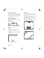
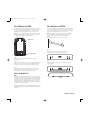
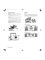
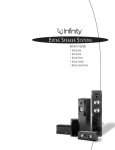
INFP2010Classia-OM
12/4/07
11:39 AM
Page 1
INFINITY CLASSIA SPEAKERS
™
OWNER’S GUIDE
C205
C336
CC225
INFP2010Classia-OM
12/4/07
11:39 AM
Page 2
INFINITY CLASSIA SERIES
HOME THEATER
The Infinity Classia™ series of loudspeakers continues the longstanding
Infinity® commitment to accurate sound reproduction. Our patented Ceramic
Metal Matrix Diaphragm (CMMD®) drivers, precision dividing networks
and rigid, well-braced enclosures combine to deliver uncompromised
performance in any stereo or multichannel home theater system.
In addition, Infinity Classia speakers are magnetically shielded for
safe placement adjacent to a television.
For front-channel use, place one speaker on the left and another on the
right, along either side of the television monitor. Since the speakers are
magnetically shielded, you can place them without worrying about the
field distorting the TV picture.
™
The CC225 center channel speaker should be placed on top of or directly
below the television and aimed toward the listening area.The CC225
speaker may also be wall-mounted. See page 3.
UNPACKING THE SPEAKERS
If you suspect damage from transit, report it immediately to your dealer.
Keep the shipping carton and packing materials for future use.
WHAT’S INCLUDED
CC225
For surround use, place speakers alongside the listening position.
Final placement depends on room acoustics, availability of space
and your listening preference (Figures 2 and 3).
NOTE: An Infinity powered subwoofer will add impact and realism to both
music and film soundtracks. Contact your Infinity dealer for recommendations on subwoofer models for your application.
Left
Front
Channel
C336
Spike Kit
1/4"-20 Screws
Center
Channel
Right
Front
Channel
Infinity
Subwoofer
(optional)
Cleats
Wall
Bracket
x4
Rubber Bumpers
(For Bottom of Speaker)
C205
x5
Rubber Bumpers (Four for Bottom
of Speaker, One for Rear of Speaker
if Wall-Mounting). See Page 3.
Couch
PLACEMENT
Left
Surround
Channel
Stereo
Before deciding where to place your speakers, survey your room and
think about placement, keeping the following points in mind, using
Figure 1 as a guide:
Right
Surround
Channel
Figure 2.This overhead view shows a typical
home theater plan.
• For best results, place the speakers 6'– 8' apart.
• Position each speaker so that the tweeter is approximately at ear level.
Infinity Subwoofer
(optional)
• Generally, bass output will increase as the speaker is moved closer to
a wall or corner.
Right
Front
Channel
Center
Channel
• Refer to the “Home Theater” section if you also plan to use the speakers
for home theater reproduction.
Right
Surround
Channel
Co
uc
h
Left
Front
Channel
Left
Channel
Right
Channel
Left
Surround
Channel
Figure 3.This figure shows an alternate layout,
which may be more suitable for some rooms.
Listening Position
Figure 1. Experiment with speaker placement to obtain the best
bass level and stereo imaging in your room.
2 INFINITY CLASSIA
INFP2010Classia-OM
12/4/07
11:39 AM
Page 3
WALL-MOUNTING THE C205
WALL-MOUNTING THE CC225
The C205 is designed to be mounted directly to a wall. Each speaker has
two keyholes on the back, and will require (2) 1-1/2," #8 wood screws
with a .33" (8.4mm) screwhead fastened to a wall stud. If a wall stud is
unavailable, install an anchor appropriate for a 1-1/2," #8 screw.
The CC225 is designed to be mounted directly to a wall.The bracket has
four holes on the back, and will require (4) 1-1/2," #8 wood screws with
a .33" (8.4mm) screwhead fastened to wall studs. If wall studs are unavailable, install anchors appropriate for a 1-1/2," #8 screw.
NOTE: The customer is responsible for the correct selection and use of
mounting hardware (available through hardware stores) that will ensure
the proper and safe wall-mounting of the speakers.
NOTE: The customer is responsible for the correct selection and use
of mounting hardware (available through hardware stores) that will
ensure the proper and safe wall-mounting of the speakers.
Step 1.
Attach the wall bracket to the wall at the desired location.
Keyhole mounts
Step 2.
Securely fasten the two cleats to the rear of the speaker,
using two included 1/4"-20 panhead screws per cleat.
Attach rubber bumper
Figure 4.
Step 1.
Mark the positions on the wall where you would like to place the
mounting screws.
Step 2.
Fasten two 1-1/2," #8 wood screws to the wall using the markings placed
in Step 1 as your guide. Leave an 11/16" space between the wall and
screwhead. If a wall stud is not available, use an appropriate anchor.
Step 3.
Carefully slide the cleats on the rear of the speakers over the tabs
of the wall bracket.
Step 3.
Place the speaker on the wall by aligning the keyholes on the back of
the speaker to the screwheads on the wall. Once positioned properly,
the speaker should slide down slightly and become secure.
INSTALLING SPIKED FEET
C336
Four metal spikes are supplied for use when using the outboard feet and
the speaker is to be placed on a carpeted surface to decouple the speaker
from the floor and prevent unwanted damping.To insert the spikes, gently
lay the speaker on its back (not its front or side) on a soft, nonabrasive
surface, unscrew the four rubber-tipped feet and store in a safe place.
Each spike then screws into the threaded insert. Make sure all four spikes
are screwed in completely for stability.
Top view
NEVER drag the speaker to move it, as this will damage the spikes, the feet, the
wood cabinet itself, and/or the floor. Always lift the speaker and carry it to its
new location.
INFINITY CLASSIA 3
INFP2010Classia-OM
12/4/07
11:39 AM
Page 4
WIRING THE SYSTEM
BI-WIRING
IMPORTANT: Make sure all equipment is turned off before making any
connections.
C336
For speaker connections, use a minimum #16-gauge speaker wire with
polarity coding.The side of the wire with a ridge or other coding is
usually considered positive polarity (i.e., +).
NOTE: If desired, consult your local Infinity dealer about speaker wire and
connection options.
The outer connection panel and internal dividing network of the C336 is
designed so that separate sets of speaker cables can be attached to the lowfrequency transducer and midrange/high-frequency transducer portions of this
dividing network.This is called bi-wiring. Bi-wiring can provide several sonic
advantages and considerably more flexibility in power amplifier selection.
The speakers have coded terminals that accept a variety of wire connectors.The most common connection is shown in Figure 5.
To ensure proper polarity, connect each + terminal on the back of the
amplifier or receiver to the respective + (red) terminal on each speaker,
as shown in Figure 6. Connect the – (black) terminals in a similar way.
See the owner’s guides that were included with your amplifier, receiver
and television to confirm connection procedures.
IMPORTANT: Do not reverse polarities (i.e., + to –, or – to +) when
making connections. Doing so will cause poor imaging and diminished
bass response.
Figure 7.
Single-Stereo Amplifier
Figure 5.This example shows how to connect bare wires to the terminals.
Figure 8.
Dual-Stereo Amplifier
Figure 9.
Figure 6. Wiring diagram shows polarity connections for one
channel of a stereo or home theater system.
4 INFINITY CLASSIA
INFP2010Classia-OM
12/4/07
11:39 AM
Page 5
FINAL ADJUSTMENTS
Check the speakers for playback, first by setting the system volume control
to a minimum level, and then by applying power to your audio system. Play
a favorite music or video segment and increase the system volume control
to a comfortable level.
NOTE: You should hear balanced audio reproduction across the entire
frequency spectrum. If not, check all wiring connections or consult
the authorized Infinity dealer from whom you purchased the system
for more help.
The amount of bass you hear and the stereo-image quality will be affected
by a number of different factors, including the room’s size and shape,
the construction materials used to build the room, the listener’s position
relative to the speakers, and the position of the speakers in the room.
Listen to a variety of music selections and note the bass level. If there is
too much bass, move the speakers away from nearby walls. Conversely, if
you place the speakers closer to the walls, there will be more bass output.
Nearby reflecting surfaces can adversely affect stereo-imaging quality. If
this happens, try angling the speakers slightly inward toward the listening
position until the optimal effect is achieved.
CARE OF YOUR SPEAKER SYSTEM
Each Infinity Classia cabinet has a finish that does not require any routine
maintenance. When needed, use a soft cloth to remove any fingerprints or
dust. Clean the grille by gentle vacuuming.
NOTE: Do not use any cleaning products or polishes on the cabinet
or grille.
In the event that your Infinity speaker needs service, contact your Infinity
dealer or distributor, or visit www.infinitysystems.com for the location of
the nearest service center.
INFINITY CLASSIA 5
INFP2010Classia-OM
12/4/07
11:39 AM
Page 6
SPECIFICATIONS
C205
C336
CC225
60Hz – 30kHz (–3dB)
55Hz – 40kHz (–6dB)
40Hz – 30kHz (–3dB)
35Hz – 40kHz (–6dB)
55Hz – 30kHz (–3dB)
50Hz – 40kHz (–6dB)
Recommended
Amplifier Power Range:
10 – 125 Watts
10 – 250 Watts
10 – 150 Watts
Sensitivity (2.83V @ 1 meter):
88dB
91dB
90dB
Nominal Impedance:
8 Ohms
8 Ohms
8 Ohms
Crossover Frequencies:
2.0kHz; 24dB/octave
500Hz, 2.8kHz; 24dB/octave
2.0kHz; 24dB/octave
Low-Frequency Driver(s):
5-1/4" (133mm) CMMD,®
magnetically shielded
Triple 6-1/2" (165mm) CMMD,®
magnetically shielded
Dual 5-1/4" (133mm) CMMD,®
magnetically shielded
Mid-Frequency Driver:
N/A
4" (100mm) CMMD,
magnetically shielded
N/A
High-Frequency Driver:
1" (25mm) CMMD,
magnetically shielded
1" (25mm) CMMD,
magnetically shielded
1" (25mm) CMMD,
magnetically shielded
Dimensions (H x W x D):
15-1/8" x 7-1/2" x 9-1/4"
(384mm x 190mm x 235mm)
48-3/4" x 8-1/2" x 10-1/2"
(1238mm x 216mm x 267mm)
6-7/8" x 31-3/4" x 5"
(175mm x 806mm x 127mm)
Weight:
10.8 lb (4.9kg)
56.1 lb (25.4kg)
16 lb (7.3kg)
Frequency Ranges:
Features, specifications and appearance are subject to change without notice.
Declaration of Conformity
We, Harman Consumer Group, Inc.
2, route de Tours
72500 Château du Loir
France
declare in own responsibility that the products described
in this owner’s manual are in compliance with technical
standards:
EN 61000-6-3:2001
EN 61000-6-1:2001
Laurent Rault
Harman Consumer Group, Inc.
Château du Loir, France 12/07
6 INFINITY CLASSIA
INFP2010Classia-OM
12/4/07
11:39 AM
Page 7
NOTES
INFINITY CLASSIA 7
INFP2010Classia-OM
12/4/07
11:39 AM
Page 8
© 2007 Harman International Industries, Incorporated. All rights reserved.
Infinity Systems, 250 Crossways Park Drive, Woodbury, NY 11797 USA 516.674.4463 (USA only) www.infinitysystems.com
Infinity and CMMD (patent nos. 6,327,372 and 6,404,897) are trademarks of Harman International Industries, Incorporated,
registered in the United States and/or other countries. Infinity Classia is a trademark of Harman International Industries, Incorporated.
Part No. BO-13333-01 12/07